manuals.online logo
Brands
  1. Home
  2. •
  3. Brands
  4. •
  5. ORiNG
  6. •
  7. Network Router
  8. •
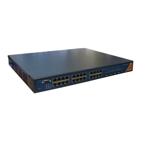
  9. ORiNG RGS-9244GP User manual

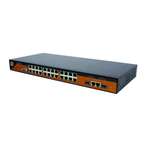
ORiNG RGS-9244GP User manual

G2 G4 G6 G8
G1 G3 G5 G7
LINK /ACT
Cons ole
G25 G26 G27 G 28
RGS-R9244GP+
R.M.
Ring
Reset
10/100/
1000T
Fault
10G SF P+
G10 G12 G14 G16
G9 G11 G13 G15
G18 G20 G22
G17 G19 G21 G23
G24
PWR
G2 G4 G6 G8
G1 G3 G5 G7
LINK/A CT
Consol e
G25 G26 G 27 G28
RGS-9244GP
R.M.
Ring
Reset
10/100/
1000T
Fault
100/1000X
G10 G12 G14 G16
G9 G11 G13 G15
G18 G20 G22
G17 G19 G21 G23
G24
PWR
Quick Installation Guide
Version 1.2
Quick Installation Guide
Introduction
PRINTED ON RECYCLED PAPER
Q I G RGS-9244GP Series 1907-2-29-RGS9244GP-1.2
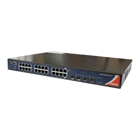
The which consist of , andRGS-9244GP series RGS-9244GP RGS-9244GP-
E, are rack-mount Ethernet switches with twenty-four 10/100/1000BaseT(X)
Ethernet ports and four 100/1000Base-X SFP ports. The isRGS-9244GP-E
an enhanced model with dual DC inputs and relay output. With complete
support for Ethernet redundancy protocols such as O-Ring (recovery time <
30ms over 250 units of connection), O-Chain, MRP , Fast Recovery,*NOTE
and MSTP (RSTP/STP compatible), the switch can protect your mission-
critical applications from network interruptions or temporary malfunctions
with its fast recovery technology. Featuring a wide operating temperature
from -40 C to 75 C, the device can be managed centrally and conveniently
o o
via Open-Vi s i o n u t i l ity, web browsers, Te l net and console (CLI)
configuration, making it to be one of the most reliable choice for highly-
managed and Fiber Ethernet application.
Preparation
Before you begin installing the switch, make sure you have all of the package
contents available and a PC with Microsoft Internet Explorer 6.0 or later, for
using web-based system management tools.
Elevated Operating Ambient: If installed in a closed or multi-unit rack
assembly, the operating ambient temperature of the rack environment may be
greater than room ambient. Therefore, consideration should be given to
installing the equipment in an environment compatible with the maximum
ambient temperature (Tma) specified by the manufacturer.
Safety & Warnings
Dimension
Panel Layouts
1. Console port
2. Reset button
3. Power indicator
4. Ring status LED
5. RM status LED
6. Fault indicator
Front View
Rear View
Package Contents
Contents
QIG
CD
Console Cable
Screw (M4 X6)
Power cord
Rack-mounted
kit (L&R)
Number
X 1
X 1
X 1
X 6
X 1
X 1
RGS-9244GP or
RGS-9244GP-E
Pictures
X 1
35. 0
44.00
8.0 0 20.00
25.00
32. 0
4.0
Ø6. 5
25.40
342 .0 0
3.0
44.50
431 .0 0
1
2 3 4 5 6 7
8 9
10 11
7. LAN ports
8. LED for Ethernet ports LNK/ACT status
9. LED for Ethernet ports speed indicator
10. SFP ports
11. LNK/ACT LED for SFP ports
1 2
1. Power switch
2. AC power input (100V~240V
/ 50~60Hz)
3. Dual DC power inputs
(RGS-9244GP-E Only)
M A N A G E D
Rack-Mount
G I G A B I T
S W I T C H
Reduced Air Flow: Installation of the equipment in a rack should be such that the
amount of air flow required for safe operation of the equipment is not
compromised.
Mechanical Loading: Mounting of the equipment in the rack should be such that a
hazardous condition is not achieved due to uneven mechanical loading.
Circuit Overloading: Consideration should be given to the connection of the equipment
to the supply circuit and the effect that overloading of the circuits might have on
overcurrent protection and supply wiring. Appropriate consideration of equipment
nameplate ratings should be used when addressing this concern.
Network Connection
The series have standard Ethernet ports. According to the link type, the switch uses CAT 3, 4,
5,5e UTP cables to connect to any other network devices (PCs, servers, switches, routers, or
hubs). Please refer to the following table for cable specifications.
Cable Types and Specifications:
Cable Type Max. Length Connector
10BASE-T Cat. 3, 4, 5 100-ohm UTP 100 m (328 ft) RJ-45
100BASE-TX Cat. 5 100-ohm UTP UTP 100 m (328 ft) RJ-45
1000BASE-T Cat. 5 / Cat. 5e 100-ohm UTP UTP 100 m (328 ft) RJ-45
Installation
Rack-mounting
Step 1: Install left and right front mounting brackets to the switch using three screws on each side.
Step 2: With front brackets orientated in front of the rack, fasten the brackets to the rack using two
more screws.
For pin assignments for different types of cables, please refer to the following tables.
1000Base-T RJ-45
Pin Number Assignment
1 BI_DA+
2 BI_DA-
3 BI_DB+
4 BI_DC+
5 BI_DC-
6 BI_DB-
7 BI_DD+
8 BI_DD-
10/100Base-T(X) RJ-45
Pin Number Assignment
1 TD+
2 TD-
3 RD+
4 Not used
5 Not used
6 RD-
7 Not used
8 Not used
RGS-9244GP Series
49. 0
AC 100-240V 50-60Hz
PW3
V+ V-
PW2 1A@24V
DC Power 36V~72V
AC 100-240V 50-60Hz
PW3
V+ V-
PW2 1A@24V
DC Power 36V~ 72V
3
Managed Gigabit Ethernet Switch
G2 G4 G6 G8
G1 G3 G5 G7
LINK/A CT
Consol e
G25 G26 G 27 G28
RGS-9244GP-E
Reset
10/100/
1000T
100/1000X
G10 G12 G14 G16
G9 G11 G13 G15
G18 G20 G22
G17 G19 G21 G23
G24
RingP1
Fault
R.M.
P2
P3
G2 G4 G6 G8
G1 G3 G5 G7
LINK /ACT
Cons ole
G25 G26 G27 G 28
RGS-9244GP-E
Reset
10/1 00/
1000 T
100/1000X
G10 G12 G14 G16
G9 G11 G13 G15
G18 G20 G22
G17 G19 G21 G23
G24
RingP1
Fault
R.M.
P2
P3
1
2 3 4 5 6 7
8 9
10 11
*NOTE: This function is available by request only
Unit =mm (Tolerance ±0.5mm)
Q I G Quick Installation Guide
PRINTED ON RECYCLED PAPER
Version 1.2
Quick Installation Guide
M A N A G E D
Rack-Mount
G I G A B I T
S W I T C H
1. Launch the Internet Explorer and type in IP address of the switch. The default static IP address is
192.168.10.1
2. Log in with default user name and password (both are ). After logging in, you should seeadmin
the following screen. For more information on configurations, please refer to the user manual.
For information on operating the switch using ORing’s Open-Vision management utility, please go to
ORing website.
Resetting
To reboot the switch, press the button for 5 seconds.Reset
To restore the switch configurations back to the factory defaults, press the button for 10 seconds.Reset
Specifications
ORin g S w i t c h M odel
Phys i c a l P o r ts
Tech n o l o g y
Et h ernet Sta n dards
10 / 100/100 0 Base-T(X ) w ith
RJ 4 5 Auto MDI / M DIX
RS - 232 Seria l C onsole Port
Sw itch Prop e rties
Se c urity Features
De v ice Bindi n g securit y f eature
En a ble/dis a ble ports , M AC based po r t securit y
Port based n e twork acc e ss contro l ( 802.1x)
MA C-base d a uthenti c ation
Gu e st VLAN
VL A N (802.1Q ) t o segrega t e an secure n e twork traffic
Radius cen t raliz e d passwor d m anageme n t
SN M Pv3 encry p ted authe n ticatio n a nd access s e curity
Ht t ps / SSH enh a nce netwo r k securit y
Web and C L I authent i cation an d a uthoriz a tion
IP s o urce guar d
So f tware Features
IE E E 802.1D Br i dge, auto M A C address l e arning/ a ging and MA C a ddress (s t atic)
Mu l tiple Re gistra tion Prot o col (MRP)
MS T P (RSTP/S T P c ompati b le)
TOS/Diff s erv suppo r ted
Qu a lity of Se r v ice (802 . 1 p) for rea l -time tra ffic
VL A N (802.1Q ) w ith VLAN ta g ging
IG M P v2/v3 Sno o ping
Ap p licatio n -based Qo S m anageme n t
DO S /DDOS aut o p revent i on
Port confi g urati o n, status , s tatisti c s, monito r ing, secu r ity
DH C P Server / Client/ Relay
Mo d bus TCP
SM T P Client
NT P s erver
Ne t work Re d undancy O- R ing, O-Ch a in, MRP , MS T P (RST/ST P c ompatib l e), Fast Rec overy*N O TE
RS - 232 in DB-9 c o n nector w i t h consol e c a ble. 115200b p s, 8, N , 1
RGS- 9 2 4 4 G P
24
IE E E 802.3ab f o r 1000Bas e -T
IE E E 802.3x fo r F low contr o l
IE E E 802.3ad f o r LACP (Lin k A ggregat i on Contro l P rotocol )
IE E E 802.1p fo r C OS (Class o f S ervice)
IE E E 802.1Q fo r V LAN Tag ging
IE E E 802.1w fo r R STP (Ra p id Spanni n g Tree Pr o t ocol)
IE E E 802.1s fo r M STP (Mult i ple Spann i ng Tree P r otocol)
IE E E 802.1x fo r A uthent i c ation
IE E E 802.1AB f o r LLDP (Lin k L ayer Di s cover y P r otocol )
Sw itch late n cy: 7 us
Sw itch band w idth: 56G b ps
Ma x . Number of Avai l a ble VLAN s : 4 095
VL A N ID Rang e : VID 0 to 4095
IG M P multica s t groups: 2 5 6 for each VL A N
Port rat e l imiting : U ser Defin e
MA C Tabl e 8K
Pr o cessing S t ore-an d - Forw ard
Pr i ority Que u es 8
Ju m bo fram e Up t o 1 0K Bytes
Powe r
Power cons u mption( Typ.) 30 Watt s m ax.
Ov e rload cu r rent prot e ction NOT Presen t
Power inpu t 10 0 ~240VAC (88~26 4 VAC/ 1 2 5~373VD C ) with powe r
so c ket
10 0 /1000Ba s e-X w i th SFP port 4
Envir o n m e n tal
-4 0 t o 85 C ( - 4 0 to 185 F)
o o
St o rage Tempera ture
Op e ratin g Temperature
Phys i c a l C h a racteristic
Di m ension (W x D x H )
Weigh t ( g) 4210g
5% t o 9 5% Non-co n densing
Op e ratin g H u midity
En c losure 19 i n ches ra c k mountab l e, IP-20
43 1 ( W) x 342 (D) x 44 ( H ) mm (16.97 x 1 3 .47 x 1.73 i n ch.)
-4 0 t o 75 C ( - 4 0 to 167 F)
o o
Regul a t o r y A pprovals
EN 5 5 032, CISP R 32 EN 61000 - 3-2, EN 610 0 0-3-3, FC C Part 15 B c l ass AEM I
EN 5 5 024 (IEC/ E N 61000-4 - 2 (ESD), EN 6 1 000-4-3 ( R S), EN 6100 0 -4-4 (EFT), E N 6 1000-4- 5 ( Surge) ,
EN 6 1 000-4-6 ( C S), EN 6100 0 -4-8 (PFM F ), EN 61000 - 4-11 (DIP ) )
EM S
Warr a n t y
5 ye ars
MTBF
39 5 ,736 hrs
IE C 60068-2 - 27Sh o ck
IE C 60068-2 - 31Fr e e Fa l l
IE C 60068-2 - 6Vi b ratio n
Fault C o n t a c t
Relay Non e
Wiring
10/100Base-T(X) MDI/MDI-X
Pin Number MDI port MDI-X port
1 TD+(transmit) RD+(receive)
2 TD-(transmit) RD-(receive)
3 RD+(receive) TD+(transmit)
4 Not used Not used
5 Not used Not used
6 RD-(receive) TD-(transmit)
7 Not used Not used
8 Not used Not used
1000Base-T MDI/MDI-X
Pin Number MDI port MDI-X port
1 BI_DA+ BI_DB+
2 BI_DA- BI_DB-
3 BI_DB+ BI_DA+
4 BI_DC+ BI_DD+
5 BI_DC- BI_DD-
6 BI_DB- BI_DA-
7 BI_DD+ BI_DC+
8 BI_DD- BI_DC-
Note: “+” and “-” signs represent the polarity of the wires that make up
each wire pair.
To connect the console port to an external management device, you need an DB-9
cable, which is also supplied in the package. Below is the console port pin assignment
information.
Console Port Pin Definition
PC RS-232 to DB9 (male) pin
assignment
RS-232 with DB9 (female) pin
assignment
PIN#2 RxD PIN#2 RxD
PIN#3 TxD PIN#3 TxD
PIN#5 GND PIN#5 GND
AC Power Connection
Both RGS-9244GP and RGS-9244GP-E can be powered by AC electricity. Simply
insert the AC power cable to the power connector at the back of the switch and
turn on the power switch. The input voltage is 100V~240V / 50~60Hz.
DC Power Connection
The RGS-9244GP-E supports dual DC power supplies,
Power Supply 2 (PWR2) and Power Supply 3 (PWR3). The
connections for PWR1, PWR2 and the RELAY are located on
the terminal block. The input voltage is 24V~72VDC.
STEP 1: Insert the negative/positive wires into the V-/V+ terminals, respectively.
STEP 2: To keep the DC wires from pulling loose, use a small flat-blade
screwdriver to tighten the wire-clamp screws on the front of the terminal block
connector.
Relay contact
The RGS-9244GP-E provides two sets of relay contacts on the 6-pin terminal block to
detect user-configured events. The two wires attached to the fault contacts form an
open circuit when a user-configured when an event is triggered. If a user-configured
event does not occur, the fault circuit remains closed.
Grounding
Grounding and wire routing to help limit the effects of noise due to electromagnetic
interference (EMI). Run the ground connection from the ground screws to the grounding
surface prior to connecting devices.
V+ V- V- V+
1A@24V
DC Power 36~ 72V
PW2 PW3
IE E E 802.3 for 1 0 Base-T
IE E E 802.3u fo r 1 00Base-T X
IE E E 802.3z fo r 1 000Base -X
Configurations
After installing the switch and connecting cables, start the switch by turning on power.
The green power LED should turn on.
LED indication table
LED
Color
Status
Description
PWR Green On System power is connected
R.M Green On Device is operating as a ring master
Ring Green On Ring is enabled and device is running in Ring mode
Blinking Ring structure is broken
Fault Amber On Errors (power failure or port malfunctioning)
10/100/1000Base-T(X) RJ45 port
LNK/ACT Green On Port is connected
Blinking Transmitting data
Speed
Green On Port is running at 1000Mbps
Amber On Port is running at 100Mbps
Off Port is running at 10Mbps
100/1000X SFP port
LNK/ACT Green On Port is connected
Blinking Transmitting data
RGS- 9 2 4 4 G P -E
10 0 ~240VAC (88~26 4 VAC/ 1 2 5~373VD C )with pow e r
so c ket, dua l 4 8VDC (24~ 7 2VDC) at 6- p in termin a l block
30 w atts max. f o r DC power in p ut
30 . 6 watts ma x . for AC powe r i nput
4652g
Relay out p ut to carry c a pacity o f 1 A at 24VDC
RGS-9244GP Series
RGS-9244GP Series Managed Gigabit Ethernet Switch
Pr e sent with t e rminal bl o ck
CE E M C (EN 55024 , E N 55032), F C C Part 1 5 BEM C
EN 6 0950-1Sa f ety
ORing Industrial Networking Corp.
Copyright© 2016 ORing
All rights reserved.
TEL: +886-2-2218-1066
FAX: +886-2-2218-1014
Website: www.oringnet.com
E-mail: support@oringnet.com
Warr a n t y
5 ye ars
Warr a n t y
5 ye ars
34 4 ,230 hrs
*NOTE: This function is availab le by req uest on ly

Other manuals for RGS-9244GP

1

This manual suits for next models

2

Other ORiNG Network Router manuals

ORiNG CPGS-9080-C User manual

ORiNG

ORiNG CPGS-9080-C User manual

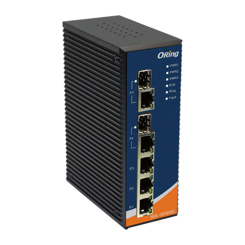
ORiNG IGS-3032GC User manual

ORiNG

ORiNG IGS-3032GC User manual

ORiNG IR-711UB User manual

ORiNG

ORiNG IR-711UB User manual

ORiNG RES-P3242GCL SERIES User manual

ORiNG

ORiNG RES-P3242GCL SERIES User manual

ORiNG TGXPS-1080-M12-MV Series User manual

ORiNG

ORiNG TGXPS-1080-M12-MV Series User manual

ORiNG TES-3082GT-M12-BP1 User manual

ORiNG

ORiNG TES-3082GT-M12-BP1 User manual

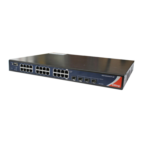
ORiNG RGS-92222GCP-NP Series User manual

ORiNG

ORiNG RGS-92222GCP-NP Series User manual

ORiNG RGPS-9084GP-P User manual

ORiNG

ORiNG RGPS-9084GP-P User manual

ORiNG TGAR-1062-M12-3G User manual

ORiNG

ORiNG TGAR-1062-M12-3G User manual

ORiNG RES-9242GC User manual

ORiNG

ORiNG RES-9242GC User manual

ORiNG IGS-9122GPM User manual

ORiNG

ORiNG IGS-9122GPM User manual

ORiNG TGPS-9084GT-M12 User manual

ORiNG

ORiNG TGPS-9084GT-M12 User manual

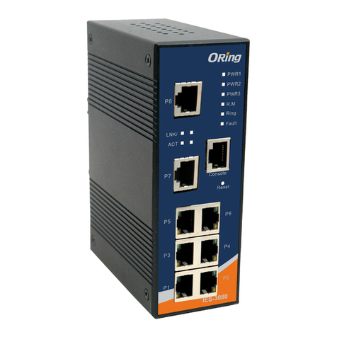
ORiNG IES-3080 Series User manual

ORiNG

ORiNG IES-3080 Series User manual

ORiNG IES-3242GC User manual

ORiNG

ORiNG IES-3242GC User manual

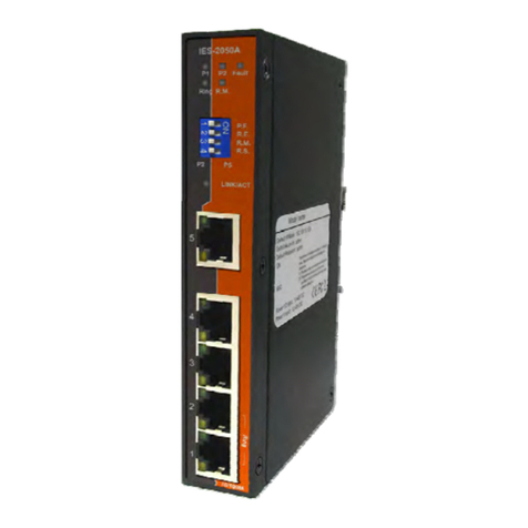
ORiNG IES-2050A User manual

ORiNG

ORiNG IES-2050A User manual

ORiNG IES-3082GC User manual

ORiNG

ORiNG IES-3082GC User manual

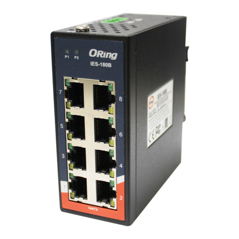
ORiNG IES-180B User manual

ORiNG

ORiNG IES-180B User manual

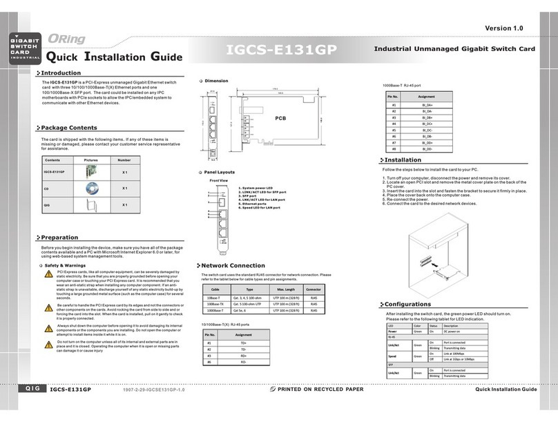
ORiNG IGCS-E131GP User manual

ORiNG

ORiNG IGCS-E131GP User manual

ORiNG IGS-P9164 Series User manual

ORiNG

ORiNG IGS-P9164 Series User manual

ORiNG TGPS-9164GT-M12X-BP2-MV User manual

ORiNG

ORiNG TGPS-9164GT-M12X-BP2-MV User manual

ORiNG IR-710 User manual

ORiNG

ORiNG IR-710 User manual

ORiNG TES-3082GT-M12-BP1 User manual

ORiNG

ORiNG TES-3082GT-M12-BP1 User manual

ORiNG IAR-630-D User manual

ORiNG

ORiNG IAR-630-D User manual

ORiNG IES-2042PA User manual

ORiNG

ORiNG IES-2042PA User manual

Popular Network Router manuals by other brands

Show Tec 50809 manual

Show Tec

Show Tec 50809 manual

Westermo MRD-350 user guide

Westermo

Westermo MRD-350 user guide

RuggedCom RuggedSwitch RSG2100P installation guide

RuggedCom

RuggedCom RuggedSwitch RSG2100P installation guide

Magnum Dimensions ACLD-40 owner's manual

Magnum Dimensions

Magnum Dimensions ACLD-40 owner's manual

Planet ADE-3400 user manual

Planet

Planet ADE-3400 user manual

Ravpower RP-WD009 user guide

Ravpower

Ravpower RP-WD009 user guide

Telindus 1120 user guide

Telindus

Telindus 1120 user guide

Dynex DX-GB8PRT Quick setup guide

Dynex

Dynex DX-GB8PRT Quick setup guide

Juniper PTX3000 quick start

Juniper

Juniper PTX3000 quick start

Asus RT-AC56S user guide

Asus

Asus RT-AC56S user guide

D-Link G413K user manual

D-Link

D-Link G413K user manual

ZyXEL Communications IES-2500 user guide

ZyXEL Communications

ZyXEL Communications IES-2500 user guide

Asus DSL-AC52U quick start guide

Asus

Asus DSL-AC52U quick start guide

Sitecom WL-607 manual

Sitecom

Sitecom WL-607 manual

MikroTik RouterBOARD Metal 5SHPN Quick setup guide and warranty information

MikroTik

MikroTik RouterBOARD Metal 5SHPN Quick setup guide and warranty information

Robustel GoRugged R2000 Installation and configuration guide

Robustel

Robustel GoRugged R2000 Installation and configuration guide

NETGEAR DG834v2 - ADSL Modem Router Specifications

NETGEAR

NETGEAR DG834v2 - ADSL Modem Router Specifications

TP-Link Archer C2 Quick installation guide

TP-Link

TP-Link Archer C2 Quick installation guide

manuals.online logo
manuals.online logoBrands
  • About & Mission
  • Contact us
  • Privacy Policy
  • Terms and Conditions

Copyright 2025 Manuals.Online. All Rights Reserved.