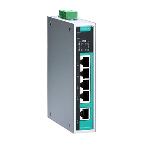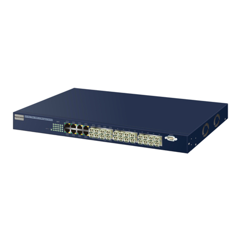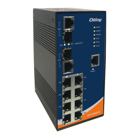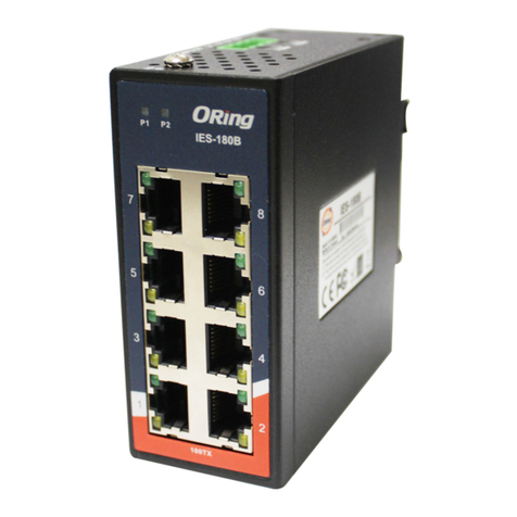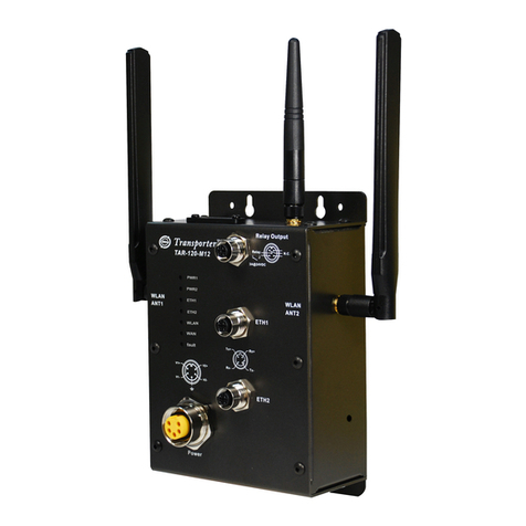
Q I G Quick Installation Guide
Quick Installation Guide
Version 2.1
Q I G
Resetting
To reboot the switch, press the button for 2-3 seconds.Reset
To restore the switch configurations back to the factory defaults, press the button for 5 seconds.Reset
Wiring
The switch provides three DC inputs. The 12~48VDC
power supply is on 7-pin terminal block, along with
the grounding screw and relay output, and the
12~45VDC is on a power jack. Follow the steps
below to wire power cables on the terminal block.
Power inputs
The relay contact on the terminal block allow you to form fail close circuits. The
relay contact will respond to user-configured events according to the setting.
Relay contact
Grounding and wire routing help limit the effects of noise due to electromagnetic
interference (EMI). Run the ground connection from the ground screws to the grounding
surface prior to connecting devices.
Grounding
1. Launch the Internet Explorer and type in IP address of the switch. The default static IP address is
192.168.10.1
2. Log in with default user name and password
(both are ). After logging in, you shouldadmin
see the following screen. For more information
on configurations, please refer to the user
manual. For information on operating the switch
using ORing’s Open-Vision management utility,
please go to ORing website.
Follow the steps to set up the card:
Specifications
STEP 1: Insert the negative/positive wires into the V-/V+ terminals, respectively.
STEP 2: To keep the wires from pulling loose, use a small flat-blade screwdriver to
tighten the wire-clamp screws on the front of the connector.
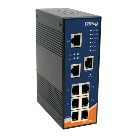
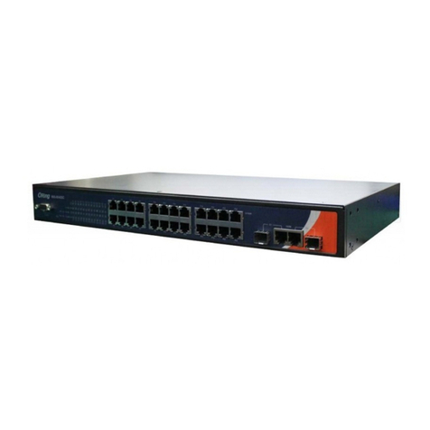
ORing Switch Model IES-3080
10 /1 00 B ase-T(X) Por ts i n
RJ 45 A uto MDI/MDIX 8
Physical Ports
6
IE EE 8 02 .1p for COS (Class of S er vi ce)
IE EE 8 02 .1Q for VLAN Tagging
IE EE 8 02 .1w for RSTP (Rap id S panning Tree Protoc ol )
IE EE 8 02 .1AB for MSTP (Mult ip le S panning Tree Protoc ol )
IE EE 8 02 .1x for Authentic at ion
IE EE 8 02 .1AB for LLDP (Link L ayer Discover y Pr otocol)
Fault Contact
Relay Rel ay output to carry capa ci ty of 1A at 24 VDC
Power
Redundant Input pow er
Power consumption (Typ.)
Triple DC inputs. 12 ~4 8V DC on 7-pin termina l bl oc k, 12~45VDC on powe r ja ck
5 Watts
Ov er load current prot ec ti on
Reverse polar it y protection
Pr es en t
Pr es en t on terminal block
Physical Characteri st ic
En cl os ure IP-30 Aluminu m
Di me ns ion (W x D x H) 52 (W )x 107.1(D)x144.3( H) m m (2.05x4.21x5.68 i nc h. )
Weight (g )
Environmental
-4 0 to 8 5 C ( -4 0 to 1 85 F )
o o
St orage Tempera ture
IES-3062FX-SS
MA C Table 8K
Packet buffer 1M bi ts
Pr oc es sing Store-an d- Forward
Sw it ch Properties
Sw it ching latency: 2. 03 sµ
Sw it ching bandwidth :
IE S- 30 80/IES-3062FX Ser ie s: 1.6Gbps
IE S- 30 62GT/IES-3062GF S er ies: 5.6Gbps
Th ro ug hput (packet pe r se co nd):
IE S- 30 80/IES-3062FX Ser ie s: 76.19Mpps@64By te s pa cket
IE S- 30 62GT/IES-3062GF S er ies: 761.91 Mpps@64 By te s packet
Ma x. N um ber of Avai lable VLANs: 4096
VL AN I D Range: VID 1 to 409 5
IG MP m ul ticast groups: 10 24
Port rate lim it in g: User Define
Se cu ri ty Featur es
En ab le /disable ports, M AC b as ed port security
Port based network ac ce ss control (802.1x)
VL AN ( 80 2.1Q) to segregat e an d se cure network traf fic
Su pp or ts Q-in-Q VLAN for pe rf or mance & security to e xp an d the VLAN space
Radius centra li zed password manage me nt
SN MP V 1/ V2c/V3 encrypte d au th entication and acce ss s ecurity
So ft ware Feat ur es
ST P/ RS TP/MSTP (IEEE 802.1 D/ w/ s)
Redundant Ring (O-R in g) with recover y ti me l ess than 10/30ms ov er 250 units
Fast Ethern et p orts supports less 10 m il liseconds recov er y time.NO TE 1 .
Gi ga bi t Ethernet ports su pp or ts less 30 millisec on ds r ecovery timeNO TE 2 .
TOS/Diffserv su pp or ted
Qu al ity of Service (802.1 p) f or real-time traf fic
VL AN ( 80 2.1Q) with VLAN tag gi ng a nd GVRP supported
IG MP S no oping for multica st f il tering
Port configurat ion, status, statis ti cs , monitoring, sec ur ity
SN TP f or s ynchronizing of c lo ck s over network
Su pp or t PTP Client (Preci si on T ime Protocol) clock s yn chronization
DH CP S er ver / Client supp or t
Port Trunk s up po rt
MV R (M ul ticast VLAN Reg istration) su pp or t
Mo db us TCP
Ne tw or k Redundanc y O- Ri ng , O-Chain, MRP , S TP / R STP / MSTP*N OT E
-4 0 to 7 5 C ( -4 0 to 1 67 F )
o o
Op erating Tempe rature
5% t o 95 % No n-condensingOp erating Humidit y
Regulatory Approval s
CE E MC ( EN 5 5024, EN 55032), FC C Part 15 BEM C
Fi be r Ports Numbe r -
Fi be r Port Specificatio n
Fi be r Di am eter (µm) 62 .5 /1 25 µ m
50 /1 25 µ m
Fi be r Op ti cal Connector SC
Typical Distance (Km) 2 Km
-
-
-
2
9/ 12 5 µm
SC
30 K m
Fi be r Ports Standard 100Base-FX
Fi be r Mo de Mu lt i- mo de
-
-
10 0B as e- FX
Si ng le -m ode
EN 5 50 24 ( IEC/EN 61000-4- 2 (E SD : Contact 4KV, Air 8KV), IEC/EN 61 00 0- 4-3 (RS: 3V),
IE C/ EN 6 1000-4-4 (EFT Pow er 0 .5KV, Signal 0.5KV) , IE C/ EN 61000-4-5 (Surge : Power 0.5KV, RJ45 1KV),
IE C/ EN 6 1000-4-6 (CS: 3V), IE C/ EN 61000-4-8(PFMF ), I EC /EN 61000-4-11 (DIP ))
EM S
IE C6 00 68-2-27Sh oc k
IE C6 00 68-2-31
IE C6 00 68-2-6Vi bration
EN 60 95 0-1(LVD)
Sa fe ty
Fr ee Fall
MTBF
84 1, 59 9 hrs
PRINTED ON RECYCLED PAPER
PWR-3 12 -45 VDC
-
+
To connect the console port to an external management device, you need an RJ-45 to DB-
9 cable, which is also supplied in the package. Below is the console port pin assignment
information.
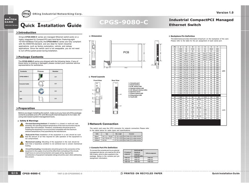
Console Port Pin Definition
PC (male) pin assignment RS-232 with DB9 (female) pin
assignment (RJ45-DB9 cable) RJ45 pin assignment
PIN#2 RxD PIN#2 RxD PIN#2 RxD
PIN#3 TxD PIN#3 TxD PIN#3 TxD
PIN#5 GND PIN#5 GND PIN#5 GND
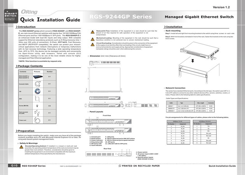
For pin assignments for different types of cables, please refer to the following
tables.
10/100 Base-T(X) MDI/MDI-X
Pin Number MDI port MDI-X port
1 TD+(transmit) RD+(receive)
2 TD-(transmit) RD-(receive)
3 RD+(receive) TD+(transmit)
4 Not used Not used
5 Not used Not used
6 RD-(receive) TD-(transmit)
7 Not used Not used
8 Not used Not used
Note: “+” and “-” signs represent the polarity of the wires that make up each wire pair.
1000Base-T MDI/MDI-X
Pin Number MDI port MDI-X port
1 BI_DA+ BI_DB+
2 BI_DA- BI_DB-
3 BI_DB+ BI_DA+
4 BI_DC+ BI_DD+
5 BI_DC- BI_DD-
6 BI_DB- BI_DA-
7 BI_DD+ BI_DC+
8 BI_DD- BI_DC-
1000Base-T RJ-45 Port
Pin Number Assignment
1 BI_DA+
2 BI_DA-
3 BI_DB+
4 BI_DC+
5 BI_DC-
6 BI_DB-
7 BI_DD+
8 BI_DD-
10/100 Base-T(X) RJ-45 Port
Pin Number Assignments
1 TD+
2 TD-
3 RD+
4 Not used
5 Not used
6 RD-
7 Not used
8 Not used
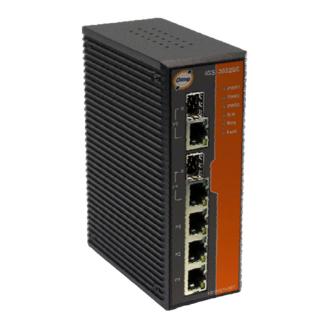
IES-3062GT IES-3062 FX -MM IES-3062GF-SSIES-3062GF-MM
10 /1 00 /1000 Base-T(X) Ports
in R J4 5 Auto MDI/MDIX -
-
-
-
-
-
-
6
2-
6
2
-
6
62 .5 /1 25 µ m
50 /1 25 µ m
SC
0. 55 K m
2
9/ 12 5 µm
SC
10 K m
10 00 Ba se -SX
Mu lt i- mo de
10 00 Ba se -LX
Si ng le -m ode
-
6
2
-
Technology
Et he rn et Standards
IE EE 8 02 .3 for 10Base-T
IE EE 8 02 .3u for 100Base-TX a nd 1 00 Base-FX
IE EE 8 02 .3z for 1000Base-X
IE EE 8 02 .3ab for 1000Base -T
IE EE 8 02 .3ad for LACP (Link A gg re gation Control Prot oc ol )
IE EE 8 02 .3x for Flow contro l
IE EE 8 02 .1D for STP (Spanni ng Tree Protocol )
RS -2 32 S erial Console Port RS -2 32 i n RJ45 connector wi th c on sole cable. Ba ud rate setting: 96 00 bp s, 8, N, 1
8 Watts 7 Watts7 Watts9 Watts9 Watts
71 0 g 722 g 74 0 g74 0 g73 5 g73 5 g
EN 5 50 32 , CISPR32, EN 61000 -3 -2 , EN 61000-3-3, VCCI cl as s A, C-Tick clas s A, F CC Part 15 B clas s AEM I
Warranty
5 ye ar s
79 8, 35 0 hrs 55 0, 16 5 hrs 47 9, 54 2 hrs 43 2, 00 0 hrs 50 3, 31 8 hrs
*NOTE : This function is available by request only
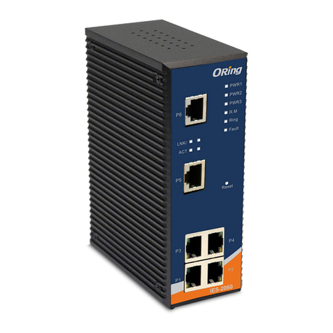
IES-3080/3062 Series
IES-3080/3062 Series
S w i tc h
R e d u n da n t
I N D U S T R I A L
Industrial Managed Ethernet Switch
Pr io ri ty Queues 4
ORing Industrial Networking Corp.
Copyright© 2011ORing
All rights reserved.
TEL: +886-2-2218-1066
FAX: +886-2-2218-1014
Website: www.oringnet.com
E-mail: support@oringnet.com
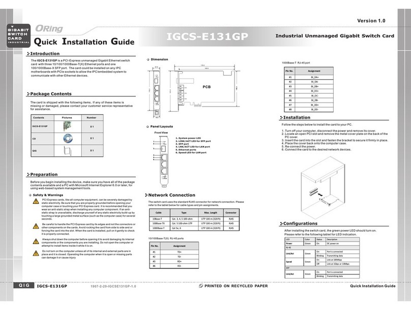
Configurations
After installing the switch, the green power LED should turn on. Please refer to the
following tablet for LED indication.
PW1 Green On Power module 1 activated
PW2 Green On Power module 2 activated
PW3 Green On Power module 3 activated
R.M Green On System running in Ring Master mode
Ring Green
On System running in Ring mode
Blinking Ring structure is broken (i.e. part of the ring is
disconnected)
Fault Amber On Faulty relay (power failure or port malfunctioning)
10/100Base-T(X) Fast Ethernet ports
LNK/ACT Green
On Links are connected
Off Links are dis-connected
Blinking Transmitting data
Duplex/
Collision Amber
On Full-duplex
Off Half-duplex
Blinking Half-duplex and collision occurred
10/100/1000Base-T(X) Ports
LNK/ACT Green
On Links are connected
Off Links are dis-connected
Blinking Transmitting data
Speed Amber On Port link at 100Mbps
Off Port link at 10/1000Mbps
Fiber ports
LNK/ACT Green
On Links are connected
Off Links are dis-connected
Blinking Transmitting data
LNK Amber On Links are connected
Off Links are dis-connected
Wavel en gt h (n m) 13 10 n m
Ma x. O ut pu t Optical Power
(d bm ) -1 4 db m
Mi n. O ut pu t Optical Power
(d bm ) -2 3. 5 dbm
Ma x. I np ut O ptical Power
Sa tu ration( ) 0 db m
Mi n. I np ut O ptical Power
Se ns it iv ity( ) -3 1 db m
Li nk B ud ge t (db) 7. 5 db
-
-
-
-
-
-
13 10 n m
-8 d bm
-1 5 db m
0 db m
-3 4 db m
19 d b
-
-
-
-
-
-
85 0 nm
-4 d bm
-9 .5 d bm
0 db m
-1 8 db m
8. 5 db
13 10 n m
-3 d bm
-9 .5 d bm
-3 d bm
-2 0 db m
10 .5 d b


