Orion OLMU-K4953 User manual

Infinitely Expandable MLCD
OLMU-K4953 User’s Manual
ORION DISPLAY CO.,LTD.
www.oriondisplay.net
Address: 217, 1gongdan-ro, Gumi-si, Gyeongsangbuk-do, Korea
Tel : +82-2-6678-8533, Fax: +82-2-6678-8599
A revolutionary MLCD
Infinitely Expandable MLCD
A revolutionary MLCD
Please read through this user’s manual for safely before installing this product
2020.11.24

Features
▶Enjoy a wide flat screen with high brightness and high quality.
▶Easy to install and move due to its thin design
▶Enjoy your favorite programs with various split-screen features simultaneously presenting
several programs.
To prevent electric shock, Do not remove cover.
No user serviceable part inside.
Refer servicing to qualified service personnel.
Warning
Thank you for purchasing our monitor.
This manual describes how to use the product and notes in use.
Please read the manual carefully before using it.
After reading this manual, please retain for future reference.
If you have any questions or a problem occurs, please contact either the company you
purchased this product from or an authorized service center.
※Displaying static picture for an extended period of time may cause an burn-in effect.
※Burn-in effect and the faults in brightness and picture elements caused by fixed images are not
subject to the warranty coverage.
If you fail to comply with the regulations for safety and proper use,
fire or injury may be caused.
Warning
Notice to users
Class A digital device
It is a device designed for business purpose with a safety certificate for electromagnetic interfere
nce, which user should be mindful of.
" Important Safety Instructions"
1)Read these instructions.
2)Keep these instructions.
3)Heed all warnings.
4)Follow all instructions.
5)Do not use this apparatus near water.
6)Clean only with dry cloth.
7)Do not block any ventilation openings. Install in accordance with the manufacturer’s instructions.
8)Do not install near any heat sources such as radiators, heat registers, stoves, or other apparatus
(including amplifiers) that produce heat.
9)Do not defeat the safety purpose of the polarized or grounding-type plug. A polarized plug has
two blades with one wider than the other. A grounding type plug has two blades and a third
grounding prong. The wide blade or the third prong are provided for your safety. If the provided
plug does not fit into your outlet, consult an electrician for replacement of the obsolete outlet.
10)Protect the power cord from being walked on or pinched particularly at plugs, convenience
receptacles, and the point where they exit from the apparatus.
11)Only use attachments/accessories specified by the manufacturer.
12)Use only with the cart, stand, tripod, bracket, or table specified by the
manufacturer,or sold with the apparatus. When a cart is used, use
caution when moving the cart/apparatus combination to avoid injury from
tip-over.
13)Unplug this apparatus during lightning storms or when unused for long periods of time.
14)Refer all servicing to qualified service personnel. Servicing is required when the apparatus has
been damaged in any way, such as power-supply cord or plug is damaged, liquid has been
spilled or objects have fallen into the apparatus, the apparatus has been exposed to rain or
moisture, does not operate normally, or has been dropped.
The symbol in figure 21 shall be shown adjacent to the text of item 12 above.
DP CablePower Cable
Supplied Accessories
User's manual CD
Optional Accessories
IR Receiver Battery (AAA X2)
MAIN FRAME
Guide Pin(4pcs)
FCC Verified : Class "A"
This device complies with the Part 15 of the FCC Rules.Operation is subject to the following two c
onditions :
1) This device may not cause harmful interference, and 2) This device must accept any interf
erence received, including interference that may cause undesired operation.
Remote Controller
O
F
F
M
ut
e
Ti
m
er
BC
On
M
EN
U
E
X
I
T
BC
Off
O
N
123
456
789
0
O
K
I
n
f
o
F
1
F
2
M
OD
E
DIC
OM
D
P
HD
MI
1
O
p
t.
HD
MI
2
HD
MI
3
HD
MI
4
QU
AD
Pr
og.
1
P
I
P
P
B
P
Pr
og.
2
Pr
og.
3
RS-232C Cable
- 1-

Contents
NOTICE
1. To disconnect the apparatus from the mains, the plug must be pulled out from the mains socket,
therefore the mainsplug shall be readily operable
2. WARNING- To Reduce The Risk Of Fire Or Electric Shock, Do Not Expose This Appliance To
Rain Or Moisture.
3. Apparatus shall not be exposed to dripping or splashing and no objects filledwith liquids, such
asvases,shallbe placed on the apparatus.
4. Useonly aproperly grounded plug and receptacle
5. "Warning" CAUTION –These servicing instructions are for use by qualified service personnel only.
To reduce the risk of electric shock, do not perform any servicing other than that contained in the
operating instructions unless you are qualified to do so.
RISK OF ELECTRIC SHOCK
DO NOT OPEN
CAUTION
CAUTION : TO REDUCE THE RISK OF ELECTRIC SHOCK,
DO NOT REMOVE COVER (OR BACK).
NO USER-SERVICEABLE PARTS INSIDE.
REFERSERVICING TO QUALIFIED SERVICE PERSONNEL.
This symbol is intended to alert the user to the presence of uninsulated "dangerous
voltage" within the product's enclosure that may be of sufficient magnitude to constitute
a risk of electric shock to persons.
This symbol is intended to alert the user to the presence of important operating and
maintenance(servicing) instructions in the literature accompanying the appliance.
※European Union Disposal Information………………………………………………………………………...
..4
※Cautions for consisting……………………………………………………………………………………........
..5
※Clearance for Ventilation……………………………………………………………………………………….
..6
※Cleaning and Maintenance…………………………………………………………………………………….
..7
※Please keep following instruction for panel protection without exception…………………………...……
..8
※Handle with Caution…………………………………………………………………………………………….
..9
※How to Carry…………………………………………………………………………………………………….
10
※Application information………………………………………………………………………………………….
11
※Attention for Installing…………………………………………………………………………………………..
12
1. Safety Precautions…………………………………………………………………………………………….
14
2. Names…………………………………………………………………………………………………………...
16
3. How to Connect Cables……………………………………………………………………………………...
18
3.1. Connection of Single………………………………………………………………………………………..
18
3.2. Connection of Multiple (for Daisy Chain) ………………………………………………………………...
20
3.3. Connection of Multiple (for 1:1 Connection) …………………………………………….………………
21
3.4. Connection of Control Cable………………………………………………………………………………
22
4. ID Setting...............................................................................................................................................
24
4.1. Sequential Connection......................................................................................................................
24
4.2. Random Connection..........................................................................................................................
26
4.3. Using Auto Setting.............................................................................................................................
31
34
5. OSD Menu……………………………………………………………………………………………………...
5.1. Picture Menu......................................................................................................................................
34
5.2. Input Menu.........................................................................................................................................
35
5.3. Multi-Display Menu............................................................................................................................
36
5.4. Other Menu........................................................................................................................................
37
5.5. Information Menu...............................................................................................................................
38
5.6. How to User Remote Controller........................................................................................................
39
6. Setting and operation of OSW……………………………………………………………………………...
42
6.1. Installation.........................................................................................................................................
42
6.2. Start OSW.........................................................................................................................................
43
6.3. Communication Configuration...........................................................................................................
46
6.4. Screen Configuration.........................................................................................................................
53
6.5. Explanation of the command transmission method... ......................................................................
54
6.6. Basic Control... .................................................................................................................................
54
6.7. Control........ ......................................................................................................................................
59
7. PROTOCOL…………………………………………………………………………………………………….
70
7.1. Communication Setting......................................................................................................................
70
7.2. Protocol Format.................................................................................................................................
71
7.3. Command..........................................................................................................................................
72
8. Before calling for service…………………………………………………………………………………….
78
9. Applicable signals…………………………………………………………………………………………….
79
10. Specification……………………………………………………………………………………………..…..
80
11. Regulatory Information…………………………………………………………………………………….
81
12. Dimension…………………………………………………………………………………………………….
82
12.1. OLMU-K4953...................................................................................................................................
82
- 2- - 3-

-2 - - 3 -
※European Union Disposal Information ※Cautions for consisting
Environmental condition for installation
- Sincemonitoris very sensitive for physicalimpact, installation requires considerable
caution.
- Minimumclearance(20cm)must be securedforsmooth ventilation. (Seepage 6)Installation
must avoid air tight or near air tight places.Improper ventilation causesmalfunction and
shortensproductlifetimeby rapidinternaltemperaturerise. If monitor has to installedat
the improper ventilation, additionalventilation openingsor fansmust be providedto keep
theinternaltemperaturebetween0~ 35˚C.
- Forground of monitorand applicationdevices, it shouldbe connectedas frameground.
- ConsideringmonitorMaxpowerconsumption,checkthemainelectricspecification.
Recommended Operating Condition
- Temperature: 5~35˚C, Humidity: 35~75%, Suitableoperatingtime : under18 hoursaday.
-Do not installthesetat the air-tight condition.
-It is recommendedto install the set with goodventilation.
-Do not installthesetat the place of directsunlightor excessiveexposureto lightings.
※Blackening,stainsor burningeffect on thescreen canbe occurred by improper
installationor useagainsttheaboverecommendedconditions.
Consideration for easier service
- Whenyou design the exteriordesign formonitorsystem, consider easierdisassemblyfor
possibleserviceoccasionin the future.
- TheslidingUniversalUnitof ORIONDISPLAYis recommendedfor easierservice.
-If service peoplecanstepinto the backside ofmonitor system, it cangreatlyreducetime
and effort forservice.
-In caseof higherlocations,considerthe installationlocation and exteriordesign foreasier
service.
English
Disposalof oldElectrical &ElectronicEquipment(Applicableth
roughouttheEuropeanUnionandotherEuropeancountrieswit
hseparatecollectionprograms)
Thissymbolfoundon yourproductor on itspackaging, indicates that thisprod
uctshouldnot be treatedas householdwaste whenyouwish to dispose of it.In
stead,it shouldbe handed overto an applicable collection pointfor therecyclin
gof electrical andelectronic equipment. By ensuringthisproductisdisposed of
correctly, youwillhelppreventpotential negativeconsequences to theenvironm
ent and humanhealth, whichcould otherwisebe causedby inappropriate dispo
sal of thisproduct.Therecyclingof materialswill helpto conservenaturalresour
ces.
This symbol is only valid in the European Union.
If you wish todiscardthis product,please contactyourloc
al authorities or dealer and ask forthecorrectmethodofd
isposal.
Français
Miseau rebutdeséquipementsélectriqueset électroniquesusagé
s(Valabledansl’ensemble de l’UnionEuropéenneainsiquedansle
spayseuropéensdisposantdeprogrammesdistinctsdecollecte
desdéchets)
Ce symboleappliqué survotreproduitousursonemballageindiquequece produitne
doitpasêtretraitécommeundéchetménagerlorsquevousvoulezlemettreau rebut.
Ildoitau contraireêtreremisàun sitede collecteagréépour le recyclage des équipe
mentsélectriqueset électroniques.En veillantàceque ce produitsoitmisau rebutde
façonadéquate,vouscontribuerez àprévenirlesconséquences
potentiellementnégativessurl’environnementetsurlasantéhumainequi risqueraientde
se produireen casde miseau rebutinappropriéedece produit.Le recyclagedes matéri
auxcontribueraégalementàéconomiserlesressourcesnaturelles.
Ce symbolen’est valableque dans l’Union Européenne.
Si voussouhaitez mettrece produitau rebut, veuillezpre
ndre contactavec lesautorités localesou avecvotrereve
ndeur et renseignez-voussurla méthodede mise au reb
ut correcte.
Deutsch
Entsorgungvonelektrischen&elektronischenAltgeräten(geltendf
ürdieeuropäischeGemeinschaftund andere europäische Länder
mitseparatenSammelprogrammen)
DiesesSymbol,zu findenauf IhremProduktoder dessenVerpackung, macht
Siedaraufaufmerksam,dassdiesesProduktbei der Entsorgungnicht alsHa
usmüllbehandelt werden darf.Stattdessensolltees an eineSammelstellezu
mRecyclingvonelektrischenund elektronischenAltgerätengegebenwerden.
HelfenSiemit,potenziellschädlicheEinflüsse
auf Umweltund Gesundheit,diedurch eineunsachgemäßeEntsorgungd
iesesProduktes entstehen können, zu vermeidenund entsorgenSiedies
esProduktordnungsgemäß.Recyclinghilft,natürlicheRohstoffeeinzuspa
ren.
DiesesSymbolistnur innerhalb der europäischen
Gemeinschaftgültig.
WennSiedieses Produktentsorgen möchten,wenden
Siesichbittean IhreörtlicheBehörde und fragenSiena
ch der ordnungsgemäßenEntsorgungsmethode.
Español
Deshechodeequiposeléctricosyelectrónicos(aplicableala
UniónEuropeayaotros paíseseuropeosconprogramasde r
eciclajeindependientes)
La presenciade estesímboloen el propioproductoo en su materiald
eembalaje,indicaque no se debe tratarcomoresiduodoméstico
cuandodeseedeshacersede él.En su lugar,debe entregarloen el puntolimpio
correspondientede reciclajede equipos eléctricos y electrónicos. Asegurándos
ede que esteproductose desechade formacorrecta, ayudaráaevitarposible
sconsecuenciasnegativasparala conservacióndel medioambienteyla salud
humana,consecuencias que podríandarsesi se deshacedel productode form
ainadecuada.El recicladode materialesayudaaconservarlosrecursosnatura
les.
Estesímbolosolamentees válidoen la UniónEuropea.
Si desea deshacerse de esteproducto,póngase en
contactoconlasautoridadeslocalesoconsu distri
buidorypidainformaciónsobreel métodode dispo
siciónadecuado.
Italiano
Smaltimentodelleattrezzatureelettricheed elettronicheusate(
applicabilein tuttala ComunitàEuropeaed altriPaesiEuropeic
he applicanoprogrammidi raccoltadifferenziata)
Ilsimbolotrovatosul prodotto, osullasuaconfezione,indica cheil prodotton
onpuò esseretrattatocomei domestici quando èil momentodi smaltirlo. Al
contrario,deveessereconsegnatoad un centrodi raccoltaspecializzatonel r
iciclaggiodi attrezzatureelettricheed elettroniche. Assicurando cheilcorretto
smaltimentodi questo prodotto, si aiuteràaprevenirepotenzialiconseguenze
negativesull’ambiente esullasalute umana,chepossono essereprovocate
da uno scorrettosmaltimentodi questaattrezzatura.Imaterialiriciclatiaiutera
nno aconservarelerisorse naturali.
Questo simbolo è validosolonell’UnioneEuropea. Per
smaltirequesto prodotto,mettersi in contattoconle a
utorità locali –ocon il rivenditore–echiedereinformaz
ionisul correttometododismaltimento.
Nederlands
Verwijderen vanoudeelektrischeen elektronischeapparatuur(t
oepasselijkin devolledigeEuropeseUnieen andere Europesela
ndenmetafzonderlijkeprogramma’svoorafvalverzameling)
Ditsymbooldat op het productof zijnverpakkingis aangebracht,geeftaan dat
ditproductnietmagworden behandeld alshuishoudelijkafvalalsuhet wiltwe
gwerpen.Umoethet afgevenbijeen specifiekverzamelpuntvoorde recyclage
vanelektrischeen elektronischeapparatuur. Door te garanderendat uditprod
uctop de correctemanierwegwerpt, helptupotentiëlenegatievegevolgenvo
or het milieuen de menselijkegezondheid,diezoudenkunnenworden veroorz
aaktdoor een onrechtmatigwegwerpen vanhet product,te voorkomen.De re
cyclagevanmaterialenhelpt het behoud vannatuurlijkebronnen.
Ditsymboolis alleen geldigin de Europese Unie.
Alsu dit productwenst weg te gooien,dientu contactop t
enemenmetuw lokaleinstantiesvoordetailsoverde gep
astemethodevoorafvalverwijdering.
Português
Eliminaçãode equipamentoseléctricoseelectrónicosusados(
aplicávelna UniãoEuropeiaenoutros paíseseuropeuscompr
ogramasprópriosderecolhadestesequipamentos)
Estesímbolo,colocado no produtoou na respectivaembalagem,indica que
oprodutonãodeveser tratadocomolixodoméstico aquando da suaelimina
ção.Em vezdisso, deveser entreguenum pontode recolhade quipamentos
eléctricos eelectrónicos paraposterior reciclagem.Ao garantir acorrecta elimi
naçãodesteproduto,estará aevitarconsequências
potencialmentenegativastantoparaoambientecomoparaasaúdehumana.A
reciclagemde materiaisajudaapreservaros recursosnaturais.
Estesímboloapenas é válidona UniãoEuropeia.
Sequisereliminaresteproduto, contacte as entidadesl
ocaisou oseufornecedorparaficarasaber
qual ométodode eliminaçãocorrecto.
Polski
Usuwaniezużytegosprzętuelektrycznegoielektronicznego(Dot
yczykrajówUniiEuropejskiejiinnychkrajóweuropejskichzoddz
ielnymiprogramamizbiórkiodpadów)
Obecność tegosymboluna produkcie lub na opakowaniuzproduktemozn
acza,że tegoproduktu niemożnawyrzucać razemzodpadkamidomowym
i.Należy go przekazaćdo punktuzbiórkiw celupoddaniarecyklingowipodz
espołów elektrycznychielektronicznych.Usunięcietegoproduktu wprawidł
owy sposób, pomożewzabezpieczeniuprzednegatywnymwpływem odpa
dówna środowisko i zdrowie ludzi,powodowanym przezniewłaściwe usuw
anieproduktu. Przetwarzaniemateriałówpomagaw zachowaniuzasobówn
aturalnych.
Ten symbolobowiązujewyłącznie wkrajachUnii
Europejskiej.
Informacje dotyczące prawidłowej metody usunięcia t
ego produktu, można uzyskać u władz lokalnychlubu
dostawcy.
WasteElectrical andElectronicEquipment(WEEE)DirectiveIn th
eEuropeanUnion,thislabelindicatesthatthisproductshouldnot
bedisposedof withhouseholdwaste.It shouldbe depositedat a
nappropriatefacilityto enablerecoveryandrecycling.EEE compl
ieswithDirective‘RegulationontheRestrictionof theUseofCert
ainHazardousSubstancesin Electrical andElectronicEquipment’
WasteElectricaland ElectronicEquipment(WEEE)Directi
veIn theEuropean Union,this labelindicates that thispr
oductshouldnot be disposed of withhouseholdwaste. It
shouldbe deposited at an appropriatefacilitytoenabler
ecoveryand recycling. EEE complieswithDirective‘Reg
ulationon theRestriction of the Use of
CertainHazardous Substances in Electricaland Electronic
Equipment’
Svenska
Avfallav förbrukadelektriskochelektroniskutrustning(Tilläm
pbartihelaEuropeiskaunionenochandraeuropeiskaländer
medseparatasamlingsprogram)
Den härsymbolensomfinnspå dinproductellerpå dessförpackning
påvisarattprodukten inte skabehandlassomhushållsavfallnärdu vill
slängabortden. Istället skaden lämnasövertillen lämpliguppsamlingspunktför
återvinningav elektriskaochelektroniskautrustningar. Genom atttillförsäkra att
denhärprodukten återvinnspå ettriktigtsätthjälperdu tillmedattförhindramö
jliganegativekonsekvenserförmiljönoch mänsklighälsa.Det kanannarsorsak
as på grundav olämpligsophanteringav den härprodukten. Återvinningav mat
erialkommeratthjälpatillattbevaranaturtillgångar.
Denhärsymbolenär endast giltiginomden
Europeiskaunionen.
Omdu villslänga bort den här produkten ska du ko
ntaktalokalamyndigheterelleråterförsäljar,ochfrå
ga efterlämpligavfallsmetod
Suomi
Vanhojensähkö-ja elektroniikkalaitteidenhävittäminen(Sove
ltuvakaikkiallaEuroopanunioninalueella,sekä muissaEuroo
panmaissa,joillaonerillisetkeräysohjelmat)
Jostuotteessa taisen pakkauksessa on tämäsymboli, sitä ei pidä hävitettäes
sä käsitellätavallisenakotitalousjätteenä, vaanse kuuluutoimittaa sähkö- jael
ektroniikkalaitteidenkierrätyspisteeseen.Varmistamalla,että
tämätuotehävitetäänasiaankuuluvallatavallaautat estämäänmahdollisiay
mpäristöllejaihmisillekoituvianegatiivisiaseuraamuksia,joitasenvääränlain
enhävittäminenvoiaiheuttaa.Materiaalienkierrättäminenauttaasäilyttämää
nluonnonvaroja.
Tämäsymbolion voimassaainoastaan Euroopan
unioninalueella.
Jos haluathävittäätämäntuotteen, otayhteyttä paikallis
iinviranomaisiintaijälleenmyyjäänja tiedustele asiaanku
uluviahävittämistoimenpiteitä.
WasteElectrical andElectronicEquipment(WEEE)YönergeleriA
vrupaBirliği'ndebuetiket,ürününev elektroniğialetleriatıklarıile
imhaedilemeyeceğinigösterir.
Kurtarmakve geridönüşümünüsağlamak içinuygunşartlarda sakl
anması gerekir. EEE YönetmeliğineUygundurVeElektronikEşyalar
daBaziZararliMaddelerinKullanimininSinirlandirilmasinaDairYö
netmelik.
WasteElectricaland ElectronicEquipment(WEEE)Yönerg
eleriAvrupaBirliği'nde bu etiket,ürünün ev elektroniği aletl
eriatıklarıile imhaedilemeyeceğinigösterir. Kurtarmakve
geridönüşümünü sağlamak içinuygun şartlardasaklanmas
ıgerekir. EEE YönetmeliğineUygundurVeElektronikEşyal
ardaBazi ZararliMaddelerinKullanimininSinirlandirilmasin
aDair Yönetmelik.
WARNING
WARNING
- 4- - 5-

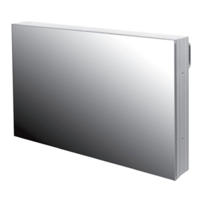
- Whenyouinstallmonitormakesurethereis at least20cmclearanceforeffective
ventilation and do not sealoff monitorsets.
If monitorsets areinstalledat thelocations of bad ventilation, theinner
temperaturecanbe raisedrapidlyand it cancausefrequentmalfunctionsand
rapidreductionoftheproductlife.
* Ventilationspacein front of monitormust be furnishedforheat dispersion.If the
front space of monitorhas to be sealed,theremust be considerationfortheheat
dispersion in therear sideof monitor.
- Regularlycleanoff theventholesin theback of monitorsets.
If theventholesand thefanair holesarecloggedwithdust,it preventsthe air
flowinsideof monitorsets.
It cancauserapidincreaseof theinnertemperatureand maycausemalfunctions.
Cleanoff theventholesand the fanair holeswith avacuum cleanerregularly.
※Clearance for Ventilation ※Cleaning and Maintenance
VacuumCleaner
WARNING
WARNING
- 6- - 7-

WarningWarning
※
Handle with Caution.
-Shock/Impact on the set's sides will result in internal
circuit damages.
-The edge/bottom of the panel are fragile.
Use shock-absorbing pads or rugs for laying down the
product.
※
Please keep following instructi
on for panel protection without
exception.
- This product can be damaged even with minor impact
for its nature.
Please keep following instruction to carry or store the
products.
PANEL PANEL PANEL
PANEL CUSHION
PANEL
•If you need to stand LCD,
•If you need to lay down
•If you need to lay down LCD
•Please do not stand LCD
•Please do not lean over
•Please do not lean over the
you must lean over the
LCD as face down
as face up position, please be
alone. It may fall or slip off
the LCD. It may damage
LCD toward the edge part. It
LCD to avoid panel touches
position, please use
cautious for falling objects
and Panel can be broken or
the bottom part of the
may damage the edge part
ground or floor .
shock-absorbing pads
on the surface of the LCD.
damaged.
LCD.
of the LCD.
under the LCD.
WARNING
WARNING
- 8- - 9-

※How to carry ※Application information
It alwaysneeds twopersonsto carry or install
monitor.
Whenyou carry monitorwith up straight
manner, pleaseholdhandleson the backand
bottompart of thepaneltogether.
Pleasebe carefulnot to touch thebottompart
of the panelwhenyouput down thepanel.
Don't carry monitorin Horizontal Status.
ÅÆ
- Changetheimagesof little luminance differencebetweenthebackground and characters,periodically.
Æ Æ Æ
-It is not recommendedto display theimagesof hugeluminancedifferencebetweenthebackground
and charactersor theimagesof greytone.
Whentwo operatorsupholdmonitor, Panelis
twistedby unbalancedhandling.
Please do not touch the panel with your hand.
If static images aredisplayed on the screen for along time, it causes burn-in image.
Please keep the following instruction to optimize the lifetime and functions of the
product.
1. Operating condition
- Temperature: 20 ±15˚C
- Humidity:55 ±20 %
- Displaypattern: movingpictureor regularswitchover display
- Environmentalcondition: Wellventilatedplaceis recommended.
- Poweroffand screen saver: Periodicalpower-offor screen saveris needed afterlong-termstatic
display.
※Note: Moving pictureor blackpatternis stronglyrecommendedfor screensaver.
2. Operating methodsto minimize burn-in imagedue to long-term static information
display
-For optimalperformance,we suggestturningofftheLEDpower on themonitorforfourhoursper day
- Periodicaldisplay contentschangefromstaticimageto moving picture.
- Periodicalbackground colorand character(image)colorchange
(X) (X)
-Scrollthecharactersperiodically.
(WholeScreen Scroll)
UA012
DEPARTURE
Flight No.
Time
Gate
UA012
11:20
A02
KE732
12:10
K17
AN291
12:45
F11
DEPARTURE
Flight No.
Time
Gate
UA012
11:20
A02
KE732
12:10
K17
AN291
12:45
F11
DEPARTURE
FlightNo.
Time
Gate
UA012
11:20
A02
DEPARTURE
FlightNo.
Time
Gate
UA012
11:20
A02
DEPARTURE
FlightNo.
Time
Gate
UA012
11:20
A02
DEPARTURE
FlightNo.
Time
Gate
UA012
11:20
A02
ARRIVAL
Flight No.
Time
Gate
Delay
AA213
9:20
K11
On time
OZ 621
11:25
G21
10 min.
JA 032
12:05
A19
On time
ARRIVAL
Flight No.
Time
Embark
Delay
AA213
9:20
NewYork
On time
OZ 621
11:25
Seoul
10 min.
JA 032
12:05
Beijing
On time
DEPARTURE
Flight No.
Time
Gate
UA012
11:20
A02
KE732
12:10
K17
AN291
12:45
F11
DEPARTURE
Flight No.
Time
Gate
UA012
11:20
A02
KE732
12:10
K17
AN291
12:45
F11
WARNING
WARNING
- 10 - - 11 -

•Avoid giving a shock or damage at LCD
corner or other parts during setting
Multi-Vision.
•Avoid that LCD is twisted.
•Keep all LCDs balanced in vertical or horizontal
force after setting Multi-Vision. Avoid LCD is set
up tilted so it can give a damage to down LCD.
•Avoid that LCD outside is shocked or
damaged by sharp thing.
Fixed
WARNING
WARNING
- 12 - - 13 -
• The load applied to all sets must be supported by the wall mount on which each set is
mounted through a VESA mount(600 x 400).
• The load must be supported only through a wall mount with a set through the VESA
wall mount. (Each set must be completely fixed to a wall or wall mount.)
Warning
※
Attention for Installing
※ Detailed installation instructions are described in our Main Frame User Manual.
■How to Adjust the MLCD gap with the Adjuster.

•Avoid giving a shock or damage at LCD
corner or other parts during setting
Multi-Vision.
•Avoid that LCD is twisted.
•Keep all LCDs balanced in vertical or horizontal
force after setting Multi-Vision. Avoid LCD is set
up tilted so it can give a damage to down LCD.
•Avoid that LCD outside is shocked or
damaged by sharp thing.
Fixed
WARNING
WARNING
- 12 - - 13 -
• The load applied to all sets must be supported by the wall mount on which each set is
mounted through a VESA mount(600 x 400, TBD).
• The load must be supported only through a wall mount with a set through the VESA
wall mount. (Each set must be completely fixed to a wall or wall mount.)
Warning
※
Attention for Installing
※ Detailed installation instructions are described in our Main Frame User Manual.
■How to Adjust the MLCD gap with the Adjuster.
•Guide for peeling off side tape caution.
•Please, Peel off side tape slowly

01. Safety Precautions
•If it operatesabnormally,stopusingit
immediately.
•Pleasereferto aspecializedconstruction
companyforinstallingstandor wall
mountunit. Otherwise, damageor injury
maybecaused.
•Avoidanyactionto damagethe power
cordor power plug. It maycausefireor
electricshock.
•Donot alter (ordisassemble) the
product. It maycauseelectricshock
sincehighvoltage isflowinginside.
•Donot placeanyliquid-containing
containeronit. If theinside iswet, it
maycauseelectricshockor fire.
•Donot touchthedevicewhen lightning
strikes.
•Donot pull out thepower plug with awet
hand. It maycauseelectricshock.
•Donot installtheproduct where it may
beexposed to direct sunlightor near
anyheatingdevice. It mayshortenthe
product'slife spanor causefailure.
•Donot put any foreignmaterialinto
theproduct. It maycauseafailureor
shortenthelifespan.
•Donot installinanunstablelocation
It maycauseinjury.
•Donot exceed ratingsofAC outlet
or extensioncords.It maycausefailure.
•Makesurethe product isnot covered
withanyobject. If the ventilationholeis
blocked, theinsidetemperature mayrise
to causeoverheatingresultinginfire.
•Do not touchproduct’sfrontsurfacewith •Do not poke the frontscreen with sharp
material.It maydamagethescreenand
maycausemalfunction of the product.
•Donot leanagainst the product or keep
it leaned. It maycauseinjury or failure. •Donot put it at any placewithmuch
humidity,dust, oil, smokeor steam. It
maycausefailure.
•If you do not want to use the product
for a long time, keep the power plug
unpluggedto saveelectricity.
•Thesocket-outlet shouldbe installed
neartheequipment and be easily
accessible.
•Donot put any heavy object onit.
It maycausefailure.
•Donot pull out or hangdownthe
connectioncable. It maydamagethe
cordto causefire or electricshock.
•Pullout the power plugbyholding the
plug. Otherwise,it maydamagethe
powercordto causefireor electric
shock.
•Donot ride or steponthe product It may
causebreakagewhenfallendown. •Whenmovingit, disconnectthe
connectingcable. Otherwise, it may
damagethecableto causefire or
electricshock.
•Installtheproduct onsafeand flat
surface.
•Donot put candlesontheproduct.If the
liquidflows insidetheproduct. It may
causeelectricshockor fire. hand. Otherwise, theimagequality can
be lowered.
- 14 - - 15 -

▶Input Ports
▶Front
▶Rear
02. Names
❶
❻
❷
❼
❸
❽
❹
❾
❺
❿
1. AC IN
AC 100V ~ 240V, 50/60Hz
2. A/S
Only for Firmware upgrade.
3. LAN
Display control via Ethernet (RJ45)
4. IR
Remote controller input port
5. RS232C IN
Display control via COM port
(D-Sub 9pin, FEMALE)
6. RS232C OUT
Display control via COM port
(D-Sub 9pin, MALE)
7. DVI IN
To input Display Port signals
8. HDMI IN
To input HDMI video signal.
9. DP IN
To input DisplayPort video signal.
10. DP OUT
For loop through video with other
monitors for sharing video signal through
DisplayPort.
- 16 - - 17 -

•Do not connect/disconnect cables while monitor or other external equipments are turned on.
•First turn off the power all the attached equipment and make connections.
•Make sure the power cord is inserted properly into the power inlet to prevent unexpected pullout of
the cord.
3.1. Connection of Single
ㆍMonitor and PC should be connected; a Com Port in a PC and RS-232C IN port in a monitor is
connected with supplied RS-232C cable.
ㆍIf you do not have Com Port, you need to use an USB converter for RS-232C. Depending on
manufacturers or models, converters may cause malfunction.
03. How to Connect Cables
ControlPC
DP Cable
HUB or Router
LANCable(Directcable)
LANCable(CrossCableor DirectCable)
RS-232C
DP Cable
HDMI Cable
DVDplayer
DVDplayer
DVDplayer
LOOP OUT
- 18 - - 19 -
DVI Cable

3.2. Connection of Multiple (for DP in)
•Image quality can be affected by cable or signal quality.
•Please use DisplayPort cable with DisplayPort certified logo.
•Select DisplayPort cables feature a locking function. When removing this cable, hold down the top
button to release the lock.
•Recommended maximum set connection for Multi setting is shown in table below.
If you need to connect more than described in the table, you have to use distributors.
3.3. Connection of Multiple (for 1:1 connection)
•It is recommended you purchase an HDMI-certified cable. Otherwise, the screen may
appear blank or a connection error may occur.
•Image quality can be affected by cable or signal quality.
VideoSource
※Caution for DP Signal Distributor
If you want to display HDCP (High-bandwidth Digital
Content Protection) applied contents, you must use
the distributor that supports HDCP function.
INPUT SOURCE
Resolution
Output Port
Connection
Remark
DP / HDMI
3840 x 2160 x 60Hz
DP OUT
6 sets
HDCP Available
DVI
1920 x 1080 x 60Hz
DP OUT
6 sets
HDCP Available
DPIN DP OUTHDMI-IINDVIIN DP IN DP INHDMI-IINDVIIN DP IN DP OUTHDMI-IINDVIIN
DPIN DPOUTHDMI-IINDVIIN DP IN DP OUTHDMI-IINDVIIN DP IN DP OUTHDMI-IINDVIIN
DPIN DP OUTHDMI-IINDVIIN DPIN DP OUTHDMI-IINDVIIN DP IN DP OUTHDMI-IINDVIIN
VIDEO Signal Distributor
VideoSource
DPIN DP OUTHDMI-IINDVIIN DP IN DP INHDMI-IINDVIIN DP IN DP OUTHDMI-IINDVIIN
DPIN DPOUTHDMI-IINDVIIN DP IN DP OUTHDMI-IINDVIIN DP IN DP OUTHDMI-IINDVIIN
DPIN DP OUTHDMI-IINDVIIN DPIN DP OUTHDMI-IINDVIIN DP IN DP OUTHDMI-IINDVIIN
HDMI DPDVI
HDMI or DP or DVI
- 20 - - 21 -

3.4. Connection of Control Cable
•Control signal transmission can be connected by 3 different methods.(RS-232C or Ethernet
or IR)
•RS-232C and Ethernet connection cannot be used simultaneously.
•All control signals are output to the RS-232OUT after conversion to RS-232C signal.
3.4.1. Connection of RS-232C Cable
•Maximum use of RS-232C with Daisy Chain connection is 30 sets or less, if you need
additional connection, use RS-232C distributor.
RS-232CcontrolPC
RS-232C Cable
LAN IR RS232CIN RS232COUT LAN IR RS232CIN RS232COUT LAN IR RS232CIN RS232COUT
3.4.2. Connection of Ethernet Cable
•In case of Ethernet connection, the control PC should be connected to one of monitor sets
with Ethernet cable.For the connection between the monitor sets, they should be
connected with RS-232C cables.
LAN IR RS232CIN RS232COUT LAN IR RS232CIN RS232COUT LAN IR RS232CIN RS232COUT
EthernetcontrolPC
HUB or Router(
Wireless&Cable)
LANCable
(DirectCable)
LANCable(
DirectCable)
LANCable(CrossCableor DirectCable)
- 22- - 23-

4. ID Setting
•Refer to the next chapter for OSW use.(6.1 ~ 6.7)
•Before ID Setting Using OSW, Make sure that all of the connected MLCD sets are turned on by
clicking “Power On” button in Broadcast.
4.1. Sequential Connection
ㆍIt is the sequential RS-232C cable connection according to the order of ID numbers.
LA
NI
RRS232
C IN RS232C
OUT
LA
NI
RRS232
C IN RS232C
OUT
LA
NI
RRS232
C IN RS232C
OUT
LAN
I
R
RS232
C IN RS232C
OUT
LA
NI
RRS232
C IN RS232C
OUT
LA
NI
RRS232
C IN RS232C
OUT
LA
NI
RRS232
C IN RS232C
OUT
LA
NI
RRS232
C IN RS232C
OUT
LA
NI
RRS232
C IN RS232C
OUT
ID 1 ID 2 ID 3
ID 4 ID 5 ID 6
ID 7 ID 8 ID 9
RS-232C
control PC
RS-232C
1.Go to “APPLICATION” tab and Click “ID SETTING” icon.
2. Click “AUTO ID SET” button in “ID” tab to run ID setting automatically.
3. After that, ID setting status in OSW Screen Configuration is as bellow. It's same as physical
RS-232C cable connection. Because "AUTO ID" sets the order of ID numbers according to
the sequential RS-232C cable connection.
BROADCASE MODE
ID 1
ID 4
ID 7
ID 2
ID 5
ID 8
ID 3
ID 6
ID 9
- 24 - - 25 -

4.2. Random Connection
ㆍIt is the random RS-232C cable connection regardless of the order of ID numbers.
RS-232C
control PC
LA
NI
RRS232
C IN RS232C
OUT
LA
NI
RRS232
C IN RS232C
OUT
LA
NI
RRS232
C IN RS232C
OUT
LA
NI
RRS232
C IN RS232C
OUT
LA
NI
RRS232
C IN RS232C
OUT
LA
NI
RRS232
C IN RS232C
OUT
LA
NI
RRS232
C IN RS232C
OUT
LA
NI
RRS232
C IN RS232C
OUT
LA
NI
RRS232
C IN RS232C
OUT
RS-232C
1.Go to “APPLICATION” tab and Click “ID SETTING” icon.
2.Select another number, which is not in use, for “AUTO GROUP ID" and click "AUTO
ID SET" in “AUTO ID” menu
3. After that, ID setting status in OSW PANEL window is as follows. It's same as physical RS-
232C cable connection. Because "AUTO ID" sets the order of ID numbers according to the
sequential RS-232C cable connection.
* GID = Group ID, MID = Monitor ID
GID 2
MID 3
GID 2
MID 2
GID 2
MID 1
GID 2
MID 4
GID 2
MID 5
GID 2
MID 6
GID 2
MID 9
GID 2
MID 8
GID 2
MID 7
ID 1
ID 4
ID 7
ID 2
ID 5
ID 8
ID 3
ID 6
ID 9
- 26 - - 27 -

4.Identify the IDs of all connected MLCD sets by clicking "INFO" button in Broadcast.
5.first, Identify the IDs of upper left corner MLCD set.
6.Set the IDs identified through the above 4,5) procedure for "EXISTING GROUP/MULTI ID” in
“Modify ID” Menu. And then, set “NEW GROUP ID" as 1 and “NEW MULTI ID" as 1 in “Modify
ID" Menu. And click "SET" button in “Modify ID” menu.
7.Identify the IDs on the right MLCD set of upper left corner MLCD set in the same way as the
above 4) procedure.
8.Set the IDs identified through the above 7) procedure for "EXISTING GROUP/MULTI ID” in
“Modify ID” Menu. And then, Increase the number by 1 for “NEW MULTIID" in “Modify ID”
Menu to set the ID order. and click "SET" button in “Modify ID” menu.
GID 2
MID 3
GID 2
MID 2
GID 2
MID 1
GID 2
MID 4
GID 2
MID 5
GID 2
MID 6
GID 2
MID 9
GID 2
MID 8
GID 2
MID 7
GID 1
MID 1
GID 2
MID 2
GID 2
MID 1
GID 2
MID 4
GID 2
MID 5
GID 2
MID 6
GID 2
MID 9
GID 2
MID 8
GID 2
MID 7
Group ID 2, Multi ID 3 Group ID 1, Multi ID 1
GID 1
MID 1
GID 2
MID 2
GID 2
MID 1
GID 2
MID 4
GID 2
MID 5
GID 2
MID 6
GID 2
MID 9
GID 2
MID 8
GID 2
MID 7
GID 1
MID 1
GID 2
MID 2
GID 2
MID 1
GID 1
MID 2
GID 2
MID 5
GID 2
MID 6
GID 2
MID 9
GID 2
MID 8
GID 2
MID 7
Group ID 2, Multi ID 4 Group ID 1, Multi ID 2
- 28 - - 29 -

9.Repeat the above 7) and 8) procedures for the rest of displays in the same order as the
number of the 10) procedure's capture view.
10.After setting last MLCD set, ID setting status in MSCS Screen Configuration is as follows. It's
different from physical RS-232C cable connection.
ID 1
ID 4
ID 7
ID 2
ID 5
ID 8
ID 3
ID 6
ID 9
Current Group ID
New Group ID
2
→
1
Current Group ID
New Group ID
3
→
1
4
→
2
9
→
3
2
→
4
5
→
5
8
→
6
1
→
7
6
→
8
7
→
9
4.3. Using Auto Setting
ㆍThis feature is a way to automatically set the ID by entering a cable connection order
※ NOTE : This function is supported on OSW 2.1.3 and later versions.
1. Monitor Configuration
ㆍEnter the horizontal and vertical numbers in the X / Y fields. Click the SET button.
- 30 - - 31 -

2. Monitor Configuration
•Type the number in panel as physical RS-232 cable connection sequence. 3. Auto Setting Start
• After typing the numbers in auto setting panel, then click the START button.
RS-232CcontrolPC
RS-232C Cable
LA
N
IR RS232CI
N
RS232CO
UT
LA
N
IR RS232CI
N
RS232CO
UT
LA
N
IR RS232CI
N
RS232CO
UT
LA
N
IR RS232CI
N
RS232CO
UT
LA
N
IR RS232CI
N
RS232CO
UT
LA
N
IR RS232CI
N
RS232CO
UT
LA
N
IR RS232CI
N
RS232CO
UT
LA
N
IR RS232CI
N
RS232CO
UT
LA
N
IR RS232CI
N
RS232CO
UT
•If the physical connection is above, type the number in auto setting panel as connection
sequence.
• Setting is done, you can see IDs set as below.
ID 1
ID 2
ID 3
ID 4
ID 5
ID 6
ID 7
ID 8
ID 9
- 32 - - 33 -

5.1. Picture Menu
ㆍUse this menu to activate Brightness/Contrast/sharpness and the luminance of the
backlight adjustment.
5. OSD Menu
[Input Menu Table]
[Picture Menu Table]
5.2. Input Menu
ㆍUse the Input Source menu to select between different video inputs that are be connected to the
monitor.
Menu
Sub Menu
Description
Range
Picture
Backlight
Backlight adjusts the luminance of the backlight
0 ~ 100
Brightness
Brightness adjusts the brightness of the monitor.
0 ~ 100
Contrast
Contrast adjusts the difference between darkness and lightness
on the monitor. Adjust the Brightness first, and then adjust
Contrast only if further adjustment is necessary.
0 ~ 100
Sharpness
Sharpness adjusts the sharpness of the monitor
0~4
GAMMA
Select a display gamma for best picture quality.
1.8/2.0/
2.2/2.4
TEMPERATURE
Adjust the color temperature of the screen. If Color Temperature
needs further adjustment, the individual R/G/B levels of the white
point can be adjusted. Can be used only in User mode of Color
Temperature.
10000/
9300/
6500/
3200/
USER
HUE
Adjustment the hue value of the screen.
0 ~ 100
SAT
Adjustment the saturation value of the screen.
0 ~ 100
Color Range
Select Color Range for input signal Only applied to HDMI, DVI).
The color range of DP is detected Automatically
Limit/Full
Menu
Sub Menu
Description
Range
Input
DP
Select DP input when you are using the DP (DisplayPort) connector.
-
HDMI
Select the HDMI input when you are using the HDMI connector.
Use to select the HDMI input source.
-
DVI
Select DVI input when you are using the DVI connector.
-
- 34 - - 35 -
Picture Input
Backlight Brightness Contrast Sharpness
Multi-Display
MUL
TI
Other Picture Input Multi-Display
MUL
TI
Other
DP HDMI DVI
Table of contents
Other Orion Monitor manuals

Orion
Orion 185LEDA User manual

Orion
Orion MIS-4220 User manual

Orion
Orion 430LED4K User manual

Orion
Orion VALUE SERIES User manual

Orion
Orion OLMU-K4940 User manual

Orion
Orion OLS-3201PGB User manual

Orion
Orion OLME-5550S User manual

Orion
Orion LS3200 User manual

Orion
Orion PREMIUM WIDE SERIES User manual

Orion
Orion Premium Line 097RTH User manual

Orion
Orion VALUE SERIES User manual

Orion
Orion OPM-4260 User manual

Orion
Orion 17" TFT-LCD MONITOR User manual

Orion
Orion ODC-10000 User manual

Orion
Orion OLMU-5520 User manual

Orion
Orion 20PVM User manual

Orion
Orion Digital information display User manual

Orion
Orion 9REDP User manual

Orion
Orion ORL1850W User manual

Orion
Orion 20" User manual