Orion OPM-4260 User manual

A revolutionary MPDP
Infinitely Expandable MPDP
Thank you for purchasing our MPDP.
Please read through this user's manual for safety before installing this product.
This product is manufactured for Multi Plasma display model only.
User’s Manual

1
2
Infinitely expandable
1 2
Contents
User's Manual Multi-Screen Control
System(MSCS) Guide Pin(4pcs) Handle (2 pcs)
RS232 Cable Bolt (4 pcs)
DVI-D Cable Power Cable
Wall mounting Unit
(refer to page 8)
Stand Unit
(refer to page 7)
RS-232C Distributor
Necessary for connecting more than 10 units.
1 Input, 6 Output
Supplied Accessories
Optional Accessories
1. Safety Precautions ..................................................................................................3
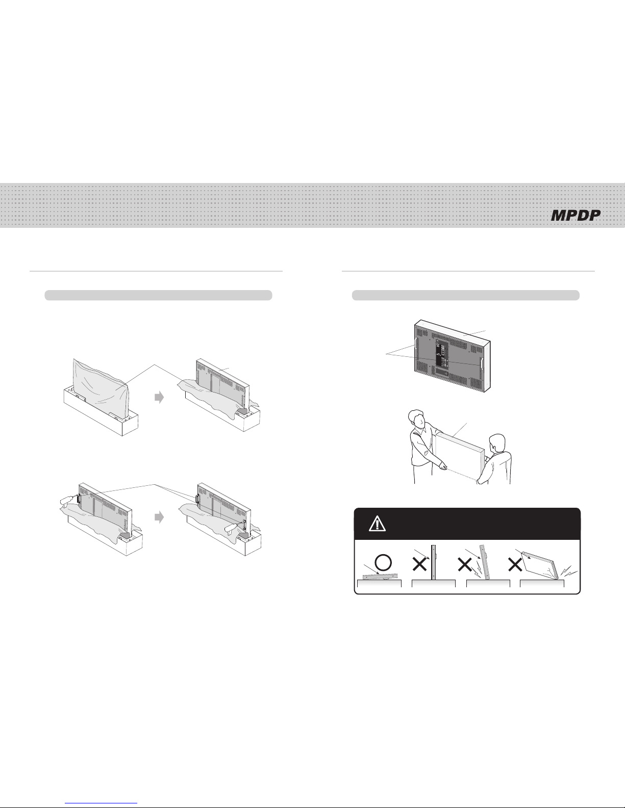
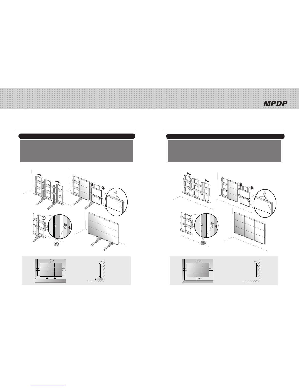
2. How to Install ..............................................................................................................5
3. Guidance for Users ................................................................................................9
4. How to Connect Cables ....................................................................................11
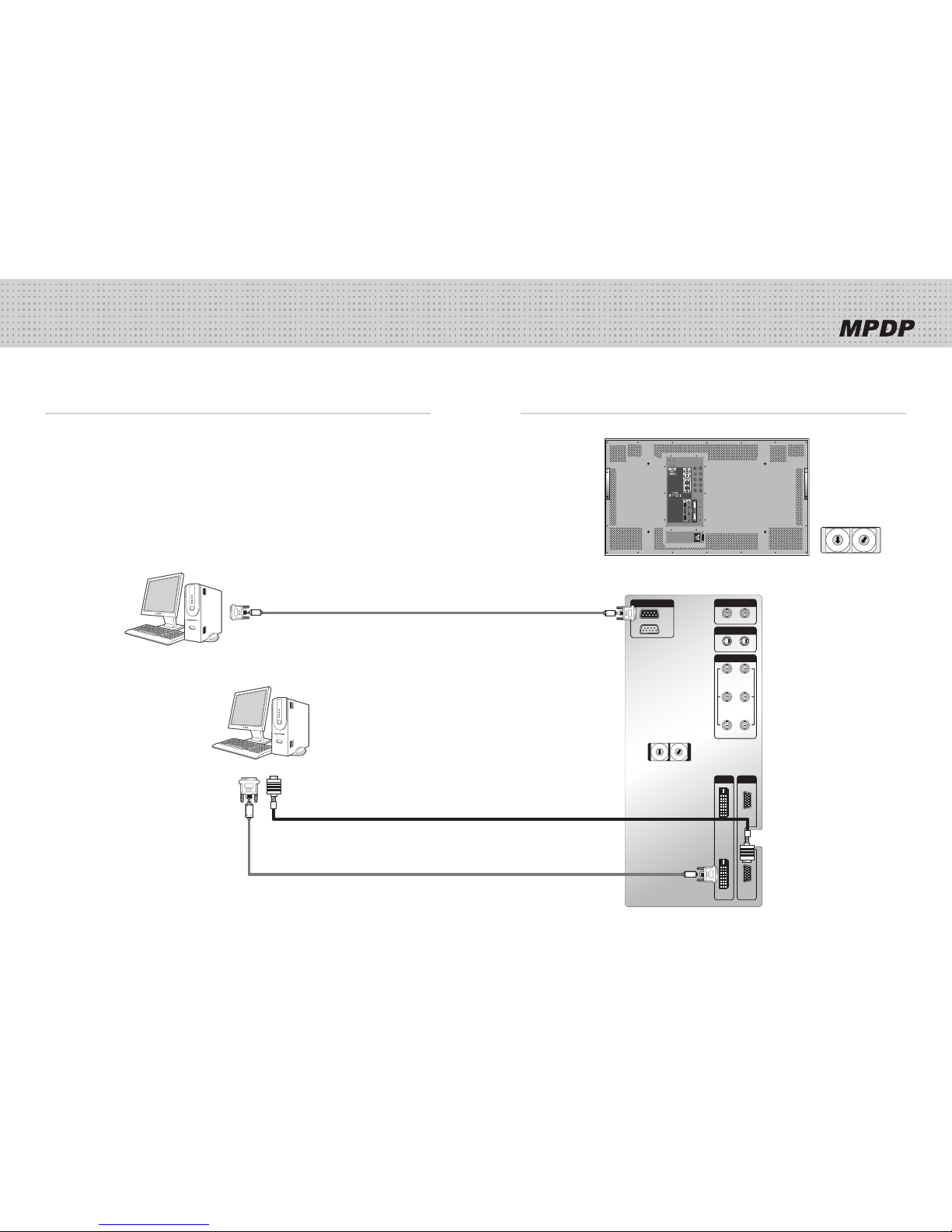
4.1. Connection of one set MPDP .................................................................................11
PC & DVI Connection .............................................................................................11
VCR Connection ......................................................................................................13
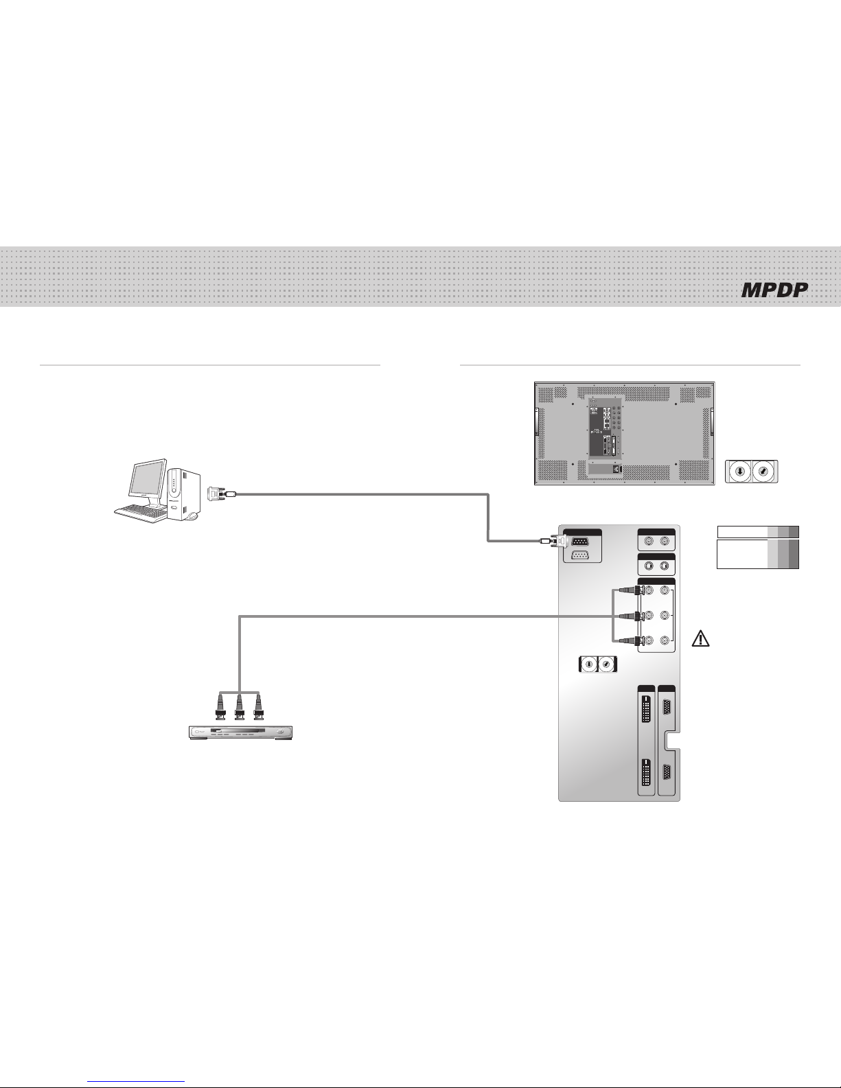
DVD Player & DTV Set top box connection .........................................................15
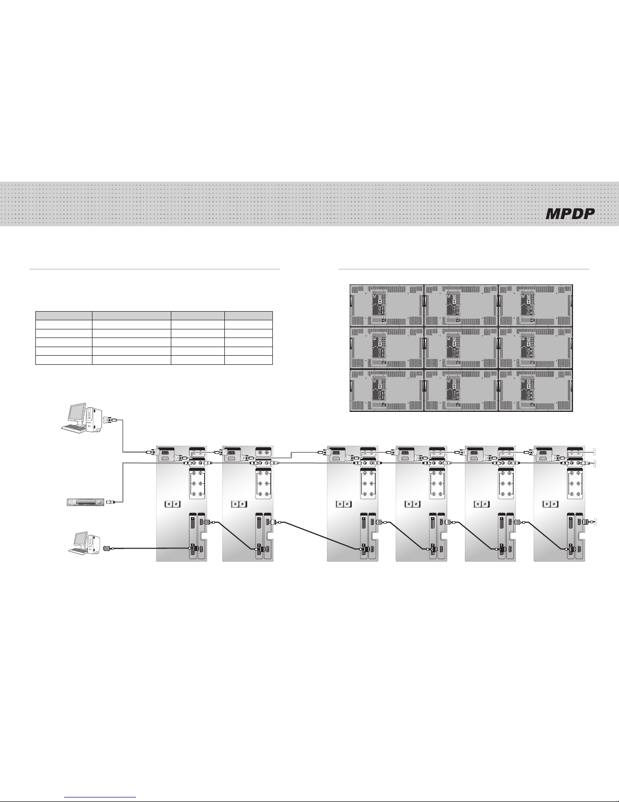
4.2. Connection of Multi-screen MPDP ........................................................................17
4.3. Connection of RS-232C Cable ..............................................................................19
4.4. Connection of 3 x 3 MPDP .....................................................................................20
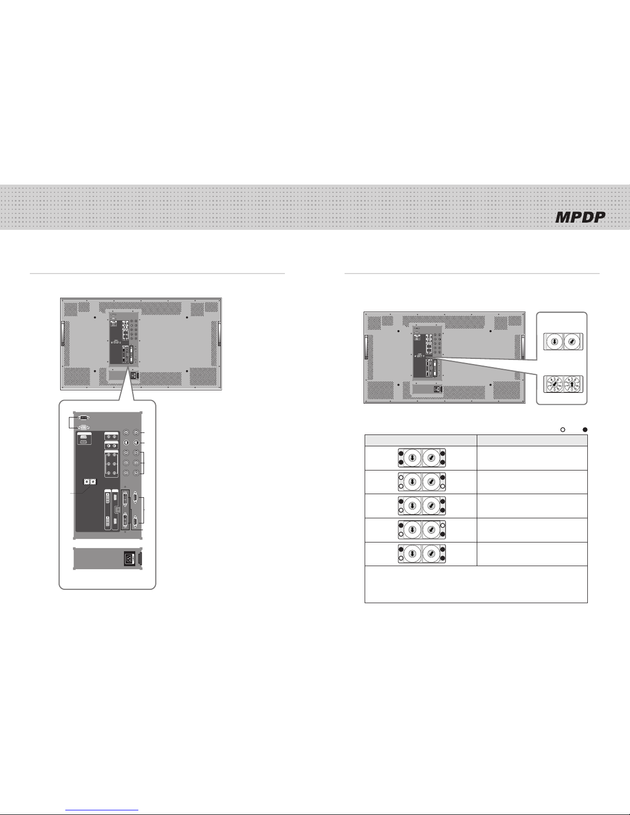
4.5. ID setting of X x Y MPDP ........................................................................................21
5. Setting and operation of MSCS ....................................................................22
5.1. Setting 'Com Port' ....................................................................................................23
5.2. "Last design/New design" setting ..........................................................................23
5.3. Setting 'Multi-Screen' Configuration .......................................................................24
5.4. MSCS Instruction ....................................................................................................25
5.5. ID Setting ..................................................................................................................25
5.6. Configuration of various modes .............................................................................26
5.7. Setting multi screens at a time ...............................................................................27
5.8. Slide Control .............................................................................................................28
5.9. MSCS Size Control ...................................................................................................30
5.10. PDP Control ............................................................................................................31
5.11. Screen control ........................................................................................................32
5.12. Auto Tracking ........................................................................................................33
5.13. Setting "Timer On/Off" ...........................................................................................34
5.14. Broadcast On .........................................................................................................35
5.15. Orion PDP Home Page logon and Version information .....................................36
6. MSCS Protocol .......................................................................................................37
7. Other tips ....................................................................................................................41
7.1. Before calling for service ........................................................................................41
7.2. About Plasma display panel ...................................................................................42
8. Resolution of PC video signal .......................................................................43
8.1. DVD / DTV ...............................................................................................................43
8.2. PC & DVI...................................................................................................................43
9. Specifications ...........................................................................................................44
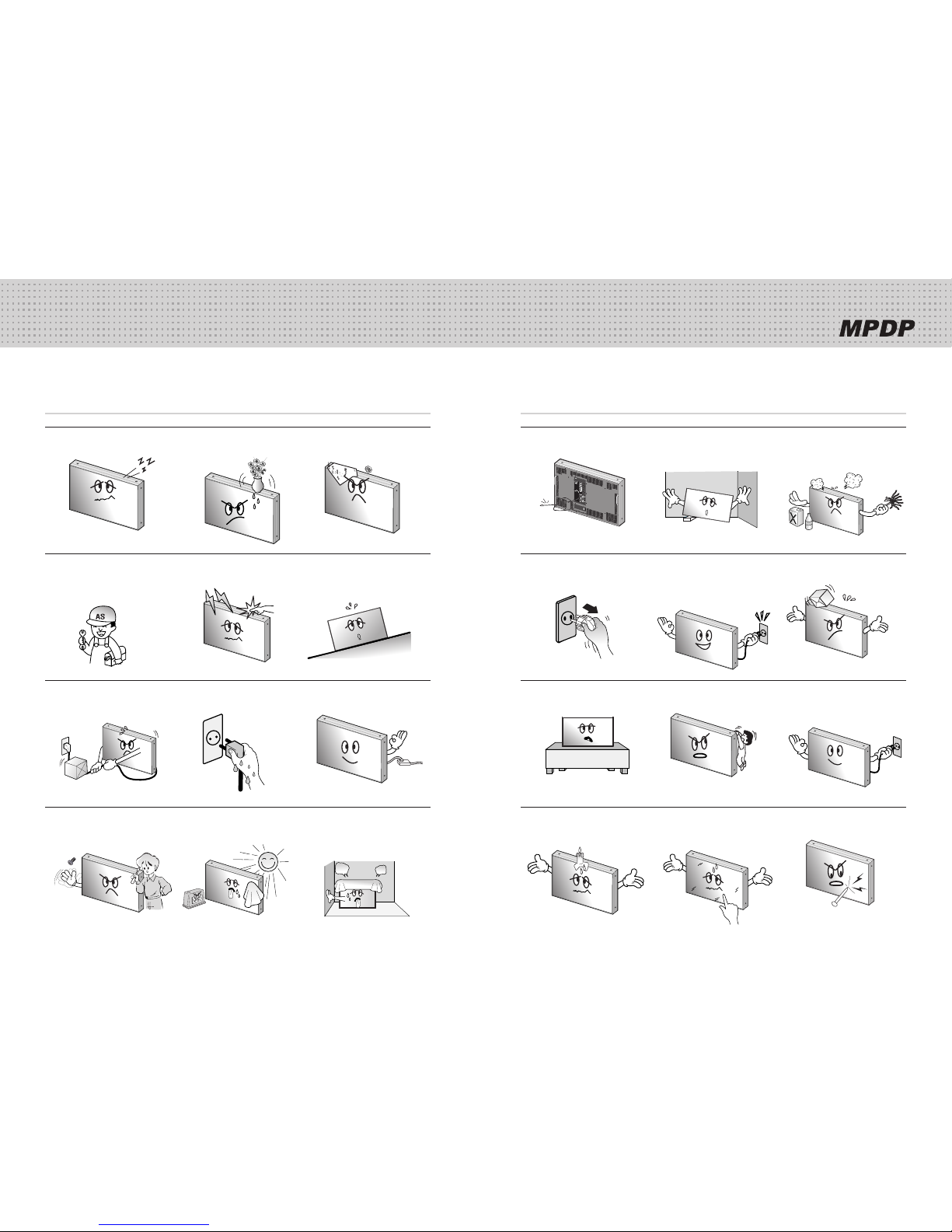
If you fail to comply with the regulations for safety and proper use,
fire or injury may be caused.
Warning
Features of MPDP
▶Enjoy a wide flat screen with high brightness and high quality.
▶Easy to install and move due to its thin design
▶ Enjoy your favorite programs with various split-screen features simultaneously presenting
several programs.
Thank you for purchasing our MPDP monitor.
This manual describes how to use the product and notes in use.
Please read the manual carefully before using it.
After reading this manual, please retain for future reference.
If you have any questions or a problem occurs, please contact either the company you purchased this
product from or an authorized service center.
※Displaying static picture for an extended period of time may cause an afterimage effect.
Notice to users
Class A digital device
It is a device designed for business purpose with a safety certificate for electromagnetic interference, which
user should be mindful of.

3
4
Infinitely expandable
3 4
1. Safety Precautions
Do not poke the front screen with sharp•
material. It may damage the screen and
may cause malfunction of the product.
Do not lean against the product or keep•
it leaned. It may cause injury or failure.
Do not put it at any place with much•
humidity, dust, oil, smoke or steam. It
may cause failure.
If you do not want to use the product•
for a long time, keep the power plug
unplugged to save electricity.
The socket-outlet should be installed•
near the equipment and be easily
accessible.
Do not put any heavy object on it.•
It may cause failure.
Do not pull out or hang down the•
connection cable. It may damage the
cord to cause fire or electric shock.
Pull out the power plug by holding the•
plug. Otherwise, it may damage the
power cord to cause fire or electric
shock.
Do not ride or step on the product It may•
cause breakage when fallen down.
When moving it, disconnect the•
connecting cable. Otherwise, it may
damage the cable to cause fire or
electric shock.
Install the product on safe and flat•
surface.
Do not put candles on the product. If the•
liquid flows inside the product. It may
cause electric shock or fire.
Do not touch product’s front surface with•
hand. Otherwise, the image quality can
be lowered.
If it operates abnormally, stop using it•
immediately.
Please refer to a specialized•
construction company for installing stand
or wall mount unit. Otherwise, damage
or injury may be caused.
Avoid any action to damage the power•
cord or power plug. It may cause fire or
electric shock.
Do not alter (or disassemble) the•
product. It may cause electric shock
since high voltage is flowing inside.
Do not place any liquid-containing•
container on it. If the inside is wet, it
may cause electric shock or fire.
Do not touch the device when lightning•
strikes.
Do not pull out the power plug with a wet•
hand. It may cause electric shock.
Do not install the product where it may•
be exposed to direct sunlight or near
any heating device. It may shorten the
product's life span or cause failure.
Do not put any foreign material into•
the product. It may cause a failure or
shorten the life span.
Do not install in an unstable location•
It may cause injury.
Do not exceed ratings of AC outlet•
or extension cords. It may cause failure.
Make sure the product is not covered•
with any object. If the ventilation hole is
blocked, the inside temperature may rise
to cause overheating resulting in fire.

5
6
Infinitely expandable
5 6
2. How to Install
How to assemble handles
Install this set only at a location where adequate ventilation is available. y
1. Product is packed in a box as shown in Figure 1.
2. Please carefully remove the Packing Bag with a knife or a pair of scissors.
※ Please check front and rear side before you cut the bag to prevent any damages
on panel or set.
3. Please assemble handles with the bolts that are in the accessory box to the
rear side as shown in the figure.
How to move MPDP
1. 2 people hold each handle on product’s back side.
2. 2 people transfer the product with holding the handle and the front part at
the same time.
※Attention : Do not remove the panel protection pad until a set is completely installed on a stand or a wall hanger.
Please carefully remove Panel protection pad to prevent any damages on the product .
handles
handles
Attention
※Do not incline the panel forward.
The edge or bottom of the panel can be damaged.
When you need to lay a set down on the floor, please use shock-
absorbing pads or rug beneath the set.
PANEL
PANEL
PANEL PANEL
Packing Bag
[Figure 1]
[Figure 3]
[Figure 2]
[Figure 4]
Panel protection
Panel protection
Panel protection

7
8
Infinitely expandable
Hanger
Hanger Bolt
PDP
Hanger
Guide Pin
Install on a Stand
Please secure minimum clearance as shown in the picture for adequate ventilation and technical service.
Stand Unit (Option)
The set can be installed as shown below. y
(For further information, refer to the optional 'Stand Installation and Setup Guide'.)
Hanger Bolt
PDP
Stand Stand
Guide Pin
Wall Mounting Unit (Option)
The set can be installed on the wall as shown below. y
(For further information, refer to the optional 'Wall Mounting Bracket Installation and Setup Guide'.)
Mount on the wall
Please secure minimum clearance as shown in the picture for adequate ventilation and technical service.
Please do not install our product at following locations to protect the product and y
prevent possible malfunction.
- Places of vibration or shock: PDP set may fall and damaged
- Next or near to Sprinkler sensors: The sensors may detect heat from a set and sprinkler can be activated.
- Around high voltage power lines: Noise from the power line may affect screen images
- Around heating apparatus: PDP set may be overheated and damaged.
Please check the ystability of wall.
If the wall is not strong enough, reinforce the wall before installation.
Please connect all the cables to proper ports in a set before installation. y

9
10
Infinitely expandable
9 10
3. Guidance for Users
Input/Output Terminals
0
1
2
3
4
5
6
7
8
9
0
1
2
3
4
5
6
7
8
9
RS-232C VIDEO
IN OUT
IN
OUT
S-VIDEO
IN OUT
COMPONENT
IN OUT
Y
Pb
Pr
DVI-D PC
IN
IN
OUT
OUT
ID SELECT
M-ON
M-STB S-ON
FA N
❶
❷
❸
❹
❺
❻
❼
❽
1. RS-232C
MPDP Control, Firmware Upgrade, 9pin D-sub
2. Video
Composite Signal
NTSC, PAL, SECAM
3. S-Video
S-Video Signal
NTSC, PAL, SECAM, 4pin Mini Din
4. Component
DVD Signal
DTV - YPbPr Signal
5. PC
Computer RGB Analog Signal, D-sub 15pin
6. DVI-D
TMDS Signal
7. ID Switch
Set ID Switch
8. AC Input
AC 100V ~240V, 50/60Hz
Set ID Switch Setting
Example of ID Switch setting y
- You can set ID with 2 rotary switches as shown in the following figure.
[PDP ID 01]
0
1
2
3
4
5
6
7
8
9
0
1
2
3
4
5
6
7
8
9
[PDP ID 15]
LED Indication y
LED ON OFF
10 digit single digit
LED Indication Description
0
1
2
3
4
5
6
7
8
9
0
1
2
3
4
5
6
7
8
9
M-ON
M-STB
FAN
S-ON No Power.
0
1
2
3
4
5
6
7
8
9
0
1
2
3
4
5
6
7
8
9
M-ON
M-STB
FAN
S-ON Internal System Check after Power on.
0
1
2
3
4
5
6
7
8
9
0
1
2
3
4
5
6
7
8
9
M-ON
M-STB
FAN
S-ON System ready.
0
1
2
3
4
5
6
7
8
9
0
1
2
3
4
5
6
7
8
9
M-ON
M-STB
FAN
S-ON
Power ON by MSCS Program.
(M-ON and S-ON blink simultaneously with 1
second interval)
0
1
2
3
4
5
6
7
8
9
0
1
2
3
4
5
6
7
8
9
M-ON
M-STB
FAN
S-ON
Power Off by MSCS Program.
(System ready).
Remark)
M-ON(Master-ON) : IP Board Master Power On.
FAN : FAN Power On
M-STB(Master- Stand By) : IP Board Master Ready
S-ON(Slave-ON) : IP Board Slave Ready

11
12
Infinitely expandable
11 12
4. How to Connect Cables
4.1. Connection of one set MPDP
PC & DVI Connection
MPDP and PC should be connected; a Com Port in a PC and RS-232C IN port in a y
MPDP is connected with supplied RS-232C cable.
MPDP On/Off or Screen adjustment can be controlled by MSCS (Multi-Screen Control y
System).
ID setting on the backside of MPDP must be identical with the ID setting in MSCS to y
control MPDP with a PC.
If you do not have Com Port, you need to use an USB converter for RS-232. Depending y
on manufacturers or models, converters may cause malfunction.
PC
0
1
2
3
4
5
6
7
8
9
0
1
2
3
4
5
6
7
8
9
RS-232C VIDEO
IN OUT
IN
OUT
S-VIDEO
IN OUT
COMPONENT
IN OUT
Y
Pb
Pr
DVI-D PC
IN
IN
OUT
OUT
ID SELECT
M-ON
M-STB S-ON
FAN
[PDP ID 1]
ID switch must be set as ID 1 y
for one set use.
0
1
2
3
4
5
6
7
8
9
0
1
2
3
4
5
6
7
8
9
PC (MSCS) to control MPDP
RS-232C (Maximum 15m)
PC- analog connection (Maximum 5m)
DVI connection (Maximum 5m)
※ If you need longer connection, please use
DVI boosters or DVI fiber-optic cable.

13
14
Infinitely expandable
13 14
0
1
2
3
4
5
6
7
8
9
0
1
2
3
4
5
6
7
8
9
RS-232C VIDEO
IN OUT
IN
OUT
S-VIDEO
IN OUT
COMPONENT
IN OUT
Y
Pb
Pr
DVI-D PC
IN
IN
OUT
OUT
ID SELECT
M-ON
M-STB S-ON
FAN
VCR Connection
PC(MSCS) to control MPDP
VCR
RS-232C (Maximum 15m)
S-Video connection (Maximum 5m)
Video connection (Maximum 5m)
[PDP ID 1]
ID switch must be set as ID 1 y
for one set use.
0
1
2
3
4
5
6
7
8
9
0
1
2
3
4
5
6
7
8
9

15
16
Infinitely expandable
15 16
0
1
2
3
4
5
6
7
8
9
0
1
2
3
4
5
6
7
8
9
RS-232C VIDEO
IN OUT
IN
OUT
S-VIDEO
IN OUT
COMPONENT
IN OUT
Y
Pb
Pr
DVI-D PC
IN
IN
OUT
OUT
ID SELECT
M-ON
M-STB S-ON
FAN
DVD Player & DTV Set top box connection
In case input source is DVD, select DVD/SD in MSCS main screen. y
In case input source is DTV, select HD in MSCS main screen. y
PC(MSCS) to control MPDP
DVD Player & DTV Set top box
RS-232C (Maximum 15m)
Component connection (Maximum 5m)
[PDP ID 1]
ID switch must be set as ID 1 y
for one set use.
0
1
2
3
4
5
6
7
8
9
0
1
2
3
4
5
6
7
8
9
• According to manufacturers, the indication
of DVD Component output port may vary; “Y,
PB, PR”, “Y, B-Y, R-Y” or “Y, CB, CR.”
• Component Input ports
You can get better image quality by
connecting DVD player to component input
ports as below.
Component ports of
the set Y Pb Pr
Video output ports
of DVD player
Y Pb Pr
Y B-Y R-Y
Y Cb Cr
• Caution for Component connection
In case component cables are not properly
connected, you may have bluish or redish
screen or even no screen images.
Caution

17
18
Infinitely expandable
0
1
2
3
4
5
6
7
8
9
0
1
2
3
4
5
6
7
8
9
RS-232C VIDEO
IN OUT
IN
OUT
S-VIDEO
IN OUT
COMPONENT
IN OUT
Y
Pb
Pr
DVI-D PC
IN
IN
OUT
OUT
ID SELECT
M-ON
M-STB S-ON
FAN
0
1
2
3
4
5
6
7
8
9
0
1
2
3
4
5
6
7
8
9
RS-232C VIDEO
IN OUT
IN
OUT
S-VIDEO
IN OUT
COMPONENT
IN OUT
Y
Pb
Pr
DVI-D PC
IN
IN
OUT
OUT
ID SELECT
M-ON
M-STB S-ON
FAN
0
1
2
3
4
5
6
7
8
9
0
1
2
3
4
5
6
7
8
9
RS-232C VIDEO
IN OUT
IN
OUT
S-VIDEO
IN OUT
COMPONENT
IN OUT
Y
Pb
Pr
DVI-D PC
IN
IN
OUT
OUT
ID SELECT
M-ON
M-STB S-ON
FAN
0
1
2
3
4
5
6
7
8
9
0
1
2
3
4
5
6
7
8
9
RS-232C VIDEO
IN OUT
IN
OUT
S-VIDEO
IN OUT
COMPONENT
IN OUT
Y
Pb
Pr
DVI-D PC
IN
IN
OUT
OUT
ID SELECT
M-ON
M-STB S-ON
FAN
0
1
2
3
4
5
6
7
8
9
0
1
2
3
4
5
6
7
8
9
RS-232C VIDEO
IN OUT
IN
OUT
S-VIDEO
IN OUT
COMPONENT
IN OUT
Y
Pb
Pr
DVI-D PC
IN
IN
OUT
OUT
ID SELECT
M-ON
M-STB S-ON
FAN
0
1
2
3
4
5
6
7
8
9
0
1
2
3
4
5
6
7
8
9
RS-232C VIDEO
IN OUT
IN
OUT
S-VIDEO
IN OUT
COMPONENT
IN OUT
Y
Pb
Pr
DVI-D PC
IN
IN
OUT
OUT
ID SELECT
M-ON
M-STB S-ON
FAN
17 18
4.2. Connection of Multi-screen MPDP
RS-232C
S-VIDEO
PC
Recommended maximum set connection for Multi setting is shown in table below. y
If you need to connect more than described in the table, you have to use distributors.
Image quality can be affected by cable or signal quality. y
INPUT SOURCE Resolution Connection Remark
DVI 1600 x 1200 x 60HZ 5 sets
PC 8.2. PC & DVI Resolution Reference 2 sets 43 page
DTV 720p, 1080i 5 sets
DVD 480i, 480p, 576i, 576p 6 sets
VIDEO/S-VIDEO NTST, PAL, SECAM 6 sets
PDP1 PDP2 PDP3 PDP4 PDP5 PDP6
PC (MSCS) to control
MPDP

19
20
Infinitely expandable
20
4.4. Connection of 3 x 3 MPDP4.3. Connection of RS-232C Cable
Maximum use of RS-232 with Daisy Chain connection is y10 or less.
If you need additional connection, use RS-232 distributor.
ID 1
ID 4
ID 7
ID 2
ID 5
ID 8
ID 3
ID 6
ID 9
RS-232C
IN
OUT
PC
IN
OUT
RS-232C
IN
OUT
PC
IN
OUT
RS-232C
IN
OUT
PC
IN
OUT
RS-232C
IN
OUT
PC
IN
OUT
RS-232C
IN
OUT
PC
IN
OUT
RS-232C
IN
OUT
PC
IN
OUT
RS-232C
IN
OUT
PC
IN
OUT
RS-232C
IN
OUT
PC
IN
OUT
RS-232C
IN
OUT
PC
IN
OUT
RS-232C control PC PC
PC Signal Distributor
(UXGA : over 250MHz)
ID 1
ID 6
ID 11
ID 2
ID 7
ID 12
ID 3
ID 8
ID 13
ID 4
ID 9
ID 14
ID 5
ID 10
ID 15
ID 16
ID 21
ID 17
ID 22
ID 18
ID 23
ID 19
ID 24
ID 20
ID 25
RS-232C
IN
OUT
RS-232C
IN
OUT
RS-232C
IN
OUT
RS-232C
IN
OUT
RS-232C
IN
OUT
RS-232C
IN
OUT
RS-232C
IN
OUT
RS-232C
IN
OUT
RS-232C
IN
OUT
RS-232C
IN
OUT
RS-232C
IN
OUT
RS-232C
IN
OUT
RS-232C
IN
OUT
RS-232C
IN
OUT
RS-232C
IN
OUT
RS-232C
IN
OUT
RS-232C
IN
OUT
RS-232C
IN
OUT
RS-232C
IN
OUT
RS-232C
IN
OUT
RS-232C
IN
OUT
RS-232C
IN
OUT
RS-232C
IN
OUT
RS-232C
IN
OUT
RS-232C
IN
OUT
RS-232C Distributor
RS-232C control PC

21
22
Infinitely expandable
21
4.5. ID setting of X x Y MPDP
Identity number (ID) indicates the location of each MPDP. y
When you look at the MPDP screens in front of MPDP. y
Recommended ID of X x Y screens
ID 1 ID 2 ID 3 ID 4 ID 5
ID 6 ID 7 ID 8 ID 9 ID 10
ID 11 ID 12 ID 13 ID 14 ID 15
ID 16 ID 17 ID 18 ID 19 ID 20
ID 21 ID 22 ID 23 ID 24 ID 25
0
1
2
3
4
5
6
7
8
9
0
1
2
3
4
5
6
7
8
9
0
1
2
3
4
5
6
7
8
9
0
1
2
3
4
5
6
7
8
9
0
1
2
3
4
5
6
7
8
9
0
1
2
3
4
5
6
7
8
9
0
1
2
3
4
5
6
7
8
9
0
1
2
3
4
5
6
7
8
9
0
1
2
3
4
5
6
7
8
9
0
1
2
3
4
5
6
7
8
9
0
1
2
3
4
5
6
7
8
9
0
1
2
3
4
5
6
7
8
9
0
1
2
3
4
5
6
7
8
9
0
1
2
3
4
5
6
7
8
9
0
1
2
3
4
5
6
7
8
9
0
1
2
3
4
5
6
7
8
9
0
1
2
3
4
5
6
7
8
9
0
1
2
3
4
5
6
7
8
9
0
1
2
3
4
5
6
7
8
9
0
1
2
3
4
5
6
7
8
9
0
1
2
3
4
5
6
7
8
9
0
1
2
3
4
5
6
7
8
9
0
1
2
3
4
5
6
7
8
9
0
1
2
3
4
5
6
7
8
9
0
1
2
3
4
5
6
7
8
9
0
1
2
3
4
5
6
7
8
9
0
1
2
3
4
5
6
7
8
9
0
1
2
3
4
5
6
7
8
9
0
1
2
3
4
5
6
7
8
9
0
1
2
3
4
5
6
7
8
9
0
1
2
3
4
5
6
7
8
9
0
1
2
3
4
5
6
7
8
9
0
1
2
3
4
5
6
7
8
9
0
1
2
3
4
5
6
7
8
9
0
1
2
3
4
5
6
7
8
9
0
1
2
3
4
5
6
7
8
9
0
1
2
3
4
5
6
7
8
9
0
1
2
3
4
5
6
7
8
9
0
1
2
3
4
5
6
7
8
9
0
1
2
3
4
5
6
7
8
9
0
1
2
3
4
5
6
7
8
9
0
1
2
3
4
5
6
7
8
9
0
1
2
3
4
5
6
7
8
9
0
1
2
3
4
5
6
7
8
9
0
1
2
3
4
5
6
7
8
9
0
1
2
3
4
5
6
7
8
9
0
1
2
3
4
5
6
7
8
9
0
1
2
3
4
5
6
7
8
9
0
1
2
3
4
5
6
7
8
9
0
1
2
3
4
5
6
7
8
9
PDP ID
1
PDP ID
2
PDP ID
3
PDP ID
4
PDP ID
5
PDP ID
6
PDP ID
7
PDP ID
8
PDP ID
9
PDP ID
10
PDP ID
11
PDP ID
12
PDP ID
13
PDP ID
14
PDP ID
15
PDP ID
16
PDP ID
17
PDP ID
18
PDP ID
19
PDP ID
20
PDP ID
21
PDP ID
22
PDP ID
23
PDP ID
24
PDP ID
25
22
Main Image of MSCS (Multi Screen Control system)
5. Setting and operation of MSCS
MSCS is an application program needed to control MPDP. y
Activate MSCS setup file. Directory is created in C: \Program file \MSCS(v3.0) and shortcut is made y
on the monitor.
Activate MSCS(v3.0).exe file y
Main image of MSCS is as shown below.
MSCS supports Windows XP y® and Windows 2000® only.

23
24
Infinitely expandable
23
5.1. Setting 'Com Port'
Com Port connects or disconnects the communication between PC and MPDP. y
Connect MPDP to PC Com Port via RS-232C cable. y
Go to MSCS Menu → Communication and set Com Port. Click 'Connect' using mouse or press 'Ctrl+C' y
using keyboard.
In order to disconnect communication, click 'Disconnect' using mouse or press 'Ctrl+D' using keyboard. y
When you use USB-to-RS232C converters, you need to set Com Port again, because MSCS uses one y
of Com Port no. 1 to 6.
5.2. "Last design/New design" setting
When Com Port is successfully connected, pop-up window for "Last design/New design" appears.
Click "Open Last Design" to go to latest design before closing. y
Click "Open New Design" to prepare new configuration. y
Last/New Design Set
Communication Setting
24
5.3. Setting 'Multi-Screen' Configuration
Select a desirable X number and Y number
XnumberrepresentsthenumberofMPDPcolumnsandYnumberrepresentsthenumberof-
MPDProws.
TherangeofXandYis1to9.-
Select one of input sources from DVI, PC, HD, DVD/SD, S-VIDEO, or
VIDEO.
Press "play" button
Click"PLAY"buttonafterselectinginputsourceandthenumberofXandY,thenselectedscreen-
configurationisdisplayedasMPDPlikefollowingfigurebelow.
Info:youcancheckselectedresolution.Itisdisplayedlowerrightcorneroftheproduct.-
Screen Configuration Setting
1
2
3

25
26
Infinitely expandable
25
5.4. MSCS Instruction
Check "ALL PDP" to send data to all connected MPDP regardless of ID. y
In order to control power of specific MPDP, use "Power On/Off" button after selecting the specific MPDP. y
MPDP Control - Power On/Off
5.5. ID Setting
ID of MSCS(Multi Screen Control System) is set automatically. y
In order to transmit data to chosen MPDP, ID of Screen Configuration must be selected. y
Select ID using right button of mouse. Selected ID is displayed with red square box. y
ID 1 ID 2 ID 3
ID 4 ID 5 ID 6
ID 7 ID 8 ID 9
Example of MPDP ID Setting
(InputsignalisDVI,Configurationis3by3)
26
Select a desirable input Source in "Select Input"
Ex)Select"DVI"in"SelectInput"-
Click desirable screen with left button of mouse then the screen would
be converted into DVI.
Clicktheleftmousebuttononthescreenthatyouwanttochange.Screenwillbeturnedinto-
DVIinputscreen.
You can configure other screens in the same way.
SelectedscreenwouldbeconvertedintoDVD.-
1
2
3
5.6. Configuration of various modes
You can configure various input sources as you want. y
Please wait for about 10 seconds after connecting power plug to MPDP
or it may not work properly.
In case MPDP does not work properly, please pull out the power plug
and reconnect the plug.
Caution

27
28
Infinitely expandable
27
※ Click 'Play' button on the main image of MSCS or scroll using mouse to return to initial image.
Select a desirable input source in "Select Input"
Select"DVI"in"SelectInput".-
Select screens with left button of mouse and drag from the first screen.
Selected screens would be converted into DVI.
1
2
3
5.7. Setting multi screens at a time
You can select multi screens at a time as you want. y
28
5.8. Slide Control
MPDP configuration that users set is displaying repeatedly. y
Make a desirable configuration in "Screen Configurations"
Set "Display Time" in "Slide Control"
Click"Add"buttontosaveconfiguration.-
Therangeof"DisplayTime"isfrom10secondsto1hour.-
Save various screen configurations in the same way.
1
2
3

29
30
Infinitely expandable
29
Click "Slide Start" to display saved screen configurations.
-Savedscreenconfigurationsaredisplayingforpresettime.
Check "Repeat" to display saved configuration repeatedly.
Click "Stop" button to end "Slide Control"
4
5
6
※To view the slide form, click 'List Box' of saved slide.
※To transmit saved slide protocol command, double click 'List Box' of saved slide.
30
5.9. MSCS Size Control
The window size of MSCS can be set in three levels of small, medium and large as indicated below. y
You can select proper size based on the resolution of user's PC. y

31
32
Infinitely expandable
31
5.10. PDP Control
Select "PDP Control" from "Control" in the Menu bar. y
To control MPDP Test pattern, select "Red", "Green", "Blue" or "White" buttons from "Pattern Control" in y
the "PDP Control".
To return previous user configuration from "Pattern Control", you have to click "SCREEN" → "EXIT" to y
finish "PDP Control"
PDP Control Pattern Control
32
5.11. Screen control
Register values related to display of MPDP can be changed. y
Click "Picture Control" of "Control" menu bar or enter "Ctrl+W" in order to run "Picture Control" window. y
In order to control display values, input values directly in "Edit Box" and press Enter key. y
Or click -/+ button using mouse.
Check "All PDP" to transmit command data to all connected MPDPs regardless of ID. y
Click "Exit" button or press "Ctrl+X" using keyboard to close "Picture Control" window. y
Auto Power Mode y
Click"AutoOn"inAutoPowerModemenu.-
Whenyoureconnectpowercable,MPDPisturnedonautomatically.-
Picture Control

33
34
Infinitely expandable
33
Go to "Control" in menu bar → Tracking → Auto in order to run "Tracking Auto" window. y
In case alignment doesn't work through "Tracking Auto" command, y
users can tune finely through "Tracking Manual". Go to "Control" of
menu bar → Tracking → Manual or press "Ctrl+M" using keyboard.
"Tracking Manual" window enables users to set Frequency, Phase, y
LineStart and PixelStart.
When "Tracking Manual" window is on display, users cannot display y
"Picture Control" window.
Even when "Tracking Manual" window is on display, selecting 'ID' is y
available by clicking right button of mouse.
(Refer to "5.5 PDP ID Setting".)
Detail adjustment steps are as follows. y
1) Tune "Phase" until the vertical lines are clearly adjusted..
2) Tune "LineStart" to adjust vertical alignment. "PixelStart" for horizontal alignment.
3) Adjust "Frequency" if alignment is still wrong.
If you adjust "Frequency", repeat step 1) and 2) to fit alignment.
Adjustable range is as follows
-The range of "Frequency" you can adjust is -50 to 50
-The range of "Phase" you can adjust is 0 to 31
-The range of "Linestart" you can adjust is -23 to 10
-The range of "Pixelstart" you can adjust is -50 to 40
Check "All PDP" button to transmit tracking command data to all connected MPDPs regardless of ID. y
Click "Exit" button or press "Ctrl+X" using keyboard to close "Tracking Manual" window. y
5.12. Auto Tracking
Alignment adjustment is available when input source is PC. y
Tracking Manual Window
34
5.13. Setting "Timer On/Off"
MPDP turns on and off through designated time schedule set by users. y
In order to activate timer window, go to Control menu bar → Timer or enter "Ctrl+T" using keyboard. y
Follow as described below to control "On Time" or "Off Time". y
1) Set hour and minute in "On Time".
2) Check "Once" for only one time running and check "Daily" for daily running of "On Time" function.
Follow "On Time" to control "Off Time" function. y
"Timer On/Off" function lasts even though the "Timer" window is closed. y
Users can not set same time in "On Time" and "Off Time". y
Timer function does not work when MSCS is Off or disconnected. y
Timer

35
36
Infinitely expandable
35
5.14. Broadcast On
All the connected MPDP sets are turned on at the same time by clicking "Power On" after selecting y
"Broadcast On".
Go to Menu → Control → Broadcast On. y
Broadcast On
36
5.15. Orion PDP Home Page logon and Version information
In order to move to Orion PDP's website, go to "Help" of menu bar → "Orion PDP Home Page". y
Orion PDP Home Page Logon
Go to "Help" of menu bar → "About" to check MSCS & MPDP Firmware version. y
Checking MSCS & MPDP Firmware Version

37
38
Infinitely expandable
37
1. Comport Configuration
1. Baudrate : 115200
2. Data Bits: 8
3. Parity : None
4. Stop Bits : 1
5. Flow Control : None
2. Protocol Form
Send To PDP•
Command PDP ID Sub Com-
mand Data End
4byte 2byte 4byte Variable 1byte
Receive From PDP•
Command PDP ID Sub Com-
mand Data End
4byte 2byte 4byte Variable 1byte
3. Protocol Value
3.1 Command
Send To PDP•
Send To PDP
(Send Data)
Char k(0x6B) M(0x4D)
Hex 0x36 0x3B 0x34 0x3D
Receive From PDP•
Receive From PDP
(Response Data)
Char k(0x6B) N(0x4E)
Hex 0x36 0x3B 0x34 0x3E
3.2 PDP ID
2byte : ID[1](high byte) + ID[0](low byte)
Ex) PDP ID => ID[1] = ((PDP ID)&0xF0>>4) +
0x30;//high byte
ID[0] = (PDP ID & 0x0F) + 0x30; //low byte
2byte of Broadcast On Command : ID[1](high byte) + ID[0]
(low byte)
Ex) PDP ID => ID[1] = 0x3F;
//high byte
ID[0] = 0x3E; //low byte
3.3 Sub Command
Power Command•
Power On
Char R(0x52) n(0x6E)
Hex 0x35 0x32 0x36 0x3E
Power Off
Char R(0x52) f(0x66)
Hex 0x35 0x32 0x36 0x36
Auto Power Command•
Auto Power On
Char R(0x52) M(0x4D)
Hex 0x35 0x32 0x34 0x3D
Auto Power Off
Char R(0x52) m(0x6D)
Hex 0x35 0x32 0x36 0x3D
Multi Scale Command•
Multi Scale
Char M(0x4D) s(0x73)
Hex 0x34 0x3D 0x37 0x33
Tracking Command•
Tracking Auto
Char R(0x52) a(0x61)
Hex 0x35 0x32 0x36 0x31
Tracking Manual
Frequency
Char R(0x52) F(0x46)
Hex 0x35 0x32 0x34 0x36
Tracking Manual
Phase
Char R(0x52) P(0x50)
Hex 0x35 0x32 0x35 0x30
Tracking Manual
Line Start
Char R(0x52) L(0x4C)
Hex 0x35 0x32 0x34 0x3C
Tracking Manual
Pixel Start
Char R(0x52) X(0x58)
Hex 0x35 0x32 0x35 0x38
Test Pattern Command•
Test Pattern
Red
Char R(0x52) 5(0x35)
Hex 0x35 0x32 0x33 0x35
Test Pattern
Green
Char R(0x52) 6(0x36)
Hex 0x35 0x32 0x33 0x36
Test Pattern
Blue
Char R(0x52) 7(0x37)
Hex 0x35 0x32 0x33 0x37
Test Pattern
White
Char R(0x52) 8(0x38)
Hex 0x35 0x32 0x33 0x38
Test Pattern
Screen
Char R(0x52) 9(0x39)
Hex 0x35 0x32 0x33 0x39
SoftWare Reset Command•
SoftWare
Reset Master
Char R(0x52) R(0x52)
Hex 0x35 0x32 0x35 0x32
SoftWare
Reset Slave
Char R(0x52) R(0x72)
Hex 0x35 0x32 0x37 0x32
6. MSCS Protocol
38
APL Command•
APL On
Char R(0x52) x(0x78)
Hex 0x35 0x32 0x37 0x38
APL Off
Char R(0x52) y(0x79)
Hex 0x35 0x32 0x37 0x39
Shut Down Command•
Shut Down
Disable
Char R(0x52) S(0x53)
Hex 0x35 0x32 0x35 0x33
Shut Down
Master Enable
Char R(0x52) H(0x48)
Hex 0x35 0x32 0x34 0x38
Shut Down
Slave Enable
Char R(0x52) h(0x68)
Hex 0x35 0x32 0x36 0x38
Picture Control Graphic User Mode Command•
User Mode
Graphic - Brightness
Char G(0x47) a(0x61)
Hex 0x34 0x37 0x36 0x31
User Mode
Graphic - Contrast
Char G(0x47) b(0x62)
Hex 0x34 0x37 0x36 0x32
User Mode
Graphic - Sharpness
Char G(0x47) c(0x63)
Hex 0x34 0x37 0x36 0x33
User Mode
Graphic – Color
Char G(0x47) d(0x64)
Hex 0x34 0x37 0x36 0x34
User Mode
Graphic - Tint
Char G(0x47) e(065)
Hex 0x34 0x37 0x36 0x35
Picture Control White Balance Command•
White Balance
Gain R
Char G(0x47) A(0x41)
Hex 0x34 0x37 0x34 0x31
White Balance
Gain G
Char G(0x47) B(0x42)
Hex 0x34 0x37 0x34 0x32
White Balance
Gain B
Char G(0x47) C(0x43)
Hex 0x34 0x37 0x34 0x33
White Balance
Offset R
Char G(0x47) D(0x44)
Hex 0x34 0x37 0x34 0x34
White Balance
Offset G
Char G(0x47) E(0x45)
Hex 0x34 0x37 0x34 0x35
White Balance
Offset B
Char G(0x47) F(0x46)
Hex 0x34 0x37 0x34 0x36
Picture Control Graphic Data Command•
Graphic Data
Gain R
Char G(0x47) r(0x72)
Hex 0x34 0x37 0x37 0x32
Graphic Data
Gain G
Char G(0x47) s(0x73)
Hex 0x34 0x37 0x37 0x33
Graphic Data
Gain B
Char G(0x47) t(0x74)
Hex 0x34 0x37 0x37 0x34
Graphic Data
Offset R
Char G(0x47) u(0x75)
Hex 0x34 0x37 0x37 0x35
Graphic Data
Offset G
Char G(0x47) v(0x76)
Hex 0x34 0x37 0x37 0x36
Graphic Data
Offset B
Char G(0x47) w(0x77)
Hex 0x34 0x37 0x37 0x37
Picture Control Video Data Command•
Video Data
Luminance Bright-
ness
Char V(0x56) r(0x72)
Hex 0x35 0x36 0x37 0x32
Video Data
Luminance Contrast
Char V(0x56) s(0x73)
Hex 0x35 0x36 0x37 0x33
Video Data
Cr
Char V(0x56) t(0x74)
Hex 0x35 0x36 0x37 0x34
Video Data
Cb
Char V(0x56) u(0x75)
Hex 0x35 0x36 0x37 0x35
Video Data
Color
Char V(0x56) v(0x76)
Hex 0x35 0x36 0x37 0x36
Video Data
Tint
Char V(0x56) w(0x77)
Hex 0x35 0x36 0x37 0x37
Get Data Command•
Get Data
Tracking Manual
Char R(0x52) A(0x41)
Hex 0x35 0x32 0x34 0x31
Get Data
Total Data
Char G(0x47) T(0x54)
Hex 0x35 0x32 0x35 0x34
OSD Info Command•
OSD Info
Char R(0x52) I(0x49)
Hex 0x35 0x32 0x34 0x39
Other manuals for OPM-4260
2
Table of contents
Other Orion Monitor manuals

Orion
Orion 9A956 User manual

Orion
Orion OLMU-K4940 User manual

Orion
Orion ORL1850W User manual

Orion
Orion ODC-10000 User manual

Orion
Orion OIC-7002 Operation manual

Orion
Orion 9S946 User manual

Orion
Orion LS3200 User manual

Orion
Orion MLCD OLMU-4620S User manual

Orion
Orion OLMU-5520 User manual

Orion
Orion PREMIUM SERIES User manual

Orion
Orion OLME-5550S User manual

Orion
Orion LB2000 User manual

Orion
Orion 5Q740 User manual

Orion
Orion F9S936 User manual

Orion
Orion RNK22SNH User manual

Orion
Orion 20.1 TFT-LCD MONITOR User manual

Orion
Orion OBM-050-TBBSV User manual

Orion
Orion RACK MOUNT READY SERIES User manual

Orion
Orion F9S946 User manual

Orion
Orion PK-8420 User manual