Otto Bock Kimba neo User manual

Kimba neo
Service Manual

Introduction1 4.........................................................................................................................................................
Foreword 1.1 4............................................................................................................................................
Support1.2 4...............................................................................................................................................
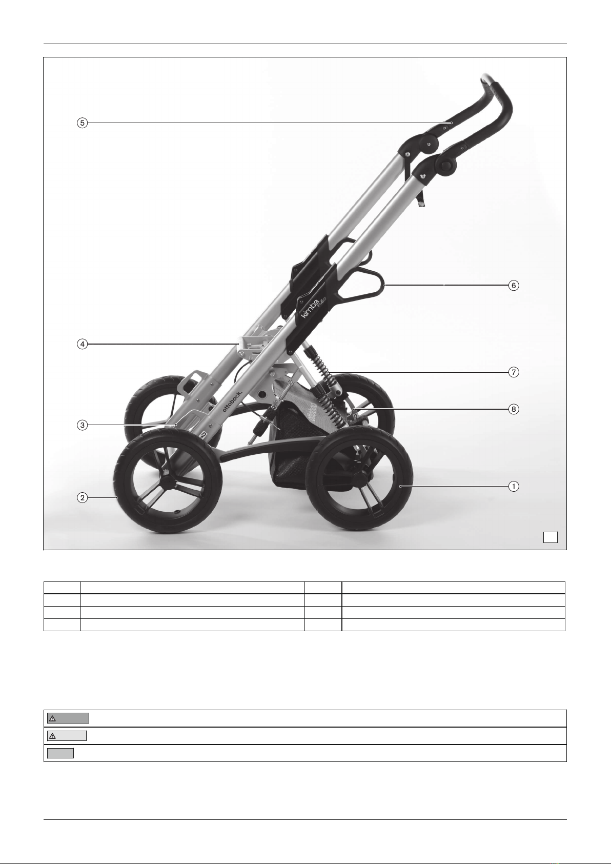
Product Overview1.3 5.................................................................................................................................
Safety2 7....................................................................................................................................................................
Explanation of Warning Symbols2.1 7.............................................................................................................
General Safety Instructions2.2 8....................................................................................................................
Service Work3 8.......................................................................................................................................................
General Information3.1 8..............................................................................................................................
Instructions for Adjustment3.2 8.....................................................................................................................
Maintenance Schedule3.3 9..........................................................................................................................
Required Tools and Accessories3.4 9.............................................................................................................
Outdoor Mobility Base3.5 9...........................................................................................................................
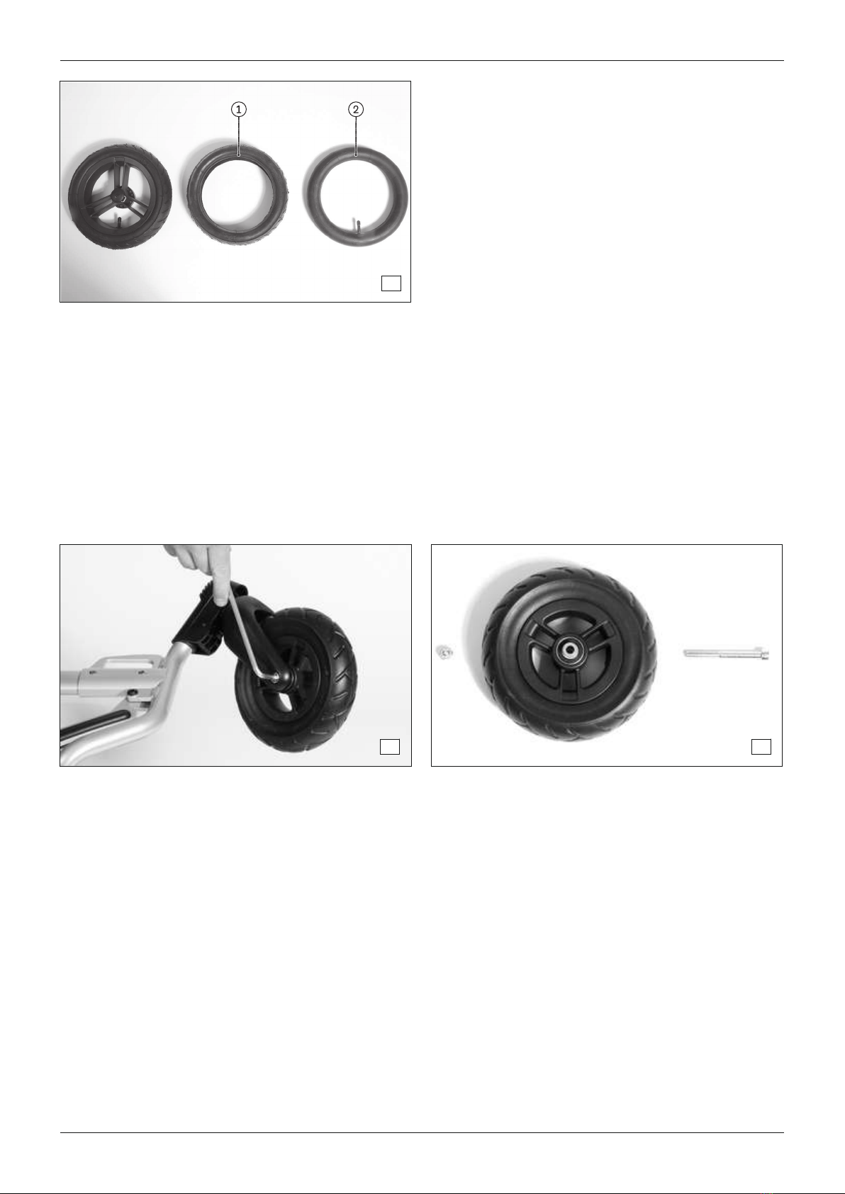
Rear Wheels3.5.1 9........................................................................................................................................
Replacing the Rear Wheel3.5.1.1 9.....................................................................................................................
Replacing the Casing3.5.1.2 9............................................................................................................................
Replacing the Tube (Pneumatic Tyre)3.5.1.3 9......................................................................................................
Front Wheels3.5.2 10......................................................................................................................................
Replacing a "Fixed" Front Wheel3.5.2.1 10..........................................................................................................
Replacing a "Swivelling" Front Wheel3.5.2.2 10...................................................................................................
Replacing the Caster Fork3.5.2.3 10...................................................................................................................
Replacing the Swivel Lock3.5.2.4 11...................................................................................................................
Replacing the Casing3.5.2.5 11..........................................................................................................................
Replacing the Tube (Pneumatic Tyre)3.5.2.6 12....................................................................................................
Seat Adapter3.5.3 12......................................................................................................................................
Replacing the Seat Adjustment Mechanism (Porter Cylinder)3.5.3.1 12...................................................................
Replacing the Seat Adapter (Tilt Activation on Standard Seat)3.5.3.2 13..................................................................
Suspension/Rear Wheel Linkage3.5.4 14..........................................................................................................
Replacing the Suspension3.5.4.1 14....................................................................................................................
Adjusting the suspension3.5.4.2 14.....................................................................................................................
Replacing the Complete Rear Wheel Linkage (incl. Wheel Lock)3.5.4.3 15..............................................................
Replacing the Rear Wheel Linkage (Individual)3.5.4.4 15.......................................................................................
Frame3.5.5 16................................................................................................................................................
Replacing the Front Frame3.5.5.1 16...................................................................................................................
Replacing the Upper Front Frame3.5.5.2 17.........................................................................................................
Replacing the Front Frame (Complete)3.5.5.3 18..................................................................................................
Replacing the Folding Tube3.5.5.4 18..................................................................................................................
Replacing the Fixed Tube Head3.5.5.5 19............................................................................................................
Push Bar3.5.6 20............................................................................................................................................
Replacing the Ratchet Joints with Folding Fixture3.5.6.1 20....................................................................................
Replacing the Push Bar3.5.6.2 20.......................................................................................................................
Options/Accessories3.5.7 20...........................................................................................................................
Replacing the Storage Basket3.5.7.1 20..............................................................................................................
Replacing/Retrofitting the Tip-Assist3.5.7.2 21......................................................................................................
Retrofitting the Respirator Platform3.5.7.3 21........................................................................................................
Multifunctional Seating Unit (Standard Seat)3.6 23..........................................................................................
Pads/Covers3.6.1 23......................................................................................................................................
Replacing the Seat Pad3.6.1.1 23.......................................................................................................................
Replacing the Backrest Pad3.6.1.2 24.................................................................................................................
Replacing the Covers3.6.1.3 24..........................................................................................................................
Replacing the Grab Rail Cover (Option)3.6.1.4 25.................................................................................................
Replacing the Frame Padding (Option)3.6.1.5 25..................................................................................................
Table of contents
2 | Ottobock
Table of contents
Kimba neo

Back3.6.2 26..................................................................................................................................................
Replacing the Back Insert3.6.2.1 26....................................................................................................................
Replacing the Knob3.6.2.2 27.............................................................................................................................
Removing/Installing the Tilt Activation Mechanism3.6.2.3 28...................................................................................
Replacing the Back Frame (Complete)3.6.2.4 29..................................................................................................
Replacing the Lateral Supports3.6.2.5 30.............................................................................................................
Replacing the Headrest Supports3.6.2.6 30.........................................................................................................
Installing/removing the seat depth reducer3.6.2.7 30.............................................................................................
Footplate/Knee Angle Assembly3.6.3 31...........................................................................................................
Replacing the Foot Plate3.6.3.1 31......................................................................................................................
Replacing Small Parts on the Footplate3.6.3.2 31.................................................................................................
Replacing the Knee Angle Assembly (Complete)3.6.3.3 32.....................................................................................
Replacing the Footplate Adapter3.6.3.4 32...........................................................................................................
Replacing the "Seat Adjuster"3.6.3.5 33..............................................................................................................
Base Frame (Seat Frame)3.6.4 33....................................................................................................................
Replacing the Base Frame (Tilt Activation Mechanism on Seat)3.6.4.1 33................................................................
Supports3.6.5 34............................................................................................................................................
Replacing the Headrest Supports3.6.5.1 34.........................................................................................................
Replacing the Thoracic Supports3.6.5.2 35..........................................................................................................
Replacing the Hip Supports3.6.5.3 35.................................................................................................................
Replacing the Lateral Supports3.6.5.4 36.............................................................................................................
Options/Accessories3.6.6 37...........................................................................................................................
Replacing/Retrofitting Safety Belts and Positioning Systems3.6.6.1 37....................................................................
Replacing/Retrofitting other Options3.6.6.2 38......................................................................................................
Appendices4 39........................................................................................................................................................
Technical Data4.1 39....................................................................................................................................
Maintenance Schedule4.2 40........................................................................................................................
Maintenance Schedule – Outdoor Mobility Base4.2.1 40.....................................................................................
Seating Unit Maintenance Schedule4.2.2 41......................................................................................................
Ottobock | 3Kimba neo
Table of contents

1 Introduction
1.1 Foreword
Regular maintenance is important – it improves safety and increases the lifespan of the product.
All Mobility products should be inspected and serviced once a year.
However, we recommend inspecting, readjusting, and if necessary servicing the product every 6 months if the
product is used frequently, by growing children or by users with changing clinical conditions.
Only use original spare parts for all service and maintenance work. The service and maintenance tasks described
here should only be completed by trained, qualified personnel and not by the user of the device.
This service and maintenance manual refers to the respective spare parts catalogues and the instructions for use of
the described products. Please use these documents together.
Use the maintenance schedule (checklist) as a template for making copies. Retain completed maintenance sched
ules and provide the customer with a copy.
Instructions for Use (Qualified Per
sonnel)
Instructions for Use (User)
Kimba neo 647G771=* 647G770=*
1.2 Support
Your national Ottobock team will be happy to answer any technical questions. The contact addresses and tele
phone numbers can be found on the back inside cover of the service manual.
4 | Ottobock Kimba neo
Introduction

1.3 Product Overview
1
Kimba Neo – outdoor mobility base with multifunctional seating unit and "swiveling" front wheels option
1 Plug-on rear wheel 6 Angle-adjustable backrest
2 "Swiveling" front wheel (option) 7 Adjustable push bar
3 Front lashing ring 8 Release handle, folding mechanism
4 Adjustable footrest 9 Rear lashing ring
5 Removable seat with lateral supports 10 Suspension
Ottobock | 5Kimba neo
Introduction

2
Kimba neo – outdoor mobility base with multifunctional seating unit and "swiveling" front wheels option
1 Plug-on rear wheel 6 Adjustable push bar
2 "Swiveling" front wheel (option) 7 Release handle, folding mechanism
3 Swivel lock 8 Separate seat tilt feature on frame
4 Front lashing ring 9 Rear lashing ring
5 Seat adapter 10 Suspension
6 | Ottobock
Introduction
Kimba neo

3
Kimba neo – outdoor mobility base with "fixed" front wheels
1 Plug-on rear wheel 5 Adjustable push bar
2 Plug-on "fixed" front wheel 6 Release handle, folding mechanism
3 Front lashing ring 7 Suspension
4 Seat adapter 8 Rear lashing ring
2 Safety
2.1 Explanation of Warning Symbols
WARNING Warnings regarding possible risks of severe accident or injury.
CAUTION Warnings regarding possible risks of accident or injury.
NOTICE Warnings regarding possible technical damage.
Ottobock | 7Kimba neo
Safety

2.2 General Safety Instructions
CAUTION
Failure to observe installation instructions
Pinching, crushing due to installation errors
►Do not reach between force-actuated surfaces during installation work.
CAUTION
Use of unsuitable tools
Pinching, crushing or damaging the product
►When working, use only tools that are suitable for the conditions at the workplace and whose proper use
ensures safety and health protection.
CAUTION
Re-use of self-locking nuts
Unintended loosening of the screw connections
►Always replace self-locking nuts with new self-locking nuts after disassembly.
NOTICE
Tipping or falling of the product
Damage to the product
►When you work on the product, secure it so that it cannot tip over or fall over.
►Use a clamping device to secure the product for all work at a workbench.
3 Service Work
3.1 General Information
INFORMATION
Read the service manual before starting work. Familiarise yourself with the functions of the product prior to
inspection and use. In order to do so, you can request this service manual and other documentation from the
manufacturer (see the overview of national Ottobock branches on the inside of the back cover) or download from
our homepage www.ottobock.de or www.ottobock.com.
INFORMATION
Clean and disinfect the product before commencing service work.
Observe all care instructions and product-specific inspection instructions in the instructions for use.
INFORMATION
Many screw connections utilise screws and nuts equipped with thread lock. If you loosen screw connections, be
sure to replace the respective nut or screw with one equipped with a new thread lock. If new screws or nuts with
thread lock are not available, apply a medium-strength liquid thread locking compound (such as Loctite® 241 or
Euro Lock A24.20) to the existing screws.
3.2 Instructions for Adjustment
WARNING
Failure to verify tipping resistance
Risk of the user falling or tipping over
►Changing the settings can lead to instability of the system as a whole. Verify tipping resistance after any
changes to the settings.
The sections that follow describe the replacement and retrofitting of standard and option parts on the product
shown on the cover.
8 | Ottobock
Service Work
Kimba neo

All instructions concerning the adjustment of the parts installed are included in the Instructions for Use (qualified
personnel) – see the section "Foreword" for the order number.
3.3 Maintenance Schedule
Maintenance schedule as a template for copying: see Page40.
3.4 Required Tools and Accessories
The following tools are required in order to perform the service work:
• Reversible ratchet handle wrench and sockets (size: 8–24)
• Torque wrench (measurement range 5-50 Nm)
• Wrench (size: 8–24)1)
• Allen wrench (size: 2.5–6)2)
• Screwdriver (blade width: 2.5/3.5/5 mm)
• Phillips head screwdriver (size: 2)
• Hammer (approx. 300 g); soft-faced hammer
• Pliers: cutting pliers, combination pliers, snap ring pliers
• Rivet gun (for rivets up to ø 5mm)
• Pin punch, ø 3/4/5/6 mm
• Drill/twist drill ø 3.2/5/5.2/6 mm
• Stanley knife with sickle hooked blade and standard blade
• Tyre mounting levers and inner tube repair kit*
• Workbench and vice with plastic jaws and rubber insert
• Measurement equipment: rule, spirit level
• Liquid thread locker, "medium" and "strong"
1) Included in 481C08=ST010 Tool Set
2) Size 3 – 6 contained in the 481C08=ST010 Tool Set
3.5 Outdoor Mobility Base
3.5.1 Rear Wheels
3.5.1.1 Replacing the Rear Wheel
1) Release the wheel lock.
2) Press down the lock on the rear wheels (see Fig.4).
3) Replace and reinstall the wheel. The locking mechanism must engage audibly.
4 5
3.5.1.2 Replacing the Casing
Replacing the casing on the rear wheel (see Fig.6, Pos.1) corresponds to replacing the casing on the caster
wheel: see Page11.
3.5.1.3 Replacing the Tube (Pneumatic Tyre)
Replacing the tube on the rear wheel (see Fig.6, Pos.2) corresponds to replacing the tube on the caster wheel:
see Page12.
Ottobock | 9Kimba neo
Service Work

6
3.5.2 Front Wheels
3.5.2.1 Replacing a "Fixed" Front Wheel
1) After pushing down the locking mechanism, pull the front wheel off to the outside and replace it (not illus
trated).
2) Slide on the front wheel. The locking mechanism must engage audibly.
3.5.2.2 Replacing a "Swivelling" Front Wheel
1) Put the frame on its side.
2) Remove the caster wheel axle in the caster fork (see Fig.7).
3) Remove and replace the caster wheel (see Fig.8).
4) Tighten the caster wheel axle to a torque of 9 Nm.
7 8
3.5.2.3 Replacing the Caster Fork
1) Remove the caster wheel (see the preceding section).
2) Loosen the caster fork mounting screw (see Fig.9).
3) Remove and replace the caster fork (see Fig.10).
4) Install the caster fork with the supplied mounting materials.
5) Tighten the caster fork to a torque of 25 Nm.
10 | Ottobock
Service Work
Kimba neo

9 10
3.5.2.4 Replacing the Swivel Lock
1) Remove the caster wheel and caster fork (see the preceding sections; see Fig.11).
2) Slide the swivel lock off the front frame and replace it (see Fig.12).
3) Slide the swivel lock onto the front frame.
4) Install the caster fork and caster wheel (see the preceding section).
11 12
3.5.2.5 Replacing the Casing
1) Remove the wheel (see Page10) and let out the air if required.
2) Using a tyre lever, remove the casing from the rim (see Fig.13).
3) Remove the tube.
4) Replace the casing (see Fig.14, Pos.1).
5) Fill the inner tube with a small amount of air before mounting in order to avoid damage and pinching.
6) Install the casing on the rim with a tyre lever.
7) Reinstall the wheel (see Page10).
13 14
Ottobock | 11Kimba neo
Service Work

3.5.2.6 Replacing the Tube (Pneumatic Tyre)
1) Remove the wheel (see Page10) and let out the air if required.
2) Using a tyre lever, remove the casing from the rim (see Page11).
3) Replace or repair the tube (see Fig.14, Pos.2; see Fig.15).
4) Fill the inner tube with a small amount of air before mounting in order to avoid damage and pinching.
5) Install the casing on the rim with a tyre lever.
6) Reinstall the wheel (see Page10).
15
3.5.3 Seat Adapter
3.5.3.1 Replacing the Seat Adjustment Mechanism (Porter Cylinder)
1) Remove the Bowden cable from the porter cylinder:
→Cut off the cable end sleeve (see Fig.16, Pos.1).
→Loosen the screw die.
→Remove the spring and Bowden cable guide (see Fig.16, Pos.2/3).
→Unthread the Bowden cable on the Porter cylinder.
2) Unlock and remove the spring folding bolt on the Porter cylinder (see Fig.17, Pos.1).
3) Remove the retaining ring (see Fig.17, Pos2) and the bearing journal.
4) Remove and replace the Porter cylinder.
5) Install the Porter cylinder with the mounting materials provided (see Fig.18). Note the following:
→Apply oil/grease to the bearing journal prior to installation (see Fig.18, Pos1).
→The piston rod of the Porter cylinder must not be lubricated (see Fig.18, Pos2).
→Note the Bowden cable guide between the seat adjustment mechanism and the Porter cylinder (see
Fig.19, Pos.1).
6) Conduct a functional test. Pay particular attention to the functionality of the seat tilt feature and the seat tilt
mechanism in the tilted position.
16 17
12 | Ottobock
Service Work
Kimba neo

18 19
3.5.3.2 Replacing the Seat Adapter (Tilt Activation on Standard Seat)
INFORMATION
When replacing the seat adapter, the Bowden cable also has to be replaced. It is included with the mounting
materials provided with the seat adapter (see Fig.23).
1) Remove the Bowden cable on the Porter cylinder (see Page12).
2) Unlock and remove the spring folding bolt on the porter cylinder (see Page12).
3) Remove the Bowden cable on the seat adapter (see Fig.20, Pos.1).
4) Loosen the mounting screw on one side of the seat adapter (see Fig.21, Pos.1).
5) Remove the screw; insert a mounting aid (M8 screw with counter nut) in place of the screw that was removed
and install the counter nut (see Fig.22, Pos.1).
6) Loosen the mounting screw on the other side.
7) Remove the disassembly aid.
8) Remove and replace the seat adapter.
9) Install the seat adapter with the mounting materials provided (see Fig.23). Tighten the seat adapter mounting
screws to a torque of 20 Nm:
10) Conduct a functional test. Pay particular attention to the functionality of the seat tilt feature and the seat tilt
mechanism in the tilted position.
20 21
Ottobock | 13Kimba neo
Service Work

22 23
3.5.4 Suspension/Rear Wheel Linkage
3.5.4.1 Replacing the Suspension
1) Remove the plug-on rear wheel.
2) Put the frame on its side.
3) Loosen the suspension mounting screws (see Fig.24, Pos. 1).
4) Remove and replace the suspension.
5) Install the suspension with the mounting materials provided (see Fig.25). Tighten the mounting screws.
6) To adjust the spring force, see the following section.
24 25
3.5.4.2 Adjusting the suspension
The suspension can be adjusted continuously according to the user's weight and the conditions of the road/sur
face:
1) Twist the adjustment rings on both sides of the frame equally (see Fig.26, item1).
→Clockwise: the suspension becomes tighter.
→Counterclockwise: the suspension becomes softer.
2) Check that the adjustment rings are positioned the same on both sides. The 4 marks can be used for orienta
tion (see Fig.26, item2; see Fig.27, item1).
14 | Ottobock
Service Work
Kimba neo

26 27
We recommend the following setting for the spring tension:
User weight Marking*
up to 10 kg up to 1st marking from the top
up to 20 kg up to 2nd marking from the top
up to 30 kg up to 3rd marking from the top
up to 40 kg up to 4th marking from the top
* Reference point: upper edge of the plastic adjustment nut
3.5.4.3 Replacing the Complete Rear Wheel Linkage (incl. Wheel Lock)
1) Remove the plug-on rear wheel.
2) Put the frame on its side.
3) Loosen the mounting screws between the rear wheel linkage and suspension (see Fig.28, Pos.1).
4) Loosen the mounting screws between the rear wheel linkage and lower front frame (see Fig.28, Pos.2).
5) Remove and replace the assembly "rear wheel linkage with wheel lock" (see Fig.29).
6) Install the complete rear wheel linkage using the mounting materials provided (see Fig.29). Tighten the mount
ing screws.
28 29
3.5.4.4 Replacing the Rear Wheel Linkage (Individual)
1) Remove the plug-on rear wheel.
2) Put the frame on its side.
3) Loosen the mounting screw between the rear wheel linkage and suspension (see Fig.30, Pos.1).
4) Loosen the mounting screw between the rear wheel linkage and lower front frame (see Fig.30, Pos.2).
5) Loosen the mounting screw on the axle stub (see Fig.30, Pos.3).
6) Disengage and replace the rear wheel linkage (see Fig.31, Pos.1). Ensure that the spring and lock bush of
the wheel lock are not ejected (see Fig.31, Pos.2).
7) Install the new rear wheel linkage with the mounting materials provided (see Fig.32). Ensure that the bore hole
of the axle stub (see Fig.31, Pos.3) fits flush with the mounting bore of the rear wheel linkage (see Fig.31,
Pos.4).
8) Tighten the mounting screws: see Fig.30, Pos.1 – 3.
Ottobock | 15Kimba neo
Service Work

30 31
32
3.5.5 Frame
3.5.5.1 Replacing the Front Frame
1) Remove the plug-on rear wheel.
2) Put the frame on its side.
3) Remove the caster wheels ("swivelling" front wheels: see Fig.33; item1; "fixed" front wheels: see Fig.35).
4) Loosen the mounting screws between the rear wheel linkages and lower front frame (see Fig.33, item2; see
Fig.35, item2).
5) Using a spiral bit (Ø5mm), bore out 8 rivets between the lower/upper front frame (see Fig.33, item3; see
Fig.35, item3). Tap out the rivets with a pin punch (Ø3mm).
6) Remove and replace the front frame.
→Front frame for swivelling front wheels (see Fig.34)
→Front frame for fixed front wheels (see Fig.36)
7) Rivet/install the front frame with the mounting materials provided.
8) Tighten the mounting screws between the rear wheel linkages and lower front frame (see Fig.33, item2; see
Fig.35, item2).
9) Install the caster wheels (see Page10 ff.).
16 | Ottobock
Service Work
Kimba neo

33 34
35 36
3.5.5.2 Replacing the Upper Front Frame
INFORMATION
The front frame is offered complete (see Fig.37) and alternatively in a version without seat adapter.
1) Remove the plug-on rear wheel.
2) Put the frame on its side.
3) Remove the caster wheels ("swivelling" front wheels: see Fig.39; item1; "fixed" front wheels: not illustrated).
4) Loosen the mounting screws on the suspension (see Fig.24, item1).
5) Only for front frame with seat adapter (see Page13):
→Remove the Bowden cable from the seat adapter (see Fig.20).
→Unlock and remove the spring folding bolt on the Porter cylinder (see Fig.17, item1).
6) Loosen the mounting screws between the folding tubes and fixed tube heads (see Fig.38, item1) and remove
the unit consisting of the folding tubes and push bar.
7) Using a spiral bit (Ø5mm), bore out 8 rivets between the lower/upper front frame (see Fig.33, item3) and tap
them out with a pin punch (Ø3mm).
8) Remove and replace the upper front frame (see Fig.37).
9) Install/rivet the front frame.
10) Tighten the mounting screws.
→see Fig.38, item1
→see Fig.24, item1
11) Only for front frame with seat adapter: Reconnect the seat adapter-Bowden cable and the seat adapter-
Porter cylinder (see Page13).
12) Install the caster wheels (see Page10 ff.).
Ottobock | 17Kimba neo
Service Work

37 38
3.5.5.3 Replacing the Front Frame (Complete)
1) Remove the plug-on rear wheel.
2) Put the frame on its side.
3) Remove the caster wheels ("swivelling" front wheels: see Fig.39; item1; "fixed" front wheels: not illustrated).
4) Loosen the mounting screws between the rear wheel linkages and lower front frame (see Fig.39, item2).
5) Loosen the mounting screws on the suspension (see Fig.39, item3).
6) Disconnect the front frame from the seat adjustment mechanism (see Page13):
→Remove the Bowden cable from the seat adapter (see Fig.20).
→Unlock and remove the spring folding bolt on the Porter cylinder (see Fig.17, item1).
7) Loosen the mounting screws between the folding tubes and fixed tube heads (see Fig.38, item1) and remove
the unit consisting of the folding tubes and push bar.
8) Remove and replace the front frame (see Fig.40).
9) Install the front frame with the mounting materials provided.
10) Tighten the mounting screws.
→see Fig.38, item1
→see Fig.39, item2/3
11) Reconnect the seat adapter-Bowden cable and the seat adapter-Porter cylinder (see Page13).
12) Install the caster wheels (see Page10 ff.).
39 40
3.5.5.4 Replacing the Folding Tube
1) Bore out the rivet between the folding tube and ratchet joint (see Fig.41, Pos.1) and remove the ratchet joint.
2) Loosen the mounting screws on the suspension (see Fig.41, Pos.2).
3) Loosen the mounting screws between the folding tube and fixed tube head (see Fig.41, Pos.3).
4) Replace the folding tube.
5) Install the folding tube with the mounting materials provided (see Fig.42). Tighten the mounting screws: see
Fig.41, Pos.2/3.
6) Rivet the ratchet joint to the folding tube (see Fig.41, Pos.1).
7) Attach the sticker to the folding tube.
18 | Ottobock
Service Work
Kimba neo

41 42
3.5.5.5 Replacing the Fixed Tube Head
1) Loosen the mounting screws on the suspension (see Fig.24, Pos.1).
2) Loosen the mounting screws between the folding tubes and fixed tube heads (see Fig.38, Pos.1) and remove
the unit consisting of the folding tubes and push bar.
3) Using a spiral bit (Ø5mm), bore out the rivet on the fixed tube head and tap it out with a pin punch (Ø3mm)
(see Fig.43).
4) Tap out the fixed tube head from the upper front frame and replace it (see Fig.44).
NOTICE! Damage to the fixed tube head. Only use the surface shown in the illustration for tapping the
component in or out.
5) Using a pin punch, press the fixed tube head into the upper front frame (see Fig.45).
6) Rivet the fixed tube head (see Fig.46).
7) Reinstall the folding tubes with push bar and the suspension.
8) Tighten the mounting screws.
→see Fig.38, Pos.1
→see Fig.24, Pos.1
43 44
45 46
Ottobock | 19Kimba neo
Service Work

3.5.6 Push Bar
3.5.6.1 Replacing the Ratchet Joints with Folding Fixture
1) Using a spiral bit (Ø5mm), bore out 4 rivets on each ratchet joint and tap them out with a pin punch (Ø3mm)
(see Fig.47, Pos.1/2).
2) Remove and replace the ratchet joints (see Fig.48).
3) Rivet the ratchet joint with the folding fixture on the correct side (see Fig.49).
47 48
49 50
3.5.6.2 Replacing the Push Bar
1) Using a spiral bit (Ø5mm), bore out 2 rivets on each ratchet joint and tap them out with a pin punch (Ø3mm)
(see Fig.47, Pos.1).
2) Remove and replace the push bar (see Fig.50).
3) Rivet the push bar onto the ratchet joint.
3.5.7 Options/Accessories
3.5.7.1 Replacing the Storage Basket
NOTICE
Incorrect attachment
Damage to the product
►During the attachment, make sure that the product cannot grind against the wheels.
1) Open the snap fasteners and hook-and-loop straps of the storage basket (see Fig.51, Pos. 1; see Fig.52,
Pos.1).
2) Remove and replace the storage basket.
3) Mount the storage basket, with the proper side, to the frame using the snap fasteners and hook-and-loop
straps (see Fig.51, Pos.1; see Fig.52, Pos.1).
20 | Ottobock
Service Work
Kimba neo
Other manuals for Kimba neo
8
This manual suits for next models
1
Table of contents