Otto Bock 17PA1 Series User manual

17PA1=*
Gebrauchsanweisung ................................................................ 4
Instructions for use .................................................................... 11
Instructions d'utilisation ............................................................. 18
Istruzioni per l’uso ..................................................................... 26
Instrucciones de uso ................................................................. 33
Manual de utilização .................................................................. 41
Gebruiksaanwijzing ................................................................... 49
Bruksanvisning ......................................................................... 56
Brugsanvisning ......................................................................... 63
Bruksanvisning ......................................................................... 70
Instrukcja użytkowania ............................................................... 77
Használati utasítás .................................................................... 85
Návod k použití ......................................................................... 92
Upute za uporabu ..................................................................... 100
Kullanma talimatı ....................................................................... 107
Руководство по применению .................................................... 114

1
2

17PA1=14*
30Y289
506G21=M6 14
2
17PA1=20*
506G21=M6 14
3
3

1 Vorwort Deutsch
INFORMATION
Datum der letzten Aktualisierung: 2022-02-03
►Lesen Sie dieses Dokument vor Gebrauch des Produkts aufmerksam
durch und beachten Sie die Sicherheitshinweise.
►Weisen Sie den Benutzer in den sicheren Gebrauch des Produkts ein.
►Wenden Sie sich an den Hersteller, wenn Sie Fragen zum Produkt ha
ben oder Probleme auftreten.
►Melden Sie jedes schwerwiegende Vorkommnis im Zusammenhang
mit dem Produkt, insbesondere eine Verschlechterung des Gesund
heitszustands, dem Hersteller und der zuständigen Behörde Ihres Lan
des.
►Bewahren Sie dieses Dokument auf.
Die Gebrauchsanweisung gibt Ihnen wichtige Informationen zur Verarbei
tung der Orthesenknöchelgelenke aus Kunststoff 17PA1=*.
2 Produktbeschreibung
2.1 Verfügbare Größen
Kennzeichen Größe Einsteckbereich in mm Material
17PA1* *=14 14
17PA1* *=20 20
Kunst
stoff
2.2 Bauteile/Konstruktion
Lieferumfang (siehe Abb.1)
ArtikelnummerPos. Menge
[Stück]
Bezeichnung
17PA1=14 17PA1=20
1 2 Gewindestift 506G21=M6
x14,
506G3=M6x
14
2 2 Zylinderstift 506A5=5xM
6x6
506A8=5x20
3 1 Gelenkschraube
4 1 Gelenkbolzen
5 1 Buchse
29PA1=14 29PA1
6 1 Knöchelgelenk
8 1 Gelenkmutter
9 1 Buchse
29PA1=14 29PA1
4

Lieferumfang (siehe Abb.1)
ArtikelnummerPos. Menge
[Stück]
Bezeichnung
17PA1=14 17PA1=20
10 1 Gewindestift 506G21=M4x12
11 1 Bohrung für Gewin
destift
12 1 Einsteckbereich für
Schiene
13 2 Kugel 509Y1=5.0
14 2 Zylinderstift 506A8=2x16 506A8=2.5x
18
15 2 Druckfeder 513D87=0.7
5x2.95x2
513D18=4.7
x31-1
16 2 Gewindestift 30Y289 506G3=M6x
14
17 2 Schraube 501S84=M4
x25
501T28=M6
x35
18 2 Adapter für Parallel
richtrohr
29PK4=14
19 1 Parallelrichtrohr 30Y216
Nicht im Lieferumfang enthalten (siehe Abb.1)
Pos. Menge
[Stück]
Bezeichnung Kennzeichen
7 1 Fußbügel 17PF1*
20 1 Schiene 651P4*, 605P8*
3 Bestimmungsgemäße Verwendung
3.1 Verwendungszweck
Die Orthesenknöchelgelenke sind ausschließlich paarweise zur ortheti
schen Versorgung der unteren Extremität bei einem Patienten einzusetzen.
Artikelnummer Max. Körpergewicht
17PA1=14 45kg
17PA1=20 100kg
3.2 Indikationen
Bei Teillähmung oder kompletter Lähmung der Beinmuskulatur.
Die Indikation wird vom Arzt gestellt.
5

3.3 Weitere Nutzungseinschränkungen
Das Produkt ist nicht für die Verwendung beim Sport geeignet.
3.4 Lebensdauer
Das Produkt ist bei bestimmungsgemäßer Verwendung und fachgerechter
Montage für eine Lebensdauer von 3Jahren ausgelegt.
3.5 Qualifikation
Die Versorgung eines Patienten mit dem Produkt darf nur von ausgebilde
tem Fachpersonal vorgenommen werden. Es wird vorausgesetzt, dass das
Fachpersonal im Umgang mit den unterschiedlichen Techniken, Materialien,
Werkzeugen und Maschinen vertraut ist.
3.6 Kombinationsmöglichkeiten
Die Orthesenknöchelgelenke 17PA1* können mit den Orthesenkniegelenken
17PK1* kombiniert werden.
4 Sicherheit
4.1 Bedeutung der Warnsymbolik
VORSICHT Warnung vor möglichen Unfall- und Verletzungsgefahren.
HINWEIS Warnung vor möglichen technischen Schäden.
4.2 Sicherheitshinweise
VORSICHT
Überbeanspruchung tragender Bauteile
Verletzungen durch Funktionsveränderung oder –verlust
►Verwenden Sie das Produkt nur für den definierten Einsatzbereich.
►Falls das Produkt extremen Belastungen ausgesetzt wurde (z.B. durch
Sturz), sorgen Sie für geeignete Maßnahmen (z.B. Reparatur, Aus
tausch, Kontrolle durch den Kundenservice des Herstellers, etc.).
VORSICHT
Fehlerhafter Aufbau oder Montage
Verletzungen durch Funktionsveränderung oder -verlust
►Die Montage darf nur von ausgebildetem Fachpersonal durchgeführt
werden.
►Beachten Sie die Aufbau- und Montagehinweise.
6

VORSICHT
Mechanische Beschädigung des Produkts
Verletzungen durch Funktionsveränderung oder –verlust
►Arbeiten Sie sorgfältig mit dem Produkt.
►Prüfen Sie das Produkt auf Funktion und Gebrauchsfähigkeit.
►Verwenden Sie das Produkt bei Funktionsveränderungen oder -verlust
nicht weiter und lassen Sie es durch autorisiertes Fachpersonal kon
trollieren.
VORSICHT
Überbeanspruchung durch Gebrauch an mehr als einem Patienten
Verletzungsgefahr und Funktionsverlust sowie Beschädigungen am Pro
dukt
►Verwenden Sie das Produkt nur an einem Patienten.
►Beachten Sie die Wartungsempfehlung.
VORSICHT
Unzulässige Verwendung von Schmiermitteln
Verletzungsgefahr und Funktionsverlust sowie Beschädigungen am Pro
dukt
►Das Produkt ist schmiermittelfrei konzipiert. Vermeiden Sie den Kon
takt mit Schmiermitteln (z.B. Fette, Öle).
►Reinigen Sie das Produkt oder Teile des Produkts nach Kontakt mit
Schmiermitteln umgehend mit einem entfettenden Reiniger (z.B. Ace
ton oder Isopropylalkohol).
HINWEIS
Kontakt mit Salzwasser, chlor-/seifenhaltigem Wasser, Süßwasser
sowie abrasiven Medien (z. B. Sand)
Beschädigungen und vorzeitiger Verschleiß am Produkt
►Reinigen Sie das Produkt umgehend nach jedem Kontakt mit den oben
genannten Stoffen gemäß dem Kapitel „Reinigung“.
HINWEIS
Produkt wird falschen Umgebungsbedingungen ausgesetzt
Beschädigungen, Versprödung oder Zerstörung durch unsachgemäße
Handhabung
7

►Vermeiden Sie die Lagerung bei kondensierender Umgebungsfeuch
tigkeit.
►Vermeiden Sie den Kontakt mit abrasiven Medien (z.B. Sand, Staub).
►Setzen Sie das Produkt keinen Temperaturen unter -10°C und über
+60°C aus (z.B. Sauna, übermäßiger Sonneneinstrahlung, Trocknen
auf der Heizung).
5 Gebrauchsfähigkeit herstellen
INFORMATION
►Achten Sie vor Abgabe der Orthese auf die parallele Ausrichtung der
Orthesengelenke.
INFORMATION
Um den parallelen Aufbau der Orthesengelenke zu ermöglichen, liegt je
dem Orthesengelenkpaar eine Justierhilfe bei. Die Justierhilfe besteht aus
2 Schrauben, 1 Parallelrichtrohr und je nach Größe der Orthesengelenke 2
Adapterstücken.
INFORMATION
Die Anleitung zur Herstellung einer Orthese mit Kunststoff Orthesengelen
ken ist in der Technischen Information 646T546 enthalten. Die hier be
schriebene Thermoplasttechnik ist eine Empfehlung von Ottobock und
muss an die Bedürfnisse des Patienten angepasst werden.
Fußbügel montieren
1) Die Lagerbuchsen auf das Orthesengelenk aufstecken.
2) Den Fußbügel mit dem Gelenkbolzen und der Gelenkmutter fixieren.
3) Die Gelenkmutter mit der Gelenkschraube verschrauben.
4) Die Gewinde der Schraubverbindungen mit einem entfettenden Reiniger
reinigen und mit Loctite 241 sichern.
Druckfeder montieren
>Voraussetzung: Der Fußbügel ist montiert.
1) Die Kugel, die Druckfeder und den Zylinderstift in den Einschraubkanal
einsetzen (siehe Abb.2, siehe Abb.3).
2) Den Gewindestift in den Einschraubkanal einschrauben und die Feder
kraft des Knöchelgelenks einstellen.
3) Die Gewinde der Schraubverbindungen mit einem entfettenden Reiniger
reinigen und mit Loctite 241 sichern.
8

Anschlagstift montieren
>Voraussetzung: Der Fußbügel ist montiert.
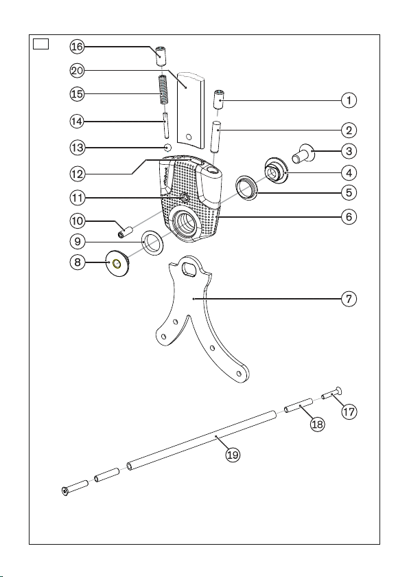
1) Den Anschlagstift in den Einschraubkanal einsetzen (siehe Abb.2, siehe
Abb.3).
2) Den Gewindestift in den Einschraubkanal einschrauben und die Winkel
stellung des Orthesengelenks einstellen.
3) Die Gewinde der Schraubverbindungen mit einem entfettenden Reiniger
reinigen und mit Loctite 241 sichern.
Schiene montieren
>Benötigte Werkzeuge: Bohrer 624S14=4, Senker 726S9=90x11.5.
1) Die Schiene in den Einsteckbereich des Orthesengelenks einlegen und
die Position des Bohrlochs markieren.
2) Die Bohrung mit dem Bohrer 624S14* einbringen.
3) Die Bohrung mit dem Senker 726S9* entgraten.
4) Die Schiene im Einsteckbereich mit dem Gewindestift 506G21* fixieren.
INFORMATION: Zur finalen Montage werden die Schienen im Ein
steckbereich eingeklebt.
Schienen einkleben
Benötigte Materialien: Spezialklebstoff 636W28*, entfettender Reiniger
Aus Stabilitätsgründen ist die Verklebung der Schienen in den Einsteckbe
reichen erforderlich.
1) Die Verbindungsflächen mit einem entfettenden Reiniger reinigen.
2) Den Spezialklebstoff auf die Verbindungsflächen auftragen.
3) Die Schienen einsetzen.
4) Mit den beiliegenden Schrauben fixieren.
5) Mindestens 4Stunden aushärten lassen.
INFORMATION: Die endgültige Festigkeit ist nach 16Stunden er
reicht.
Schiene demontieren
1) Den Gewindestift herausschrauben.
2) Die Schiene herausschlagen und entnehmen.
17PA1*
Durch die individuelle Kombination von Kugel, Anschlagstift und Druckfeder
mit den Gewindestiften werden die Orthesenknöchelgelenke 17PA1* an die
Bedürfnisse des Patienten angepasst.
6 Reinigung
Reinigen Sie das Produkt umgehend nach Kontakt mit:
9

• Salzwasser, Chlorwasser, Seifenwasser, Schweiß, Urin, Spritzwasser
(z.B. nach Regen) und Verschmutzungen.
1) Das Produkt mit reinem Süßwasser abspülen.
2) Das Produkt mit einem Tuch abtrocknen oder an der Luft trocknen las
sen. Direkte Hitzeeinwirkung vermeiden (z.B. Ofen- oder Heizkörperhit
ze).
Reinigen Sie das Produkt umgehend nach Kontakt mit:
• Schmiermittel (z.B. Öle und Fette)
1) Ein Tuch mit einem entfettenden Reiniger benetzen.
2) Die Orthesengelenke oder Komponenten mit dem Tuch abwischen.
7 Wartung
INFORMATION
Möglicherweise ist das Produkt patientenspezifisch einer erhöhten
Belastung ausgesetzt.
►Verkürzen Sie die Wartungsintervalle gemäß den zu erwartenden Be
lastungen.
Der Hersteller schreibt für das Produkt mindestens eine halbjährliche Funkti
ons- und Verschleißkontrolle vor.
Die Ersatzteile sind im Kapitel Produktbeschreibung unter „Bauteile/Kon
struktion“ aufgeführt.
Buchse austauschen
1) Die Gelenkschraube lösen und den Gelenkbolzen und die Gelenkmutter
aus dem Orthesengelenk entfernen.
2) Das Orthesengelenk demontieren.
3) Die ausgetauschte Buchse in das Orthesengelenk einsetzen.
4) Das Orthesengelenk mit dem Gelenkbolzen, der Gelenkmutter und der
Gelenkschraube montieren.
5) Die Gewinde der Schraubverbindungen mit einem entfettenden Reiniger
reinigen und mit Loctite 241 sichern.
8 Entsorgung
Das Produkt gemäß den geltenden nationalen Vorschriften entsorgen.
9 Rechtliche Hinweise
Alle rechtlichen Bedingungen unterliegen dem jeweiligen Landesrecht des
Verwenderlandes und können dementsprechend variieren.
10

9.1 Haftung
Der Hersteller haftet, wenn das Produkt gemäß den Beschreibungen und
Anweisungen in diesem Dokument verwendet wird. Für Schäden, die durch
Nichtbeachtung dieses Dokuments, insbesondere durch unsachgemäße
Verwendung oder unerlaubte Veränderung des Produkts verursacht werden,
haftet der Hersteller nicht.
9.2 CE-Konformität
Das Produkt erfüllt die Anforderungen der Verordnung (EU) 2017/745 über
Medizinprodukte. Die CE-Konformitätserklärung kann auf der Website des
Herstellers heruntergeladen werden.
1 Foreword English
INFORMATION
Date of last update: 2022-02-03
►Please read this document carefully before using the product and
observe the safety notices.
►Instruct the user in the safe use of the product.
►Please contact the manufacturer if you have questions about the
product or in case of problems.
►Report each serious incident related to the product to the manufacturer
and to the relevant authority in your country. This is particularly import
ant when there is a decline in the health state.
►Please keep this document for your records.
These instructions for use provide you with important information on the pro
cessing of the 17PA1=* orthotic ankle joints made of plastic.
2 Product description
2.1 Available sizes
Reference number Size Insertion zone in mm Material
17PA1* *=14 14
17PA1* *=20 20
Plastic
11

2.2 Components/design
Scope of delivery (see fig.1)
Article numberItem Quantity
[Piece
(s)]
Designation
17PA1=14 17PA1=20
1 2 Set screw 506G21=M6
x14,
506G3=M6x
14
2 2 Cylinder pin 506A5=5xM
6x6
506A8=5x20
3 1 Joint screw
4 1 Joint bolt
5 1 Bushing
29PA1=14 29PA1
6 1 Ankle joint
8 1 Joint nut
9 1 Bushing
29PA1=14 29PA1
10 1 Set screw 506G21=M4x12
11 1 Bore holefor set
screw
12 1 Insertion zone for bar
13 2 Ball 509Y1=5.0
14 2 Cylinder pin 506A8=2x16 506A8=2.5x
18
15 2 Compression spring 513D87=0.7
5x2.95x2
513D18=4.7
x31-1
16 2 Set screw 30Y289 506G3=M6x
14
17 2 Screw 501S84=M4
x25
501T28=M6
x35
18 2 Adapter for parallel
alignment tube
29PK4=14
19 1 Parallel alignment
tube
30Y216
12

Not included in the scope of delivery (see fig.1)
Item Quantity
[Piece
(s)]
Designation Reference number
7 1 Foot stirrup 17PF1*
20 1 Bar 651P4*, 605P8*
3 Intended use
3.1 Indications for use
The orthotic ankle joints are to be used exclusively in pairs to provide
orthotic treatment for a patient’s lower limbs.
Article number Max. body weight
17PA1=14 45kg
17PA1=20 100kg
3.2 Indications
Partial or total paralysis of the leg muscles.
Indications must be determined by the physician.
3.3 Further Usage Restrictions
The product is not suitable for use in sports.
3.4 Lifetime
The product is designed for a lifetime of 3years when used as intended and
assembled professionally.
3.5 Qualification
Patients may be fitted with the product only by trained qualified personnel.
The qualified personnel must be familiar with the handling of the various
techniques, materials, machines and tools.
3.6 Combination possibilities
The 17PA1* orthotic ankle joints can be combined with the 17PK1* orthotic
knee joints.
4 Safety
4.1 Explanation of warning symbols
CAUTION Warning regarding possible risks of accident or injury.
NOTICE Warning regarding possible technical damage.
13

4.2 Safety instructions
CAUTION
Excessive strain on load-bearing components
Injuries due to changes in or loss of functionality
►Only use the product for the defined area of application.
►If the product has been exposed to extreme strain (e.g.due to falling),
take any necessary measures (e.g.repair, replacement, inspection by
the manufacturer's customer service, etc.).
CAUTION
Incorrect alignment or assembly
Injuries due to changes in or loss of functionality
►The product may only be installed by trained, qualified personnel.
►Observe the alignment and assembly instructions.
CAUTION
Mechanical damage to the product
Injuries due to changes in or loss of functionality
►Use caution when working with the product.
►Check the product for proper function and readiness for use.
►In case of changes in or loss of functionality, discontinue use of the
product and have it checked by authorised, qualified personnel.
CAUTION
Excessive strain due to use on more than one patient
Risk of injury and loss of functionality as well as damage to the product
►Use the product on only one patient.
►Observe the maintenance recommendations.
CAUTION
Unallowable use of lubricants
Risk of injury and loss of functionality as well as damage to the product
►The product is designed to be free of lubricants. Avoid contact with
lubricants (e.g. grease, oil).
►After contact with lubricants, promptly clean the product or parts of the
product with a degreasing cleaning agent (e.g. acetone or isopropyl
alcohol).
14

NOTICE
Contact with saltwater or water containing chlorine/soap, fresh
water or abrasive substances (e.g. sand)
Damage and premature product wear
►Following any contact with the substances identified above, promptly
clean the product in accordance with the section "Cleaning".
NOTICE
Exposure of the product to unsuitable environmental conditions
Damage, brittleness or destruction due to improper handling
►Avoid storage in condensing ambient humidity.
►Avoid contact with abrasive substances (e.g.sand, dust).
►Do not expose the product to temperatures below -10°C (14°F) or
above +60°C (140°F) (e.g.sauna, excessive sunlight, drying on a
radiator).
5 Preparing the product for use
INFORMATION
►Check that the orthotic joints are aligned in the parallel position before
delivering the orthosis.
INFORMATION
An adjustment aid is included with each pair of orthotic joints so the orthot
ic joints can be aligned parallel to one another. The adjustment aid con
sists of two screws, one parallel alignment tube and, depending on the size
of the orthotic joints, two adapter pieces.
INFORMATION
The instructions for fabricating an orthosis with orthotic joints made of
plastic are included in the 646T546 technical information. The thermo
plastic technology described here is a recommendation from Ottobock and
must be adjusted to the needs of the patient.
15

Mounting the foot stirrup
1) Slide the bearing bushings onto the orthotic joint.
2) Secure the foot stirrup with the joint bolt and joint nut.
3) Screw the joint nut together with the joint screw.
4) Clean the threads of the screw connections using a degreasing cleaner
and secure them with Loctite 241.
Mounting the compression spring
>Prerequisite: The foot stirrup is mounted.
1) Insert the ball, compression spring and cylinder pin into the threaded
hole (see fig.2, see fig.3).
2) Screw the set screw into the threaded hole and set the spring force of
the ankle joint.
3) Clean the threads of the screw connections using a degreasing cleaner
and secure them with Loctite 241.
Mounting the stop pin
>Prerequisite: The foot stirrup is mounted.
1) Insert the stop pin into the threaded hole (see fig.2, see fig.3).
2) Screw the set screw into the threaded hole and set the angle of the
orthotic joint.
3) Clean the threads of the screw connections using a degreasing cleaner
and secure them with Loctite 241.
Mounting the bar
>Required tools: 624S14=4 drill bit, 726S9=90x11.5 counterbore.
1) Insert the bar into the insertion zone of the orthotic joint and mark the
position of the bore hole.
2) Use the 624S14* drill bit to make the bore hole.
3) Deburr the bore with the 726S9* counterbore.
4) Secure the bar in the insertion zone with the 506G21* set screw.
INFORMATION: The bars are glued in the insertion zone to com
plete the assembly.
Gluing in bars
Required materials: 636W28* special adhesive, degreasing cleaner
The bars must be glued in the insertion zones to ensure stability.
1) Clean the connecting surfaces with a degreasing cleaner.
2) Apply the special adhesive to the connecting surfaces.
3) Insert the bars.
4) Secure with the enclosed screws.
16

5) Allow to cure for at least 4hours.
INFORMATION: Final bonding strength will be reached after
16hours.
Removing the bar
1) Unscrew the set screw.
2) Tap out and remove the bar.
17PA1*
The 17PA1* orthotic ankle joints are adapted to the needs of the patient
through the individual combination of the ball, stop pin and compression
spring with the set screws.
6 Cleaning
Promptly clean the product after contact with:
• Water containing salt, chlorine or soap, perspiration, urine or splashed
water (e.g.after rain) and soiling.
1) Rinse the product with clear fresh water.
2) Dry the product with a cloth or allow it to air dry. Avoid exposure to direct
heat (e.g.from an oven or radiator).
Clean the product immediately after contact with:
• Lubricants (e.g.oil and grease)
1) Wet a cloth with a degreasing cleaner.
2) Wipe the orthotic joints or components with the cloth.
7 Maintenance
INFORMATION
The product may be exposed to increased loads by the patient.
►Shorten the maintenance intervals according to the expected loads.
The manufacturer requires at least a semi-annual inspection of the product
to verify functionality and check for wear.
Spare parts are listed in the section "Components/design".
Replacing the bushing
1) Loosen the joint screw and remove the joint bolt and joint nut from the
orthotic joint.
2) Disassemble the orthotic joint.
3) Insert the new bushing into the orthotic joint.
4) Assemble the orthotic joint with the joint bolt, joint nut and joint screw.
17

5) Clean the threads of the screw connections using a degreasing cleaner
and secure them with Loctite 241.
8 Disposal
Dispose of the product in accordance with national regulations.
9 Legal information
All legal conditions are subject to the respective national laws of the country
of use and may vary accordingly.
9.1 Liability
The manufacturer will only assume liability if the product is used in accord
ance with the descriptions and instructions provided in this document. The
manufacturer will not assume liability for damage caused by disregarding the
information in this document, particularly due to improper use or unauthor
ised modification of the product.
9.2 CE conformity
The product meets the requirements of Regulation (EU) 2017/745 on medic
al devices. The CE declaration of conformity can be downloaded from the
manufacturer's website.
1 Avant-propos Français
INFORMATION
Date de la dernière mise à jour: 2022-02-03
►Veuillez lire attentivement l’intégralité de ce document avant d’utiliser le
produit ainsi que respecter les consignes de sécurité.
►Apprenez à l’utilisateur comment utiliser son produit en toute sécurité.
►Adressez-vous au fabricant si vous avez des questions concernant le
produit ou en cas de problèmes.
►Signalez tout incident grave survenu en rapport avec le produit, notam
ment une aggravation de l’état de santé, au fabricant et à l’autorité
compétente de votre pays.
►Conservez ce document.
La notice d’utilisation fournit des informations importantes sur la confection
des articulations de cheville pour orthèse en plastique 17PA1=*.
18

2 Description du produit
2.1 Tailles disponibles
Référence Taille Zone d’emboîtement
en mm
Matériau
17PA1* *=14 14
17PA1* *=20 20
Matière
plastique
2.2 Construction / éléments constitutifs
Contenu de la livraison (voir ill.1)
Référence de l’articlePos. Quantité
[unité]
Désignation
17PA1=14 17PA1=20
1 2 Vis sans tête 506G21=M6
x14,
506G3=M6x
14
2 2 Goupille cylindrique 506A5=5xM
6x6
506A8=5x20
3 1 Vis d’articulation
4 1 Boulon d’articulation
5 1 Douille
29PA1=14 29PA1
6 1 Articulation de che
ville
8 1 Écrou d’articulation
9 1 Douille
29PA1=14 29PA1
10 1 Vis sans tête 506G21=M4x12
11 1 Trou pour vis sans
tête
12 1 Zone d’emboîtement
pour ferrure
13 2 Bille 509Y1=5.0
14 2 Goupille cylindrique 506A8=2x16 506A8=2.5x
18
15 2 Ressort de compres
sion
513D87=0.7
5x2.95x2
513D18=4.7
x31-1
16 2 Vis sans tête 30Y289 506G3=M6x
14
17 2 Vis 501S84=M4
x25
501T28=M6
x35
19

Contenu de la livraison (voir ill.1)
Référence de l’articlePos. Quantité
[unité]
Désignation
17PA1=14 17PA1=20
18 2 Adaptateur pour
tube de dressage
parallèle
29PK4=14
19 1 Tube de dressage
parallèle
30Y216
Composants non compris dans la livraison (voir ill.1)
Pos. Quantité
[unité]
Désignation Référence
7 1 Étrier de pied 17PF1*
20 1 Ferrure 651P4*, 605P8*
3 Utilisation conforme
3.1 Usage prévu
Les articulations de cheville pour orthèse doivent être utilisées exclusive
ment par paire pour l’appareillage orthétique du membre inférieur d’un pa
tient.
Référence de l’article Poids max. de l’utilisateur
17PA1=14 45kg
17PA1=20 100kg
3.2 Indications
En cas de paralysie partielle ou complète des muscles des jambes.
L’indication est déterminée par le médecin.
3.3 Autres restrictions d'utilisation
Le produit n’est pas adapté pour pratiquer des activités sportives.
3.4 Durée de vie
Le produit est conçu pour une durée de vie de 3ans si son utilisation est
conforme et le montage correct.
3.5 Qualification
Seul un personnel spécialisé dûment formé est autorisé à appareiller un pa
tient avec le produit. Il est entendu que ces professionnels sont familiarisés
à l’utilisation des diverses méthodes et différents matériaux, outils et ma
chines requis.
20
Table of contents
Languages:
Other Otto Bock Safety Equipment manuals
Popular Safety Equipment manuals by other brands

MSA
MSA Vautex Elite ET quick start guide

Montanari
Montanari PD50 Installation, use and maintenance

Lanex
Lanex LX2 quick start guide

Summit Treestands
Summit Treestands Seat-O-The Pants Series instructions

Radal Technology
Radal Technology SPK-POD-A user guide

SKYLOTEC
SKYLOTEC MOBILFIX Assembly and operating instructions