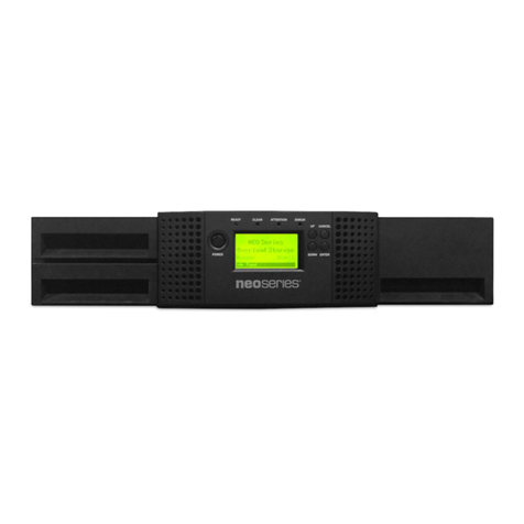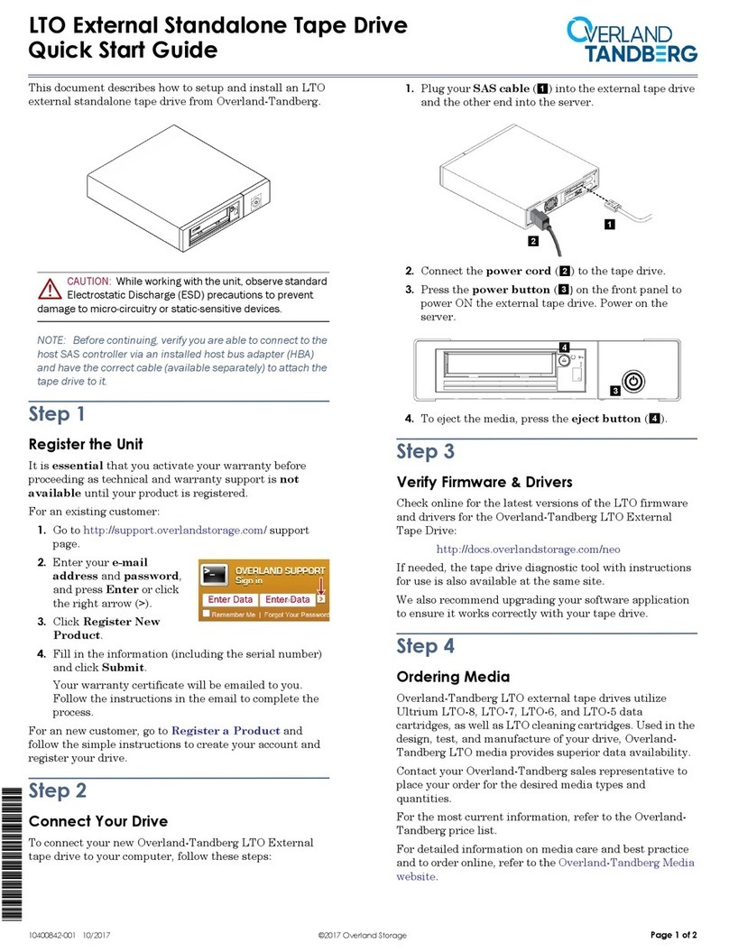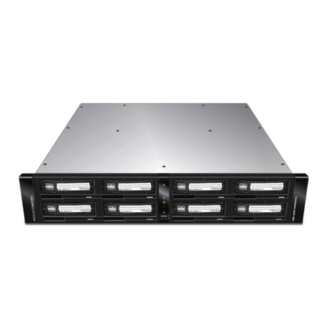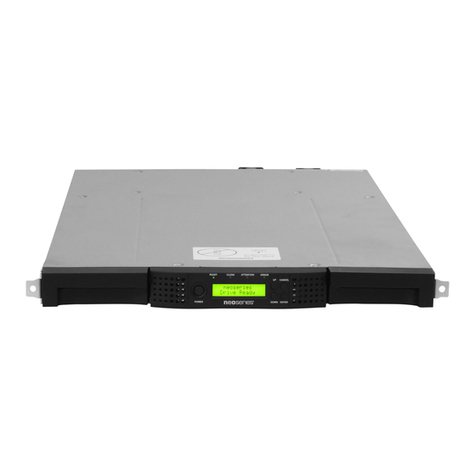
NEOxl 40 3U Tape Library Base Module Quick Start Guide
10400895 ©2019 Overland-Tandberg Page 3 of 5
Step 4
WARNING: To reduce the risk of electric shock or
damage to equipment, always remove any power cords
while working with the unit.
WARNUNG: Um das Risiko eines elektrischen Schlags
oder Schäden am Gerät zu vermeiden, ziehen Sie stets
den Netzstecker, bevor Sie an der Einheit arbeiten.
AVERTISSEMENT: Pour réduire le risque de choc
électrique ou endommagement de l'équipement, retirez
toujours les cordons électriques en travaillant avec
l'appareil.
The NEOxl 40 3U tape libraries are expandable and accept
add-on components to enhance performance:
•The Base Module comes without tape drives. Tape
drives are always installed in the module from the
bottom up.
•A second Power Supply Unit can be added to Base
Module for redundancy.
•Expansion Modules can be added to the library stack of
modules and should be installed in the rack with the
Base Module before cabling.
IMPORTANT: Follow the component instructions included
with each item to be sure they are installed correctly.
Step 5
CAUTION: It is recommended that you shut down and turn
OFF the associated server. Turn OFF all attached devices.
Remove the power cables from the server and all attached
accessories. Failure to remove the power cords from these
devices before connecting the host interface cable could
result in damage to the equipment.
All cabling, power connections, and cooling are located on the
rear panels.
1. Attach one end of the host interface cable to the Base
Module:
•For a Serial Attached SCSI (SAS) connected module,
attach one end of the SAS cable to Port A SAS HBA
(top) on the SAS drive.
If you are using a SAS fanout/hydra cable, attach one
mini-SAS connector into the connector on each tape
drive. The unused ends of the SAS fanout cable are
single channel and not suitable for use with disk
arrays. Use the other ends to connect tape drives, or
coil and secure them to the rack to minimize stress
on the connectors.
•For a Fibre Channel (FC) module, attach one end of
the fibre cable to Port A (top) connector on the FC
drive, removing the cap if necessary.
2. Attach the other end of the host interface cable as
follows:
•For a SAS module, connect the host interface
cable to the host HBA, using a direct SFF-8088
connection. Unused SAS connectors do not need
termination.
If you are using a SAS fanout/hydra cable, the end of
the cable with only one connector should be plugged
into the HBA
•For a Fibre Channel module, connect the fibre
cable to the host or to a switch.
3. Plug the network Ethernet (management) cable
into the Ethernet port (1) on the rear panel of the Base
Module.
NOTE: If the Ethernet connection is directly attached to a
server or laptop, a crossover Ethernet cable may be required.
It is the customer's responsibility to supply the crossover
cable if one is required.
4. Plug the power cable into the power connector (2) on
the Power Supply Module and into power outlets.
If the optional second power supply is installed in a
Base Module to increase the redundancy, plug each
power cord into a different AC power circuit.
5. Power on the library from the Base Module front panel
by pressing and holding down the power button for
three (3) seconds until the green light on the front panel
illuminates indicating the status is Ready.
Step 6
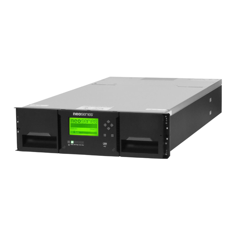
Operator Control Panel
The OCP is the LCD screen located on the front panel (13),
and displays actions and status information, menu items,
and error messages equivalent to the operation mode.
There are two modes:
• User interaction mode – This mode is employed when
a user is pushing buttons on the OCP.
• System driven mode – This is the normal mode of
operation where the OCP displays statuses associated
with the actions resulting from commands issued from
the host software application.
