P.A. VS1100 User manual

Ultimo aggiornamento: 30/09/21
1
P.A. – S.p.A. – EQUIPAGGIAMENTI TECNICI DEL LAVAGGIO
VIA MILANO, 13 – CASELLA POSTALE 115 – 42048 RUBIERA (REGGIO EMILIA) – ITALY
Tel. +39 0522 623611 – Fax. +39 0522 629600 – R.E.A. RE 156319 – R.I. RE11535 – Mecc. RE 013446
C.F. e P. IVA 01035950359 – Cap. Soc. i.v. € 750.000,00 – Codice Identificativo C.E.E. IT 01035950359
ART. 2497 –
BIS C.C. DIREZIONE E COORDINAMENTO BENETTI srl R.I. TRIB. DI RE 01480690351
. Web: http://www.pa-etl.it – E-mail: [email protected]
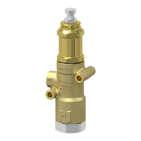
VS1100
- RELIEF VALVE - STAINLESS STEEL AISI 303
Suitable for use as a relief valve in high pressure systems.
DN 10
•
60.0680.00 VS1100 TYPE A
•
60.06** .00 VS1100 TYPE B
- Valve intended for professional use
- Stainless steel body AISI 303
- Stainless steel internal parts
- Totally protected moving parts
- Calibration protection (TYPE A)
TECHNICAL SPECIFICATIONS
CONSTRUCTION MATERIAL
BODY
:
AISI 303 Stainless steel
SPRING HOLDER:
nickel plated brass
SEALS
:
Hnbr
PART
NUMBER
RATED
PRESSURE
PERMISSIBLE
PRESSURE
MINIMUM
CALIBRATION
PRESSURE
MAX
TEMPERATURE
(1)
MAX
FLOW RATE
WEIGTH
INLET
OUTLET
bar psi bar psi bar psi °C °F l/min USG g oz.
60.0680.00
1000
14500
1100
15960
300 4350 100 212 40 10.6 2100
74.08 G 3/8” F
60.06**.00
1000
14500
1100
15960
300 4350 100 212 40 10.6 2100
74.08 G 3/8” F
1) The valve has been designed for a continuous use at a water temperature of 100°C (212°F).
It can work for short periods at a maximum temperature of 120°C (250°F)
DIMENSIONAL DRAWING

Ultimo aggiornamento: 30/09/21
2
INSTRUCTIONS
SELECTION
This product is to be used with clean water, even slightly mixed with normal detergents. For use with different or corrosive liquids,
please contact the PA Technical department. Appropriate filtration should be installed when using unpure liquids. Please make sure
that the valve is in line with the working data of the machine where it is to be installed (permissible pressure, maximum flow and rated
temperature of the system). In any case, the pressure of the machine must not exceed the permissible pressure marked on the valve.
OPERATION
The valve limits the maximum pressure in the circuit. In case of overpressure, a bypass port is opened through which the excess wa-
ter is discharged. During normal operation of the system, a spring-pulled shutter closes the bypass. The calibration pressure is ad-
justed by varying the spring thrust through the appropriate adjusting screw.
INSTALLATION
In a hot water machine, the valve should be mounted upstream of the boiler. In any case, even in cold water applications, if an
accidental overheating of the water is foreseen, the installation of thermal protection devices is advisable in order to keep the water
temperature below the maximum allowed temperature (MAX TEMPERATURE).
It is advisable to return the discharge flow to a tank. It is advisable for the tank to be equipped with baffles in order to reduce any tur-
bulence and air bubbles generated by the bypass flow, which could be damaging to the pump. When discharging in the atmosphere,
ensure to direct the valve properly in order to avoid serious injuries.

Ultimo Aggiornamento: 30/09/21
3
PRESSURE CALIBRATION
The valve is supplied not calibrated. The calibration should be carried out with the system in operation under pressure. The valve
calibration pressure is determined by operating on the adjusting screw (item 2): the calibration pressure is increased by turning the ad-
justing screw clockwise. Once the desired calibration pressure has been reached, lock the screw by tightening the nut (pos. 3).
It is possible (in Type A version) to seal the calibration with the anti-tampering cap (pos. 1) and its pin (pos. 1) and finally applying the
wire and the lead.
The relief valve should be calibrated at a pressure at least 10-15% higher than the working pressure of the system.
Abnormal operating pressure of the system causing repeated or continuous discharge of the relief valve could compromise the sealing
capacity of the valve itself.
MAINTENANCE
Once a year check the calibration of the valve, either directly on the machine or on a test bench.
After every discharge of the relief valve, please make sure that no debris are cumulated between the shutter and the seat.
In any case, even if no discharge occurred, a general servicing of the valve is advisable every two years. Check the wear condition of
the seals and interior components, and, if needed, replace them with original PA spare parts. When reassembling, lubricate with water-
resistant grease.
Maintenance must be carried out by qualified technicians.
The manufacturer is not responsible for any damage caused by improper installation and / or maintenance.
TROUBLE SHOOTING
PROBLEMS PROBABLE CAUSE REMEDY
Leakage from the bypass during the normal
operation of the system
- Damaged seat or shutter
- Impurity between seat and shutter
- Change
- Clean
NORMAL: see the Manual.
For a proper use, follow the instructions contained in this manual and re-write them on the Operation and Maintenance manual of the
machine where the relief valve is supposed to be installed.
This manual is valid for all valve types named VS 1100.
Technical data, descriptions and illustrations are indicative and may be modified without prior notice.
Instruction manual, maintenance, installation, spare parts.
n. MPA.0002EN

Last updated 03/11/2021
60.0680.00 VS1100 saf.valv.3/8F Bsp to bloc
Pos. P/N Description Q.ty K1K2K3K4 Pos. P/N Description Q.ty K1K2K3K4
1 60.1412.24 Spare kit knob 1 1
1 60.0598.41R Knob x block. press al-red 1 5
1 60.5114.31R 4 mm brass pin 1 5
1 13.1214.03R 14 mm lead seal ** 1 5
2 60.4307.51R Valve regulating screw, M14 sst. 1 2
3 11.4760.00R Hex. nut, M14 1 10
4 60.0685.31R Spring holder, brass 1 1
5 60.0652.31R Spring guide spacer, brass 1 2
6 60.0434.61R Spring, 8,5x38x80 mm black 1 3
7 60.0654.31R Spring rest pin, brass 1 2
8 10.4015.12R Back-up ring, 12,7x15,5x1,2 mm 1 • 10
9 10.3060.85R O-ring, 1,78x12,42 mm HNbr 85 1 • 10
10 10.3059.85R O-ring, 1,78x 11,11 mm HNbr 85 1 • 10
11 10.4012.14R Back-up ring, 11,2x143x1,2 mm 1 • 10
12 60.0684.51R Piston holder, Sst. 1 1
13 14.7443.10R Ball, 11/32" Sst. 1 10
14 60.0682.51R Piston, 10 mm Sst. 1 • 3
15 10.4006.09R Back-up ring, 6 x 9 x 3 mm 1 • 10
16 10.3049.85R O-ring, 1,78x 5,28 mm HNbr 85 1 • 10
17 60.0683.51R Seat, 5,8x13,9x6 mm Sst. 1 • 3
18 60.0681.55R Housing -VS1100 3/8 Bsp FF aisi303 1 2
** On request
Kit P/N Description
K1 60.0688.24 Spares kit -Vs 1100, 8x1pcs. 1
This manual suits for next models
1
Other P.A. Control Unit manuals
Popular Control Unit manuals by other brands

AMX
AMX HPX-AV100-RGB+A installation guide

Johnson Controls
Johnson Controls Penn P28 Series manual

ZURN
ZURN AquaSense ZTR Series Installation, operation, maintenance and parts manual

Emerson
Emerson Anderson Greenwood 81 Series Installation and maintenance instructions

Kovert
Kovert 22x PTZ instruction manual

Carotron
Carotron DIV280-000 instruction manual