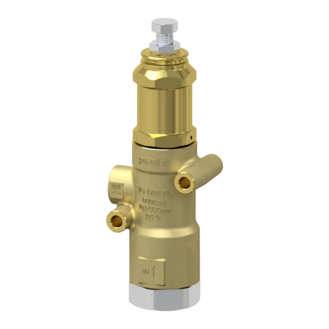
P.A. VS 80A/150 User manual

Last update: 30/11/2020
1
P.A. –S.p.A. –EQUIPAGGIAMENTI TECNICI DEL LAVAGGIO
VIA MILANO, 13 –CASELLA POSTALE 115 –42048 RUBIERA (REGGIO EMILIA) –ITALY
Tel. +39 0522 623611 –Fax. +39 0522 629600 –R.E.A. RE 156319 –R.I. RE11535 –Mecc. RE 013446
C.F. e P. IVA 01035950359 –Cap. Soc. i.v. € 750.000,00 – Codice Identificativo C.E.E. IT 01035950359
ART. 2497 –BIS C.C. DIREZIONE E COORDINAMENTO BENETTI srl R.I. TRIB. DI RE 01480690351
. Web: http://www.pa-etl.it –E-mail: i[email protected]
VS 80A/150-280 INOX 316 ATEX TechnicalManual: E228
Relief valve
TECHNICAL SPECIFICATIONS
Construction material
Body and internal parts made of stainless steel Aisi316.
Rated temperature
70°C –158°F
Nominal Diameter
DN15
PN
RATED
PRESSURE
PERMISSIBLE
PRESSURE
PRE-SET
PRESSURE
MAXIMUM
FLOW
WEIGHT
INLET
OUTLET
BYPASS
bar
psi
bar
psi
bar
psi
l/min
USGpm
g
60.0590.00
150
2200
170
2450
-
-
80
21
1180
1/2” Bsp F
60.0590.60
280
4050
310
4500
-
-
80
21
1210
1/2” Bsp F
•60.0590.00 TYPE B
•60.0590.60 TYPE A
▪Body and internal parts made of stainless steel
Aisi316.
CERTIFICATIONS AND STANDARDS
▪AtexDirective2104\34\EU
▪compliant

Last update: 30/11/2020
2
DIMENSIONAL DRAWING
SELECTION
This product is to be utilized with clean fresh water, even slightly additivated with normal detergents. For use involving
different or corrosive liquids, contact the PA Technical department. Appropriate filtration should be installed when using
impure liquids. Choose the valve in line with the working data of the machine where to be installed (permissible pressure,
maximum flow rate and rated temperature of the system). In any case, any over-pressure of the machine must not
exceed the permissible pressure marked on the valve.
OPERATION
The valve limits the maximum pressure of the system. In the event of over-pressure, this relief valve will open to allow
the liquid to by-pass. During normal system operation, a shutter driven by a spring will keep the bypass opening close.
The set valve pressure can be regulated by adjusting the spring load by means of the dedicated adjusting screw.
INSTALLATION
This product is intended to be incorporated on a finished machine.On a machine that produces hot water,this valve must
be fitted upstream the heat generator. In addition it is recommended to install devices that limit the fluid temperature
accidental increase.
DISCHARGE SYSTEM AND WATER ADDUCTION
It is advisable to direct the bypass discharge liquid to a baffled tank that will reduce possible turbolence and air bubbles
generated by the immission of the bypass flow, which could be harmful for the pump.
When large flow volumes, close tho the max flow rate, are used, it is not advisable to return the bypass liquid to the
pump as this may cause dangerous pressure spikes, dangerous for the pump.
PRESSURE ADJUSTMENT/SETTING
The valve is supplied without pressure setting. The setting is done with the system “on”and with pressure inside the
circuit. The valve setting pressure is achieved by operating on the adjusting screw (pos.7): by screwing it, the set
pressure will increase.Once the desired pressure is attained, block the screw by locking the counternut (pos.7)
TROUBLESHOOTING
PROBLEMS
PROBABLE CAUSES
SOLUTIONS
Leaking out the bypass port during
normal system operation.
- Seat or shutter is worn.
- Foreing material is jammed between seat
and shutter.
- Replace.
- Clean.
- System working pressure is above
the set pressure.
- Re-set the system
pressure.

Last update: 30/11/2020
3
REGULATIONS
See SAFETY NOTE SN03.
The accessory hereby described bears the CE marking in accordance with the standards and directives published in the
Declaration of conformity.
For a correct utilization, follow the directions described in this manual and re-print them on the Use and Maintenance
manual of the machine. If needed, ask for the original Conformity Declaration for the chosen accessory.
The present manual is valid for all unloader valves named VS 80/150 INOX 316 ATEX - VS 80/280 INOX 316 ATEX.
T.a.070° C
II 2 GD Ex h X
ATEX marking (see ATEX SAFETY NOTE SN03, PN: 10.9408.06)
SERVICING
The relief valve useful life is 10 years with general inspection and service after 5 years.
The life duration depends from the working conditions such as type of fluid, ambient and operating conditions (pressure
and temperature).
PA recommends to regularly service the relief valves every two years.
Any unauthorized servicing operation will cause the interruption of any “PA” responsability and
warranty on the product.
Technical data, descriptions and illustrations are indicative and liable to modification without notice.
Instruction manual, maintenance, installation, spare parts.
For a correct utilization, follow the directions of this manual.
Re-print them on the use and maintenance booklet of the machine.
n. 12.9228.00

DichCon_TF03_VS, rev. 00, 27/10/2020
DICHIARAZIONE DI CONFORMITÀ UE
EU DECLARATION OF CONFORMITY
Noi / We
P.A. S.p.A.
Via Milano, 13
RUBIERA (RE) –ITALY
dichiariamo sotto la nostra esclusiva responsabilità che l’apparecchiatura“Valvoladiscarico” tipo
we declare under our sole responsibility that the equipment “Relief valve” type
VS26A, VS43A, VS80A
Data di produzione: /
Date of production:
al qualequestoattestatosi riferisce,èconforme allaseguente DirettivaEuropea
to which this declaration refers, is in conformity with the following European Directive
2014/34/UE (ATEX)
2014/34/EU (ATEX)
La conformitàèstataverificata inbasedeirequisitidelle normeodeidocumentinormativi riportati nelseguito:
The conformity is under observance of the following standards or standards documents:
EN ISO 80079-36:2016
EN ISO 80079-37:2016
Marcatura / Marking:
II 2 G Ex h IIC T6 Gb
II 2 D Ex h IIIC T85°C Db
Ricevuta di deposito del fascicolo tecnico / Acknowledgement of receipt - EU:
XXXXXXXXXXXXXXXXXXXXXXX
Rubiera, dd/mm/yyyy
Firma del legale rappresentante
Legal representative signature

ATEX UNLOADER AND RELIEF VALVES
SAFETY NOTE
SN03
Rev. 00
Date 27/10/2020
Pag. 1 of 10
DOCUMENT REVISION
REV.
DATE
MODIFICATION
00
27/10/2020
First issue.
PREPARED BY
RGQ
(Quality manager)
Michele QUATTRONE
CHECKED BY
DUT
(Technical manager)
Fabio PEDRONI
APPROVED BY
AD
(Legal representative)
Arnaldo BENETTI

ATEX UNLOADER AND RELIEF VALVES
SAFETY NOTE
SN03
Rev. 00
Date 27/10/2020
Pag. 2 of 10
INDEX
1. INTRODUCTION........................................................................................................................................................... 3
2. DESCRIPTION OF THE PRODUCT ................................................................................................................................. 3
2.1 CLASSIFICATION & MARKING ............................................................................................................................ 3
2.2 FIELD OF APPLICATION ...................................................................................................................................... 4
2.3 TERMS USED...................................................................................................................................................... 4
3. INSTRUCTIONS FOR USE ............................................................................................................................................. 5
3.1 STORING, SHIPPING AND MOVING ................................................................................................................... 5
3.2 INSTALLATION ................................................................................................................................................... 5
3.2.1 WARNING...................................................................................................................................................... 5
3.3 FILTERING OF LIQUID ........................................................................................................................................ 5
3.3.1 CONNECTION & SETTING .............................................................................................................................. 6
3.4 USE & WORKING ............................................................................................................................................... 6
3.4.1 WORKING & ADJUSTMENT ........................................................................................................................... 6
3.4.2 SUITABLE & NON-SUITABLE USE ................................................................................................................... 6
3.4.3 DANGEROUS AREAS ...................................................................................................................................... 7
3.4.4 DANGER & POSSIBLE RISKS ........................................................................................................................... 7
3.4.5 PPE (PERSONAL PROTECTIVE EQUIPMENT) & PROCEDURES TRAINING ....................................................... 8
3.5 SYSTEM PROCEDURES ....................................................................................................................................... 8
3.5.1 TOOLS & MACHINERY ................................................................................................................................... 8
3.5.2 LOAD & UNLOAD........................................................................................................................................... 8
3.5.3 START & STOP ............................................................................................................................................... 8
3.6 INSPECTION, ORDINARY & EXTRAORDINARY MAINTENANCE, SERVICE & CLEANING ...................................... 8
3.6.1 PRECAUTIONS ............................................................................................................................................... 8
3.6.2 ORDINARY MAINTENANCE AND CLEANING.................................................................................................. 9
3.6.3 EXTRAORDINARY MAINTENANCE AND REPAIR............................................................................................. 9
3.6.4 INHIBITION AND RE-INSTALLATION OF THE VALVE .................................................................................... 10
3.6.5 REPLACEMENT OF PARTS & SPARES ........................................................................................................... 10
3.7 PREVENTION & REPRESSIVE ACTIONS (PRECAUTIONS) .................................................................................. 10

ATEX UNLOADER AND RELIEF VALVES
SAFETY NOTE
SN03
Rev. 00
Date 27/10/2020
Pag. 3 of 10
1. INTRODUCTION
PLEASE READ THE FOLLOWING INSTRUCTIONS CAREFULLY BEFORE INSTALLING ANY EC-MARKED PART (UNLOADER
OR RELIEF VALVE), ACCORDING TO THE ATEX PARTS DIRECTIVE 2014/34/EU IN A POTENTIALLY EXPLOSIVE
ATMOSPHERE AS DEFINED IN THE ATEX WORK ENVIRONMENT DIRECTIVE 99/92/EC. This manual must be brought to
the attention of the personnel working with the valve, and must be illustrated to the personnel qualified for
maintenance and repair of the valve. Any substantial modification to the valve will not be allowed.
Any substantial modification must be authorized by P.A. S.p.A. (for a broader definition of substantial modification,
please see maintenance manual).
2. DESCRIPTION OF THE PRODUCT
2.1 CLASSIFICATION & MARKING
The unequivocal identification of the equipment is to be verified by the data imprinted on the body and by the
declaration of conformity attesting that the valve has been produced using an evaluation, design and manufacturing
process which complies the essential safety requirements of Directive 2014/34/EU.
The assembler has the responsibility to verify the compliance with other EU directives.
The marking of the valve is:
II 2 G Ex h IIC T6 Gb
II 2 D Ex h IIIC T85°C Db
Ta: 0°C / +70°C
where:
Symbol CE Ex: in accordance with directive 2014/34/EU
Group II: suitable on surface
Category 2: suitable in zones 1 – 2 for gas and in zone 21 -22 for dust
Substance type: G (gas) and D (dust)
Specific type of protection: “Ex h” (construction safety)
Group of gas/dust: IIC (gas) and IIIC (dust)
Temperature Class/Max surface temperature: T6 (gas) and T85°C (dust) (see note 1)
EPL: Gb (gas) and Db (dust)
Ambient Temperature: 0 ÷ +70 °C
Acknowledgement of receipt - EU: XXXXXXXXX (the number will be communicated after the receipt)
Additional marking on equipment: material of the Seals: E – N – K – V (see note 2)
The measures of prevention and protection described in this manual do not determine the level of safety required if
the valves will not be used according to the provisional use, nor if they were not installed and subjected to
maintenance according to the terms of use or appropriate requirements.

ATEX UNLOADER AND RELIEF VALVES
SAFETY NOTE
SN03
Rev. 00
Date 27/10/2020
Pag. 4 of 10
2.2 FIELD OF APPLICATION
The valve is designed to be used with water up to 70 °C, with addition of mild detergents or disinfectants. In case of
use with special or even flammable liquids (different viscosity, chemical harshness or other), please contact our
technical department. The valve shall be used within pressure and temperature reported in the official documents,
such as declaration of conformity, certificate of assembly and technical data reported on the instruction manual.
The fluid shall have an ignition temperature of minimum 50 K over the maximum exterior temperature of the
appliance’s surface where the cleaning liquid is utilized.
The ambient temperature when the appliance is working shall range between 0 ÷ +70 °C. For a different use, please
contact the manufacturer for a customized study.
Only when it’s used according to the prescriptions included in this manual and in correctly tackling residual risks
raising from its use, does this valve assure a level of protection high enough as to not generate potential sources of
priming, when installed in a potentially explosive environment.
The appliance in question grants that potential sources of priming are not activated in normal functioning and even in
case of foreseeable and rare failure or malfunction.
Breakage or failure to the appliance can happen. In that case, it is necessary to check the causes of failure. When
these are traced down to the appliance, they must be removed.
Note 1: the appliance reaches a maximum surface temperature according to the temperature of the fluid pumped in.
The temperature class must take into account the safety factor 0,8 aimed for appliances of class 1, see table below.
FLUID TEMPERATURE
°C
TEMPERATURE CLASS
(GAS)
MAX EXTERIOR SURFACE TEMPERATURE
(DUSTS)
0 to ≤ 70
T6
T85 °C
Note 2: the cleaning liquid is to be chemically compatible with the seals that have been assembled by the manufacturer
of the appliance. The marking will identify the material of the seals, as per the following chart:
MARKING ON THE EQUIPMENT
MATERIAL OF THE SEALS
E
EPDM
N
HNBR
K
FFKM
V
FKM
Compatibility (category - zoning) between the valve and the environment must be established by the user according
to exact and specific considerations Directive 99/92/EC.
It is not allowed to use the valves in potentially explosive atmospheres in underground and mining areas, EPL Ma and
Mb (group I category M1 and M2).
2.3 TERMS USED

ATEX UNLOADER AND RELIEF VALVES
SAFETY NOTE
SN03
Rev. 00
Date 27/10/2020
Pag. 5 of 10
Qualified/Specialized Technician: personnel who was trained for installation, adjustment, maintenance, repair. It is
required that the technician shall be trained and allowed to perform such tasks, and to have specific knowledge not
only of the tool and the risks stemming from its use, but also the possible risks of the appliance in question.
Temperature Class (T): it is the maximum superficial temperature of the appliance (taking into account also the safety
coefficient as reported in UNI CEI EN ISO 80079-36:2016. It also corresponds to the max. surface temperature of the
valve.
3. INSTRUCTIONS FOR USE
3.1 STORING, SHIPPING AND MOVING
The valves are supplied with adequate packaging. The unloading and moving of the tools shall be carried out by
trained personnel, who is also responsible for checking that the order and the freight match.
It is necessary to carefully move the valve to avoid shock impacts, and therefore, possible deformations and cracks
which could successively determine leaking of the product contained through the attachment points of the valve a/w
possible trigger source (sparks, adiabatic compression, etc.).
Localities of Warehouse storage, conservation, transport and movement of the valves must guarantee that they are
not subject to shock impacts, tumbles, deterioration and other damaging which could compromise the function of the
valve.
Any eventual damage must be immediately communicated to P.A. S.p.A. for assessment.
3.2 INSTALLATION
3.2.1 WARNING
Each installation or reinstallation must be performed by qualified personnel, duly trained and informed on the related
risks, even concerning the instructions of this document.
When using the utensils do not apply excessive force rotation on the connections in the presence of a potential
explosive atmosphere.
The use of utensils in zone 1/21 and 2/22 is allowed with particular instructions under the directive UNI CEI EN ISO
80079-36:2016 which has to be known by the operator.
Installation errors can provoke deformation or structural collapse of the pipe connection, also a loss of fluid in the
ambient.
Installation errors can compromise the regular movement with effective possibility of sparking.
During installation, keep to the direction of flow indicated by the arrows on the valve body and on the construction
drawings.
3.3 FILTERING OF LIQUID
The fluid sent from the system to the valve has to be filtered in order to prevent particles to slip through causing
malfunction and therefore frequent maintenance interventions. The recommended sealed filter has to be at least 300
microns. We recommend to clean it every 100/300 hours and, in case of filter breakage, replace it.

ATEX UNLOADER AND RELIEF VALVES
SAFETY NOTE
SN03
Rev. 00
Date 27/10/2020
Pag. 6 of 10
3.3.1 CONNECTION & SETTING
The valve must be connected to a pressure application, usually fed by piston pumps, pressure washers and similar; in
order to prevent possible damage to persons and things, where such an application must be equipped with all safety
parts and control (like safety valves, regulating etc.) foreseen by the directives in force. Use a resistant and adequate
sized tube for the connection, possibly avoiding narrow necks and abrupt direction variations to restrain the pressure
loss.
The valve must be anchored firmly by an appropriate support. This type of valve must be held and fed by a fixed pipe
that prevents any swinging.
The connecting tube to the valve must be of such to help the fluid flow without any excessive pressure drop.
The assembler is compelled also to carry out the inspection of all the connection links.
The apparatus must be installed by the following procedure:
Assure that there is no obstacle placed between valve and attachment; place a suitable gasket that assures a
seal age conform and a protection grade minimum IP54 for Gas and IP6X for powders.
Insert the connection tubes (entry and exit) following a good technique and using acknowledged
components, adopting the foreseen clamping instructions.
During the connection of the tubes, make an electrical earth link-up with a minimum cable size 4mm
observing the prescribed terms for equipotential connections.
Inspection after installation, to be carried out by the assembler or end user, in particular the perfect coupling
of usage at the various openings (keep to the limit levels of emission rated in the zoning phase).
3.4 USE & WORKING
3.4.1 WORKING & ADJUSTMENT
The function of the unloader valve is to prevent the risk of overpressure by automatically releasing the overpressure
towards the by-pass line when the pressure exceeds the set value.
The function of the relief valve is to discharge excess fluid to the inlet system when the pressure of the protected
equipment exceeds the maximum allowable pressure values for expressly non-ordinary reasons of operation
(incorrect maneuver with excess pressure and excess temperature, also caused by external fire).
This function takes place with the direct discharge into the atmosphere without the need for drainage with the direct
discharge pipe into the atmosphere, or with recycling in the collection and replenishment system water tank.
The valves intent is to be assembled into a set whose destination has industrial, technological and production
purposes.
The procedures to observe during function concern the process levels and correct running.
3.4.2 SUITABLE & NON-SUITABLE USE
The cleaning liquid should have an ignition temperature of minimum 50K over the maximum exterior temperature of
the appliance's surface where the cleaning liquid is utilized. (T=70 °C).
It is forbidden to make substantial modifications to the valve (replacement of parts not recognized by P.A. S.p.A. or
assembly variations). In the other cases of ordinary & extraordinary maintenance and repairs, refer to the
maintenance manual.

ATEX UNLOADER AND RELIEF VALVES
SAFETY NOTE
SN03
Rev. 00
Date 27/10/2020
Pag. 7 of 10
The Company P.A. S.p.A. declines all responsibility for damage to persons, animals or things derived by an improper
use of the apparatus a/o the non-observance of the dispositions contained in the present manual.
3.4.3 DANGEROUS AREAS
Particular attention has to be reserved to any area potentially explosive around the valve and also from the inside. Do
not open the valve in areas potentially explosive and during working. Before opening the valve, disconnect it from the
machine and bring it to a safe area.
It is severely forbidden to operate on the tightening components and on the apparatus connections whilst running
and in any case each time it is predictable that the area may contain a potentially explosive ambient.
3.4.4 DANGER & POSSIBLE RISKS
Hot surfaces
The valves always present the danger of hot surfaces due to the maximum temperature of 90°C: always check that the
internal fluids and external areas cannot trigger off at such a temperature. The surface temperature must not be
higher than 80% of the minimum temperature ignition of the Gas measured in ° C.
Naked flames and hot gas
Naked flames and hot gas are forbidden around the valve.
Mechanical sparks
Sparks have to be excluded during a normal function even if they can occur in case of foreseen and rare dysfunctions;
they can be caused by friction, knocks or abrasion, hammering.
Ultrasounds (acoustic danger)
Tank measurement is forbidden when the valve is in function.
Electric currents and protection against cathode corrosion. Static electricity
Earth connect all the wires which could dangerously charge through certain connection points.
The installer is responsible for checking that there are no insulated metal parts.
The User must regularly check the effectiveness of the ground connection.
Adiabatic compression and shock waves
The process that can cause adiabatic compression or shock waves are not tolerated. Verify the normal function of the
wash fluid in the adduction systems.
Exothermic/Endothermic reactions, including self-ignition of powders
Wash fluids with endothermic characteristics or reactive with water and impurities are forbidden.
Excessive vibrations and stress
Stress derived from vibrations, especially transmitted by the tube connections and other connected apparatus are
forbidden; where such conditions cannot be guaranteed, appropriate measures must be taken to reduce to the
minimum such phenomena.
Back pressure
An elevated back pressure to the nozzles acts negatively on the valve compromising the set calibration. The nozzles
must be exempt from back pressure: They must not be blocked and no flow from the nozzles towards the inside of the
valve is permitted.

ATEX UNLOADER AND RELIEF VALVES
SAFETY NOTE
SN03
Rev. 00
Date 27/10/2020
Pag. 8 of 10
Ambient risks
Ambient conditions different than those specified can cause a danger source.
They can cause dangerous service conditions (with relation to the processed fluids) an abrupt movement, humidity
effects, ambient temperatures and pressure changes, chemical agents, corrosion.
The working process in the installations must be carried out in such a manner to be not determined by a dangerous
influence.
Refrain from the functioning of the valve in case of evident irregularities. The rupture of some components provokes a
non-hydrokinetic function of the valve.
3.4.5 PPE (PERSONAL PROTECTIVE EQUIPMENT) & PROCEDURES TRAINING
The choice of PPE (Personal protective equipment) is user’s responsibility according to the local safety regulation,
predicting the following residuary risks:
Hot surface temperatures
Electrostatic charges
Infiammable liquids, noxious substances, etc
Others in relation to type of use
The use of the valve must foresee a precise training formation.
It is necessary to pertain to the application of the local safety regulation.
3.5 SYSTEM PROCEDURES
3.5.1 TOOLS & MACHINERY
The safety of the system is also in function with control devices (conform with Directive 2014/34/EU) which must be
absolutely independent from the valve.
3.5.2 LOAD & UNLOAD
Adequate means are foreseen for the draining and leakage in order to consent the cleaning operations, inspection and
maintenance in absolute safety conditions.
3.5.3 START & STOP
In case of doubt and an irregular function, stop the productive process, do not make brief repairs and ask qualified
personnel.
3.6 INSPECTION, ORDINARY & EXTRAORDINARY MAINTENANCE, SERVICE & CLEANING
3.6.1 PRECAUTIONS
Before proceeding to the periodic procedures of inspection, maintenance, repairs & cleaning it is necessary to
discharge the internal pressure, through a duct converged in a safe area, to avoid damage to persons or things and
to verify the occurred discharge phase by means of control devices (pressure gauges).

ATEX UNLOADER AND RELIEF VALVES
SAFETY NOTE
SN03
Rev. 00
Date 27/10/2020
Pag. 9 of 10
It is always necessary to verify the non-existence of potential explosive atmospheres and the impossibility to trigger
off.
The user must certify that the operator is opportunely instructed to carry out all the safety procedures & hygiene in
the work areas according to the protocol in order to avoid any eventual risks deriving from the operations mentioned
above.
3.6.2 ORDINARY MAINTENANCE AND CLEANING
The cleaning stages are to be carried out regularly depending on the use and are obligatory in situations where foreign
bodies and/or exploding powders are present on the valve and on the drains ((independently from the settled
thickness).
Before carrying out periodic cleaning operations, it is absolutely essential to release the internal pressure on the
protected equipment by means of the relevant pipe into a safe zone to avoid uncontrolled atmospheres being
generated; verify that the unloading phase is complete by means of control devices. Then disconnect the service
connections using the methods required for the use of tools and completely empty the valve of all the product inside
it.
For internal and external cleaning, it is necessary to use non corrosive products or solutions, suitable to remove the
work residue, and that do not damage the O-ring surfaces. For the cleaning operations do not use aggressive chemical
detergents a/o mechanical systems that can cut or deform the valve.
The above operations must not jeopardize the alignment of the internal parts and the seal between seat and
valve shutter/sphere.
For the cleaning operations, do not use aggressive chemicals and/or mechanical systems that can
cut into or deform the valve.
Before reusing and/or reinstalling the VALVE, after washing or general maintenance or any other operation
deemed necessary, carry out the procedure provided in point 3.2.
3.6.3 EXTRAORDINARY MAINTENANCE AND REPAIR
Please check the internal parts every 300 / 400 hours of work in order to verify any premature wear of the parts.
Replacement of the dynamic seals is recommended:
VB23A-280: pos. 9-10 and 21
VB26A-280: pos. 6-7 and 19
VB33A-280: pos. 5-6 and 19-20
VB43A: pos. 6-7 and 18
VB80A: pos. various, identified with letter A
VS26A: pos.5 and 9-10
VS43A: pos. 7 and 16
VS80A: pos. various, identified with letter A
Verify that the slide surfaces of the seals are in good conditions: replace the parts if worn out or if damaged.
Use only original “PA” spare parts.
Lubricate only with silicone grease (14.6552.00) and do not use mineral grease or oil otherwise internal parts will be
subject to rupture.

ATEX UNLOADER AND RELIEF VALVES
SAFETY NOTE
SN03
Rev. 00
Date 27/10/2020
Pag. 10 of 10
If exposed to freezing temperatures, make sure that the valve is completely emptied after use in order to prevent the
freeze.
For all details regarding assembly and disassembly of the valve, please see the Maintenance Manual.
3.6.4 INHIBITION AND RE-INSTALLATION OF THE VALVE
For a working order inspection of the apparatus or for maintenance/replacement, the removal of the valve from the
application is permitted only when the apparatus is not under pressure and in the absence of a potential explosive
atmosphere.
Before reusing or reutilizing the valve after washes, general maintenance or any other necessary operation, follow the
warnings as seen on paragraph 3.2.1. of this safety note
After reinstalling the device, and before placing the equipment under pressure, verify the correct tightness between
the connections and apparatus and its efficiency.
3.6.5 REPLACEMENT OF PARTS & SPARES
It is necessary to replace the valve and/or its components when, upon the user’s discretion, the safety functions are
not guaranteed during working. The replacement of valve parts with others not identical to those original cannot
guarantee the design conditions established by P.A. S.p.A.
3.7 PREVENTION & REPRESSIVE ACTIONS (PRECAUTIONS)
The user must use suitable measures to eliminate a/o reduce potential explosive atmospheres externally to the valve
applying the Directive 99/92/EC.
The user must pertain to what established in order to:
Avoid, however possible, the formation of explosive atmospheres (concentration-classification limits of the
areas);
Choose qualified control systems;
Avoid the creation of lively trigger sources (prevention).

Last updated 04/11/2021
60.0590.00 VS80/150 safety valv. 1/2F Bsp Ai316-Atex 60.0590.60 Vs80/280 safety valv. 1/2F Bsp Ai316-Atex
Pos. P/N Description Q.ty K1K2K3K4 Pos. P/N Description Q.ty K1K2K3K4
1 60.0432.60R Piston, M10 aisi316 Sst. 1 3
2 10.4014.00R Back-up ring, opn. 18x13,5x1,2 mm 2 • 10
3 10.3178.10R O-ring, 2,62x13,1 mm Vi 70 1 • 10
4 10.3072.10R O-ring, 1,78x20,35 mm Vi 70 3 • 10
5 60.0404.60R Piston holder, aisi316 Sst. 1 3
6 60.0412.61R Spring, 7,5x35x70 mm blue (1) 1 10
6 60.0411.61R Spring, 6,5x33x70 mm white (2) 1 3
7 11.4627.50R Hex. nut, M10, Sst. 3 10
8 60.0406.31R Spring holding washer, brass 1 10
9 10.3174.10R O-ring, 2,62x9,93 mm Vi 70 1 • 10
10 10.4015.00R Back-up ring, 10x14,5x1,2 mm 1 • 10
11 15.1032.00R Roll pin, 3x18 mm Sst. 1 10
12 60.0405.60R Suction coupl., 1/2F Bsp aisi316 Sst. 1 3
13 60.0410.60R Spring, 1,6x11,5x20 mm aisi316 Sst. 1 5
14 14.7461.01R Ball, 13/32" Sst. ai.316 1 • 10
15 10.3060.10R O-ring, 1,78x12,42 mm Vi 70 1 • 10
16 60.0408.60R Seat, 8,5x15,9x4,5 mm aisi316 Sst. 1 • 3
17 60.0413.51R Plug,sst. 1/2 Bsp, hex.27 1 3
18 14.4101.00R Sealing washer, 1/2 Bsp 1 10
19 60.0431.60R Housing -VB80, 1/2F Bsp aisi316 Sst. 1 1
20 60.0552.51R Plug, sst. M24x1,5, hex.27 1 5
Kit P/N Description
K1 60.0596.24 Spares kit -VB80, aisi316 Sst. 8x1pcs. 1
(1) 60.0590.60 (2) 60.0590.00
This manual suits for next models
3
Table of contents
Other P.A. Control Unit manuals
Popular Control Unit manuals by other brands

Hirschmann
Hirschmann PTN-4-DSL-LW user manual

Avnet
Avnet Qseven MSC Q7-BT user manual

Sartorius
Sartorius YCM20MC Series installation instructions

BENDIX
BENDIX LQ-3 LQ-4 FRONT AXLE RATIO VALVE manual

Freescale Semiconductor
Freescale Semiconductor NXP TWR-LCDC-EPSON quick start guide

Advanced Energy
Advanced Energy Thyro-PX Anybus Modbus TCP Guide