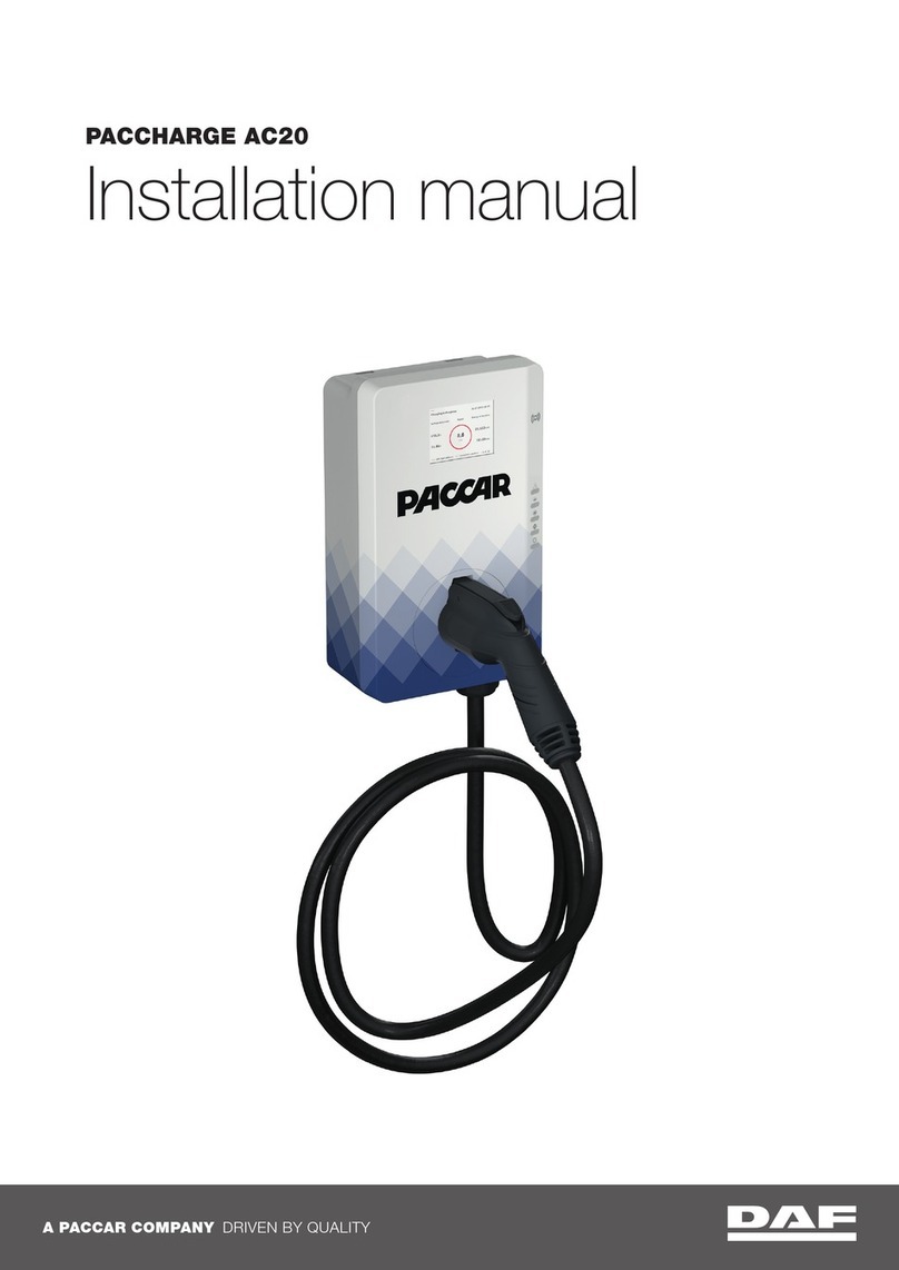
Paccar DAF POWERCHOICE 250A User manual

A PACCAR COMPANY DRIVEN BY QUALITY
Installation manual
POWERCHOICE 250A DISPENSER

Copyrights
All rights to copyrights, registered trademarks, and
trademarks reside with their respective owners.
Copyright © 2022 PACCAR/Heliox
Notice
This document contains information about one or more
PACCAR/Heliox products and may include a description of or
a reference to one or more standards that may be generally
relevant to the products. The presence of any such
description of a standard or reference to a standard is not a
representation that all of the PACCAR products referenced in
this document support all of the features of the described or
referenced standard. In order to determine the specific
features supported by a particular PACCAR product,
the reader should consult the product specifications for that
particular product.
PACCAR/Heliox may have one or more patents or pending
patent applications protecting the intellectual property in the
PACCAR products described in this document.
The information in this document is subject to change without
notice and should not be construed as a commitment by
PACCAR. PACCAR assumes no responsibility for any errors
that may appear in this document. In no event shall PACCAR
be liable for direct, indirect, special, incidental or
consequential damages of any nature or kind arising from the
use of this document, nor shall PACCAR be liable for
incidental or consequential damages arising from use of any
software or hardware described in this document.
This document and parts thereof must not be reproduced or
copied without written permission from PACCAR/Heliox and
the contents thereof must not be imparted to a third party nor
used for any unauthorized purpose.

Contents
1Preface
1.1
1.1.1
1.2
About the document
Structure of this document
Target groups
4
4
4
4
4
2Introduction
2.1
2.2
2.3
2.4
Site layout considerations
Distance from dc outlet column to base station
Floorplan
Install options
5
5
5
6
7
3Civil work and mechanical installation
3.1
3.1.1
3.2
3.2.1
3.2.2
3.3
3.3.1
3.3.2
3.3.3
3.4
3.5
3.6
Prepare for installation
Preparation
Wall mount
Installation kit
Install the column against the wall
Install the base frame + foundation
Installation kit
Preparations
Install the base frame
Install base frame on the floor
Install base frame on the floor with chemical anchors
Install the column on the base frame
8
8
8
9
9
10
11
12
12
13
14
14
14
4Electrical installation
4.1
4.1.1
4.2
4.2.1
4.2.2
4.2.3
4.3
Preparation
Switch off base product
Overview of connections to be made
Charge column ccs2
Connecting charge column
Multiple dc outlet columns
After installation test
15
15
15
16
16
17
18
19

4
1. Preface
About the document 1.1
This document is part of the technical handbook which is an integral part of the DC outlet column.
This section gives the requirements and instructions for the installation of the DC outlet column
250A CCS type-2.
The information given in this document is meant for use by the authorized persons who are
involved with the planning, supervision and execution of the given tasks. These tasks are, but not
limited to, handling, transport, storage and the installation.
For the execution, different skills and authorizations are required. For material not covered in this
manual, please refer to the introduction document to find the proper section of the handbook
to reference.
Work involved with the EVSE (base station and DC outlet column) calls for the safe work
procedures with and in the vicinity of electrical installations.
Target groups
1.2
4
Structure of this document
1.1.1
This document gives an installation instruction of the DC outlet column. For easy access to the
information, this document is divided into chapters.
The chapters are:
•the introduction;
•the civil work, to detail the pad and foundation work to be done;
•the mechanical installation, to detail the lifting, mounting and installation work to be done;
•the electrical installation, to detail the electrical work to be done.

5
2. Introduction
The installation of the DC outlet column requires administrative work to obtain the required permits as
well as civil work to excavate the trenches for the foundation, conduits, ductbanks, cables, and other
underground needs. Contact your local authorities and follow local processes to obtain the necessary
permits.
For locations where the DC outlet column is exposed to the possibility for collisions with vehicles,
consider the installation of collision prevention equipment.
After completion of the civil work, the DC outlet column can be installed. When the mechanical work is
completed the DC outlet column should be electrically connected and commissioned.
Overall cable length from base station to the most distant DC outlet must be ≤ 100m.
Site Layout Considerations
Distance from DC outlet column to base station
2.1
2.2
•There are several aspects to locating the DC outlet equipment at a macroscopic scale that
improve performance, lifetime, and ease of operation. These items are very dependent on the
end user’s site and intended use, so they are covered as concept considerations in this section.
•The access of the installation site shall be of sufficient size to allow the transport packages for
the DC outlet equipment to pass. If the access doors/gates/corridors are too small for the safe
transport of the transport packages, special provisions may need to be made to allow
installation. The maximum size of the DC outlet package is 120x80x140cm.
•For locations where the DC outlet is exposed to direct sunlight and high ambient temperatures
for most of the day, it is required to install protection from direct sunlight or place the DC outlet
under shade.
•For locations where the DC outlet is exposed to the possibility for collisions with vehicles, it is
highly recommended to install collision prevention equipment. This may be in the form of
bollards or a significantly raised curb.
•For locations with significant snow accumulation or snow drifts, it’s recommended to install
barriers or a shelter to protect snow from blocking air intake vents. Airflow needs should be
respected in all installations. The DC outlet is air cooled by a set of internal fans which take in
the air from the ventilation grids in the bottom of the cabinet and release the warm air from the
ventilation grids in the top of the cabinet. The air intake has filters to prevent contamination of
the internal side of the cabinet. Keep the ventilation grids free from debris and obstacles to
allow for a free flow of air.
•The maintenance tasks for the DC outlet are done from the top and the front of the cabinet.
Consider this when spacing units and planning service with vehicles present.
•The operation area is at the front of the cabinet. Normally, the charging process is started,
monitored, and stopped automatically by the EV. In case of abnormal operation, it is possible to
stop the charging process with the Charge abort button or the emergency stop button.
•The escape routes are very location specific and shall comply with the national and local rules
and regulations. Keep in mind that a safe escape route is provided during the maintenance
tasks (with the door open).
•The cabinet can be connected to another external DC outlets by daisy chain. Even if these are
not initially all deployed, reservation of space is prudent to allow future expansion.
Note:
If a distance beyond 100m is required, consult Heliox for the possibilities.
Floorplan 2.3
The DC outlet column is designed to be mounted on the floor. The figure shows the top view.
Maintenance area
Escape area
* Because of cables on the right side of the cabinet and maintenance activities on the left side, a
clearance of 500 mm on both sides is recommended.
450 mm
50 mm250 mm
500 mm*
450 mm700 mm
500 mm*
Charging
column
6

Install options 2.4
The DC outlet columns can be installed in two ways:
- Single column
- Daisy chain¹
The (mechanical) installation options:
1. Wall mount See paragraph 3.2 Wall mount for
civil work and mechanical installation.
2. Base frame + foundation See paragraph 3.3
Install the base frame + foundation and 3.6
Install the column on the base frame for civil
work and mechanical installation.
3. Concrete mount See paragraph 3.4 Install base
frame on the floor or 3.5 Install base frame on
the floor with chemical anchors for civil work
and mechanical installation on the floor.
After that see paragraph 3.6 Install the column
on the base frame
¹ Daisy chain is a term that describes the ability to connect a series of devices together using a
single connection between two devices.
7

3. Civil work and mechanical
installation
The civil work and mechanical installation require hoisting or lifting tasks that may require multiple
people or machines for that purpose.
It is the sole responsibility of the installer, to make sure:
•the mechanical installation work is executed in compliance with the, local and national Codes,
Directives, Standards, Rules and Regulations;
•the hoisting and lifting work is executed by certified persons and with appropriate equipment.
Danger:
Failing to adhere to these points may result in a variety of consequences from
damaged equipment to personal harm or death.
Caution:
Be careful when you handle the coated and painted parts. Damaged coating can
cause corrosion. Corrosion can cause serious damage to the parts.
8
Prepare for installation 3.1
1. Put the pallet with the cabinet on a flat and stable surface with sufficient space to work.
2. Remove and discard the packaging material.
3. Dispose of the packaging material in accordance with the local regulations.
Preparation
3.1.1

Wall mount 3.2
9
Installation kit
3.1.1
Quantity
Description
2
Mount bracket
4
Washer DIN267 M8
4
Bolt DIN912 M8 x 20
1
Gland plate + seal HE2121033-01
Quantity
Description
4
DIN571 10 mm (length to be
determined at location)
4
DIN9021 M8
Appropriate plugs for DIN571
10mm
*
Gland M32 x 1.5
*
Gland M25 x 1.5
*
Gland M20 x 1.5
*
Gland M16 x 1.5
*
Blind plug M32 x 1.5
*
Blind plug M25 x 1.5
*
Blind plug M16 x 1.5
Not included in the installation kit:
* Number of glands depend on daisy chain.

Install the column against the wall
3.2.2
1. Mark drill holes.
2. Drill holes for appropriate plugs for fixation
screws DIN571 10 x (xxx) mm
3. Fixate the bracket with bolds and washers that
came with the installation kit.
4. Unscrew the 2 screws on top of the hood.
5. Take off the hood.
6. Fixate the top bracket wit DIN912 M8x20 + M8
washer.
7. Mount column at bottom bracket.
Fixate with DIN912 M8x20 + M8 washer.
8. Mark needed drill holes.
9. Unmount column from bottom bracket.
10. Drill appropriate holes at marked spots for
the plugs.
11. Place the plugs and mount the column at the
bottom bracket again.
12. Fixate top bracket to the will with DIN571
10x150mm screws and DIN9021 M8 washers.
13. Place the hood again and fixate it.
10

14. Fixate the gland plate.
15. Mount needed glands
16. Close not used gland holes with blind plugs.
17. Place cable conduit (if applicable).
Install the base frame
+ foundation
3.3
11

Installation kit
Preparations
3.3.1
3.3.2
There is no installation kit for this option. All bolts and nuts are included.
1. Dig a hole to fit the foundation.
Measurements of the foundation:
l x w x h = 500 x 300 x 695 mm.
2. Install the foundation with the top
max. 50 mm below pavement.
Place concrete block at the bottom
of the foundation.
Try to install with minimal tilt.
3. Install the conduits in such way that top of
conduit is at least 50 mm above pavement
level.
4. Fill the foundation with sand.
Make sure its fully filled and secured.
5. Now install the wires and cables in the
conduits first. See infra structure of system
what wires and cables are needed.
Max 50 mm
Min 50 mm
Top view
12

Install the base frame
3.3.3
1. Install the threated rods with washers and
nuts onto the foundation.
2. Unscrew the (4) top nuts and washers.
3. Align the 4 nuts in desired height to level the
base frame (and eventually the column).
4. Unscrew the 4 screws of base frame to
remove the front.
5. Install the base frame and fixate it with use
of washers and nuts (4x)
Align height
13

Install base frame on the floor
with chemical anchors
Install the column on
the base frame
3.4
3.5
3.6
300 mm
255 mm
115 mm
160 mm
1
2
3
4
5
M8 M8M6M6
M8 M8M6M6
1. Unscrew the 4 screws of base frame to
remove the front.
2. Mount the base on the floor.
Use 4 threaded rods. Make use of:
- plinth under ring (1)
- threaded rod M10 (2)
- nut M10 (3)
- flat washer (4 and 5)
Mount the base with chemical anchors:
•Drill the holes (10mm), use the mold.
•Apply the chemical anchor.
•Mount the base.
Install the cabinet and fix it with use of
washers and nuts: 4 x M8 + 4 x M6.
14

Danger:
Risk of electrocution. Make sure, it is safe to work on the electrical installation.
Energized electrical systems are hazardous and can cause electrical shock. Electrical
shock can cause (serious) injury to persons.
Danger:
Lock-out/tag-out is required and verification of no voltage
is required.
4. Electrical installation
15
Note:
When connecting cables:
1. Where possible allow for sufficient over length for future repair of the
connections.
2. Where possible make sure, sufficient length is available for 3x a repair session.
3. Adhere to the minimum bending radius of 5x the cable diameter
4. Install the cables in accordance with the manufacturer's instruction.
Note:
All cables/wires from the base station will enter the DC outlet column via an opening
in the bottom. It is possible to remove the panel of the base easily to have good
access during installation of the DC outlet column and all the cables/wires.
Preparation 4.1
Switch off base product
4.4.1
1. De-energize base product by switching off main and auxiliary
circuit breakers. Ensure that no voltage is present at feeding
output wires. See documentation of the Base product.
2. Lock-out/Tag-out the base product and the related systems to
prevent that the base product can get energized unintentionally.
3. Make sure, the electrical parts and connections are clean, dry
and free of corrosion
4. Wait 5 mins before opening the base product / DC outlet
due to the discharge time of the capacitors.

The power connections are located behind the control panel (1). Use the rotary knob (2) on top
and bottom to open the panel to access the connections.
The DC connections are highlighted:
Max. cable cross section 125 mm2.
Max. 2 cables per connection (daisy chain).
The earth connection is just below the
DC connections:
Charge column CCS2
4.2.1
Overview of connections to be made
4.2
16
Note:
A backing wrench is required when making high current connections at contactors.
It is imperative that no torque is transferred to the contactor chassis.

Connecting charge column
4.2.2
X500:1
X500:3
X500:5
X500:7
X500:9
X500:11
X500:GND (PE)
X500:2
X500:4
X500:GND (PE)
X500:6
X500:8
X500:10
X500:12
X500:13
X501:1
X501:3
X501:5
X501:7
X501:9
X501:11
X501:GND (PE)
X501:2
X501:4
X501:GND (PE)
X501:6
X501:8
X501:10
X501:12
X501:13
Charge column connections
* connected when daisy chained
Cable
Function
DC Outlet input
connection
DC Outlet output
connection
AC input and output
L1
X500:1
X501:1
L2
X500:2
X501:2
L3
X500:3
X501:3
N*
X500:4
X501:4
GND (PE)
X500:GND (PE)
X501:GND (PE)
CAN input and output
CAN_H
X500:5
X501:5
CAN_L
X500:6
X501:6
Shield
200SH2
201SH2
Low voltage interface
X500:7
X501:7
X500:8
X501:8
X500:9
X501:9
Emergency stop input
and output
X500:10
X501:10
Interlock (door switch)
input and output
X500:11
X501:11
X500:12
X501:12
Ethernet input and
output
Communication
X500:13
X501:13
DC+ input and output
DC+
110Q5 A1+
connection flag
110Q5 A1+
connection flag
DC- input and output
DC-
110Q6 A2
connection flag
110Q6 A2-
connection flag
GND (PE) input and
output
GND (PE)
GND (PE) bonding
bolt
GND (PE) bonding
bolt
17

Multiple DC outlet columns
4.2.3
Charge
Column A
Charge
Column B
Input (X500) Output (X501)
EVSE
CP, PE,
DC+/-
CP, PE,
DC+/-
In case there are more DC outlet
column. The columns must be
connected as shown. All required
connections towards DC outlet
column B will be routed directly
via DC outlet column A and not
via the base station.
18

19
After installation test
4.2
1. Make sure, visually and by measurement, the
connections are made correctly.
The connections are torque tight and marked.
2. Make sure, it is safe to do the resistance test
with the use of valid, calibrated equipment.
3. Validate the operation of the resistance tester.
4. Measure the contact resistance between cable
lug and connected component (matching
colors indicates measuring points).
5. The measurement should read less than
0.05mΩ.
6. Make a note of the results and keep them with
the Charge column.
7. If the resistance measurement fails the
specifications, contact the Heliox service
department for advice on how to proceed.
8. If the test fails, do any necessary work.
9. Close the cabinet.
10. Mount the front panel of the base.
11. Switch off main switch in cabinet until the
charging column is commissioned.
Note:
Installer is responsible for closing
possible holes in the foam seal
between base and cabinet.

A PACCAR COMPANY DRIVEN BY QUALITY
IATF16949
Quality
Management System
ISO14001
Environmental
Management System
DAF Trucks N.V.
Hugo van der Goeslaan 1
P.O. Box 90065
5600 PT Eindhoven
The Netherlands
daf.com
All rights to copyrights, registered trademarks, and trademarks reside with their respective owners.
Copyright © 2022 PACCAR/Heliox. All rights reserved.
EN-1021
Table of contents
Other Paccar Automobile Batteries Charger manuals
Popular Automobile Batteries Charger manuals by other brands

FRONIUS
FRONIUS Wattpilot Go 11 J quick start guide

CRAIG & DERRICOTT
CRAIG & DERRICOTT SMART ION CHARGE EV03221000 Installation & maintenance

Easee
Easee Home quick start guide

Circontrol
Circontrol eVolve Smart Series user manual

Black & Decker
Black & Decker ElectroMate 90556511 instruction manual

Charge Amps
Charge Amps Aura installation manual