4
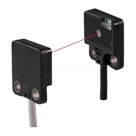
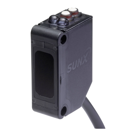
Long Range & Wide Area Photoelectric Sensor PX-2 SERIES
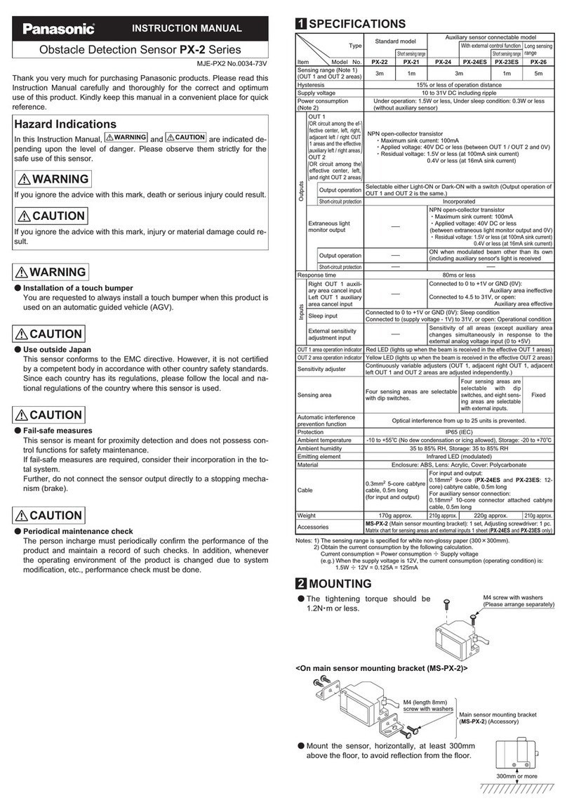
SPECIFICATIONS
Main sensors
Type Standard model Auxiliary sensor connectable model
With external control function Long sensing
range
Short sensing range Short sensing range
Item Model No. PX-22 PX-21 PX-24 PX-24ES PX-23ES PX-26
CE marking directive compliance
EMC Directive, RoHS Directive
Sensing range (OUT 1 and OUT 2 areas) (Note 2)
3 m 9.843 ft 1 m 3.281 ft 3 m 9.843 ft 1 m 3.281 ft 5 m 16.404 ft
Hysteresis (Note 2) 15 % or less of operation distance
Supply voltage 10 to 31 V DC including ripple
Power consumption (Note 3) Under operation: 1.5 W or less, Under sleep condition: 0.3 W or less (without auxiliary sensor)
OUT1
OUT2
NPN open-collector transistor
• Maximum sink current: 100 mA
• Applied voltage: 40 V DC or less (between OUT 1 / OUT 2 and 0 V)
• Residual voltage: 1.5 V or less (at 100 mA sink current)
0.4 V or less (at 16 mA sink current)
Utilization category DC-12 or DC-13
Output operation Selectable either Light-ON or Dark-ON with a switch (Output operation of OUT 1 and OUT 2 is the same.)
Short-circuit protection Incorporated
Extraneous light monitor
output
–
NPN open-collector transistor
• Maximum sink current: 100 mA
• Applied voltage: 40 V DC or less (between extraneous light monitor output and 0 V)
• Residual voltage: 1.5 V or less (at 100 mA sink current)
0.4 V or less (at 16 mA sink current)
Output operation
–
ON when modulated beam other than its own (including auxiliary sensor’s) light is received
Short-circuit protection
– –
Response time 80 ms or less
Operation
indicators
OUT 1 area Red LED (lights up when the beam is received in the effective OUT 1 areas)
OUT 2 area Yellow LED (lights up when the beam is received in the effective OUT 2 areas)
Sensitivity adjuster
Continuously variable adjusters (OUT 1, adjacent right OUT 1, adjacent left OUT 1 and OUT 2 areas are adjusted independently.)
External sensitivity adjustment function
–
Sensitivity adjustment is possible with an analog input.
Sensing area Four sensing areas are selectable with dip switches.
Four sensing areas are selectable with dip switches, and
eight sensing areas are selectable with external inputs.
Fixed
Sleep function Operating / sleep selectable with external input
Automatic interference prevention function
Optical interference from up to 25 units is prevented.
Environmental resistance
Pollution degree 3 (Industrial environment)
Protection IP65 (IEC)
Ambient temperature –10 to +55 °C +14 to +131 °F (No dew condensation or icing allowed), Storage: –20 to +70 °C –4 to +158 °F
Ambient humidity 35 to 85 % RH, Storage: 35 to 85 % RH
Ambient illuminance Incandescent light: 3,000 ℓx or less at the light-receiving face
Voltage withstandability 1,000 V AC for one min. between all supply terminals connected together and enclosure
Insulation resistance 20 MΩ, or more, with 500 V DC megger between all supply terminals connected together and enclosure
Vibration resistance 10 to 500 Hz frequency, 3 mm 0.118 in double amplitude (20 G max.) in X, Y and Z directions for two hours each
Shock resistance 500 m/s2acceleration (50 G approx.) in X, Y and Z directions three times each
Emitting element Infrared LED (Peak emission wavelength: 950 nm 0.037 mil, modulated)
Material Enclosure: ABS, Lens: Acrylic, Cover: Polycarbonate
Cable 0.3 mm25-core cabtyre cable, 0.5 m
1.640 ft long (for input and output)
For input and output: 0.18 mm29-core (PX-24ES and PX-23ES: 12-core) cabtyre cable, 0.5 m 1.640 ft long
For auxiliary sensor connection: 0.18 mm210-core connector attached cabtyre cable, 0.5 m 1.640 ft long
Cable extension Extension up to total 100 m 328.084 ft (10 m 32.808 ft for auxiliary sensor connection) is possible with 0.3 mm2, or more, cable.
Weight Net weight: 210 g approx.
Gross weight: 390 g approx.
Net weight: 220 g approx.
Gross weight: 400 g approx.
Net weight: 210 g approx.
Gross weight: 390 g approx.
Accessories
MS-PX-2 (Main sensor mounting bracket): 1 set, Adjusting screwdriver: 1 pc., Matrix chart for sensing areas and external inputs: 1 sheet (PX-24ES and PX-23ES only)
OR circuit among the effective center,
left, right, adjacent left / right OUT 1 areas
and the effective auxiliary left / right areas
OR circuit among the effective center, left
and right OUT 2 areas
Notes: 1) Where measurement conditions have not been specied precisely, the conditions used were an ambient temperature of +23 °C +73.4 °F.
2) The sensing range is specied for white non-glossy paper (300 × 300 mm 11.811 × 11.811 in) as the object.
3) Obtain the current consumption by the following calculation.
Current consumption = Power consumption ÷Supply voltage
(e.g.) When the supply voltage is 12 V, the current consumption (operating condition) is: 1.5 W ÷12 V = 0.125 A = 125 mA

