manuals.online logo
Brands
  1. Home
  2. •
  3. Brands
  4. •
  5. Panasonic
  6. •
  7. Accessories
  8. •
  9. Panasonic CY-111 Series User manual

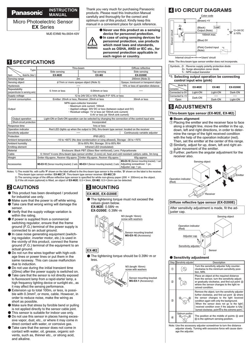
Panasonic CY-111 Series User manual

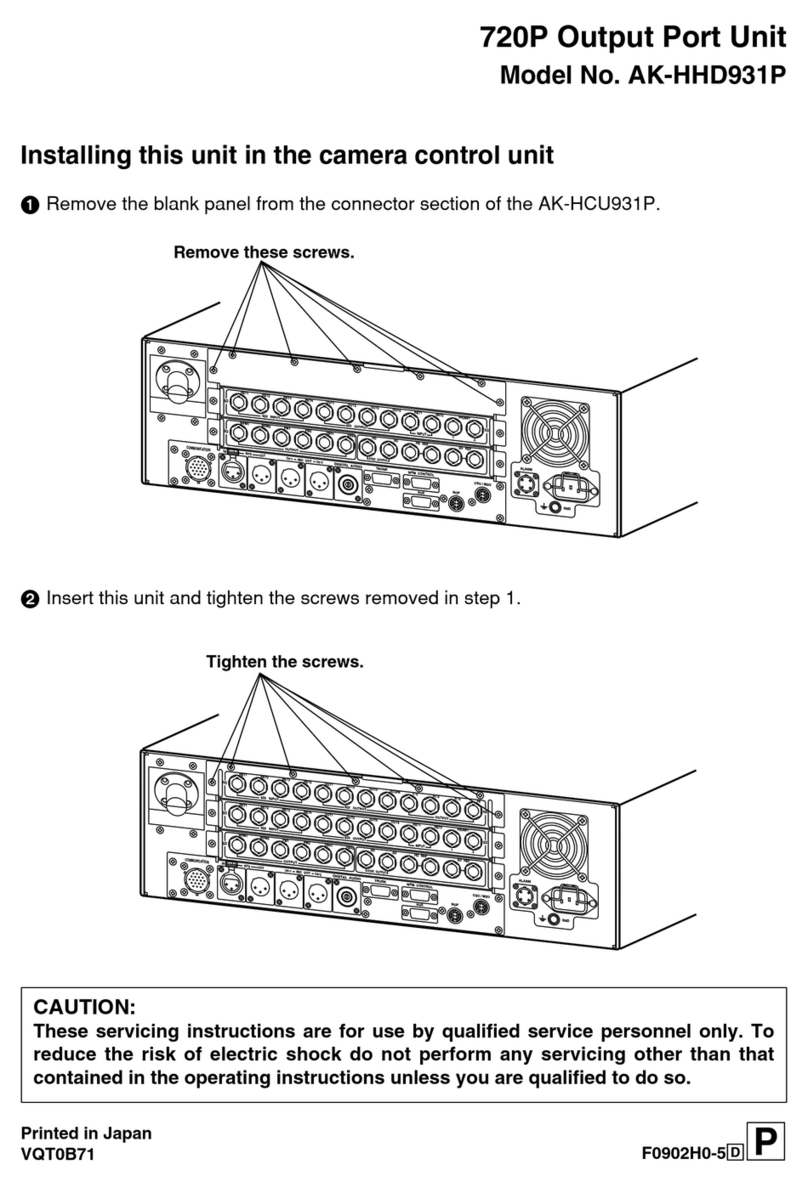
INSTRUCTIONS
Cylindrical Photoelectric Sensor
CY-111, CY-19q, CY-12qSeries
Thank you for purchasing products from Panasonic. Please read this
Instruction Manual carefully and thoroughly for the correct and optimum
use of this product. Kindly keep this manual in a convenient place for quick
reference.
WARNING
●Never use this product as a sensing device for personnel protection.
●In case of using sensing devices for personnel protection, use prod-
ucts which meet laws and standards, such as OSHA, ANSI or IEC
etc., for personnel protection applicable in each region or country.
1Cautions
●This product has been developed / produced for industrial use only.
●This product is suitable for indoor use only. The cable extension up to
a total of 10m or less with a strength of 0.34mm2or less (each emitter
and receiver of the thru-beam type) is possible.
●Make a cable length as short as possible to lessen noise pickup.
●Make sure that the power supply is off while wiring.
●Verify that the supply voltage including the ripple is within the rating.
●If power is supplied from a commercial switching regulator, ensure that
the frame ground (F.G.) terminal of the power supply is connected to
an actual ground.
●Shortcircuiting the load or wrong wiring may burn or damage the
product.
●Ensure that an isolation transformer is utilized for the DC power sup-
ply. If an autotransformer is utilized, the main body or power supply
may be damaged.
●If the used power supply generates a surge, connect a surge absorber
to the power supply to absorb the surge.
●Do not use the sensor during the initial transient time (0.5 sec) after
the power supply is switched on.
●Do not run the wires together with high-voltage lines or power lines
or put them in the same raceway. This can cause malfunction due to
induction.
● Avoid using the product where there are strong magnetic elds as they
may prevent the product from working according to the specication.
● Take care that the sensor is not directly exposed to a uorescent lamp
from a rapid-starter lamp or a high frequency lighting device, as it may
affect the sensing performance.
●Protect the sensor from water, oil, grease, organic solvents such as
thinner, etc., strong acid, and alkaline.
●Avoid using a product where there is excessive vapor, dust or cor-
rosive gases, or in a place where it could be exposed directly to water
or chemicals.
● This product cannot be used in an environment containing inam-
mable or explosive gases.
●Never disassemble or modify the product.
2Compliance with standards and directives
This product complies with the following standards and
regulations.
●For the EU: EMC Directive 2004/108/EC
●For the US and Canada:
ANSI/UL60947-5-2, CAN/CSA C22.2 No.14
●For Korea: S1-G-1-2009, S2-W-5-2009
* In case you require a UL listing mark or C-UL
listing mark, use a class 2 power supply unit.
RoHS directive
●This equipment complies with RoHS (CE and Chinese
directive).
3Sensor types
Cable type (2m) Connector type (M12)
Standard
Side view
4Part description
124
33
1Main body
2Mounting plate
3Nut
4Cable with connector
5Mounting
General installation hints
1. Attach the sensor directly on your equipment or use one of the optional
mounting brackets to x the sensor.
2. The tightening torque should be 3Nm or less.
3. If you mount a M12 connector type, you can use the optional cable with
the connector UZZ812qqD. The tightening torque for the connector part
should be 3Nm or less.
Mounting with the mounting bracket MS-CY1-1
1. Using the holes indicated
1, screw the mounting
bracket to the surface.
2. Feed the sensor into the
mounting hole 2and
afx it with the nuts on the
sensor.
1
2
Mounting with the mounting bracket MS-CY1-2
1. Using the holes indicated
1, screw the mounting
bracket to the surface.
2. Feed the sensor into the
mounting hole 2 and
adjust its direction.
3. Use the upper two screws
3to secure the sensor.
1
3
2
1
Model no. Description
MS-CY1-1 Material: Stainless steel
MS-CY1-2 Material: Plastic (recommended for a more exible beam axis
alignment)
6Mating cables
There are two types of mating cables: straight type and elbow type. You
only need mating cables for the connector type (M12).
Straight type Elbow type
Cable type Model no. Description
Straight UZZ81220D Length: 2m
UZZ81250D Length: 5m
Elbow UZZ81221D Length: 2m
UZZ81251D Length: 5m
7Reectors
Square form Hexagonal form
Reective tape
Reector form Model no. Description
Square RF-420 50 x 50mm
Hexagonal RF-410 24 x 21mm
Reective tape RF-40RL5 22 x 5m, thickness: 0.4mm
8Wiring diagrams
Emitter of thru-beam type



WR9'&

±%
9LROHW,QSXW
%OXH9
%URZQ9
Receiver of thru-beam / reective type (NPN)




±%
/RDG
WR9'&
%ODFN2XWSXW
%URZQ9
%OXH9
Receiver of thru-beam / reective type (PNP)




±'&%
/RDG
WR9
%URZQ9
%OXH9
%ODFNRXWSXW
9Terminal arrangement
M12 connector
12
43
Terminal no. Function
1+V
2Input (only emitter of thru-beam type)
30V
4Output (only receiver of thru-beam and reec-
tive type)
* Make sure to insulate the ends of all unused lead wires.
10 Detection curves
Thru-beam type
15
-15
15
15 m
10 m
cm
ø 12 mm
A
A = Sensing range
Diffuse reective type
5
1 5
cm
cm
10 cm
-1
1
A
1.4
-1.4
Object 10 x 10cm; 1= White 90%, 2= Gray 18%
2
Diffuse reective type with adjustable sensitivity
80
cm
cm
60 cm
1.4
-1.4
1
-1
A
Object 10 x 10cm; 1= White 90%, 2= Gray 18%
Retroreective type
4
4 m
10
-4
-10
A
m
4
2
cm
With reector RF-420
Retroreective type with polarizing lters
2
2 m
4
6
-2
-4
-6
m
A
3
2
cm
E/R
0.2
With reector RF-420
11 Dimensions
CY-1q
a
b
M18
Cable type Connector type
a (mm) b (mm) a (mm) b (mm)
Standard CY-
111q/121q/192q
46 28 60 28
Standard CY-191q48 28 62 28
Side view CY-
111Vq/121Vq/ 191Vq
/192Vq
62 28 76 28
Standard CY-122q62 44 76 44
Side view CY-122Vq78 44 92 44
Mounting bracket MS-CY1-1
35
28
50
15
20
1
20
10
==
==
ø18.22.5
6.5
16.5
6.5
Mounting bracket MS-CY1-2
10
45
==
25
55
2488
5
27
19.5
ø18.2
6.5
Reector RF-420
51
69
8
47
60
35
4 - R5
8
2 - ø
2 - ø 4.5
5.5
ø4.5
51.5
3.5
Reector RF-410
4
29
45
9
21
33
=
=
24
ø7.5
ø4.5
7.5
3
12 Specications
The connector type (M12) is also available for all models in the following table. To order, simply add “-Z” at the end of the order information.
Type Thru-beam (note 6) Retroreective Diffuse reective
With polarizing lters With sensitivity adjuster
Standard Side view Standard Side view Standard Side view Standard Side view Standard Side view
Model no. Light-ON CY-111AqCY-111VAqCY-192AqCY-192VAqCY-191AqCY-191VAqCY-121AqCY-121AqCY-122AqCY-122VAq
Dark-ONCY-111BqCY-111VBqCY-192BqCY-192VBqCY-191BqCY-191VBqCY-121BqCY-121VBqCY-122BqCY-122VBq
Sensing range 15m 4m (note 2) 2m (note 2) 100mm 600mm
Sensing object ≤ ø18mm, opaque object
(setting distance between
emitter and receiver: 15m)
≤ ø50mm, opaque,
translucent or transparent
object (note 2, 4)
≤ ø50mm, opaque,
translucent, transparent or
specular object (note 2, 4)
Opaque, translucent or transparent object (note 4)
Hysteresis — 3 to 15% operating distance (note 3)
Supply voltage 12 to 24V DC % (+10% / -10%), ripple ≤ P-P10%
Current consumption Emitter: ≤ 35mA
Receiver: ≤ 35mA
≤ 35 mA
Output NPN open-collector transistor
●Maximum sink current: 100mA
● Applied voltage: ≤ 24 V DC or less between sensing output and 0V
● Residual voltage: ≤ 1.5V at maximum sink current
PNP open-collector transistor
● Maximum source current: ≤ 100 mA
● Applied voltage: ≤ 24V DC (output and +V)
● Residual voltage: ≤ 1.5V at maximum source current
Short-circuit protection Incorporated
Response time ≤ 1ms
Test input function Incorporated —
Operation indicator Yellow LED lights up when the output is ON; incorporated on the receiver for thru-beam type
Power indicator Green LED lights up —
Pollution degree 3 (Industrial environment)
Protection IP67 (IEC)
Ambient temperature -25 to +55°C (no dew condensation or icing allowed), Storage: -40 – +70°C
Ambient humidity 50% RH (at +70°C)
Ambient illuminance Incandescent light: 5,000ℓx at the light receiving face
EMC EN 60947-5-2
Voltage withstandability 500V AC
Vibration resistance 10 to 55 Hz frequency, 0.5 mm amplitude in X, Y and Z directions for three times each
Shock resistance 294 m/s2acceleration in X, Y and Z directions for three times each
Emitting element Infrared LED Red LED Infrared LED
Peak emission wavelength 890 nm 875 nm 665 nm 875 nm
Material Enclosure: PBT, Lens: PMMA
Cable (except for connec-
tor type)
0.44 mm23-core cab tire cable
Cable extension Extension up to total 10 m is possible with 0.34 mm2cable
Net weight
(note 5)
Cable type ≈65g ≈70g ≈65g ≈70g ≈65g ≈70g ≈65g ≈70g ≈75g
Connector
type
≈15g ≈20g. ≈15g ≈20g ≈15g ≈20g ≈15g ≈20g ≈25g
Accessories Nut: 4 pcs. Nut: 2 pcs.
1. Where measurement conditions have not been specied precisely, the conditions used were an ambient temperature of +23°C.
2. The sensing range and the sensing object of the retroreective type sensor are specied for the RF-420 reector (optional).
3. The sensing range and the hysteresis of the diffuse reective type sensor are specied for white non-glossy paper (200 x 200mm) as sample object.
4. Make sure to conrm the detection for the transparent and translucent object with an actual sensor before use.
5. The weight includes the weight of the nuts.
6. The model No. with “E” shown on the label afxed to the thru-beam type sensor is the emitter, “D” shown on the label is the receiver, (e.g.) emitter of CY-111A: CY-111E,
receiver of CY-111A: CY-111AD.
4

This manual suits for next models

2

Other Panasonic Accessories manuals

Panasonic Light Emitting Diodes LNJ253W82RA User manual

Panasonic

Panasonic Light Emitting Diodes LNJ253W82RA User manual

Panasonic KX-HNS104 User manual

Panasonic

Panasonic KX-HNS104 User manual

Panasonic MA3S1370G User manual

Panasonic

Panasonic MA3S1370G User manual

Panasonic MA27P06 User manual

Panasonic

Panasonic MA27P06 User manual

Panasonic AW-PB306 User manual

Panasonic

Panasonic AW-PB306 User manual

Panasonic MA3J702 User manual

Panasonic

Panasonic MA3J702 User manual

Panasonic KX-HNA101 User manual

Panasonic

Panasonic KX-HNA101 User manual

Panasonic Switching Diodes MA4X174 (MA174) User manual

Panasonic

Panasonic Switching Diodes MA4X174 (MA174) User manual

Panasonic Digital Fiber Sensor FX-301 User manual

Panasonic

Panasonic Digital Fiber Sensor FX-301 User manual

Panasonic HG-C Series User manual

Panasonic

Panasonic HG-C Series User manual

Panasonic MA3D750 User manual

Panasonic

Panasonic MA3D750 User manual

Panasonic Schottky Barrier Diodes MA4ZD030G User manual

Panasonic

Panasonic Schottky Barrier Diodes MA4ZD030G User manual

Panasonic GX-M Series User manual

Panasonic

Panasonic GX-M Series User manual

Panasonic EX-10 Series User manual

Panasonic

Panasonic EX-10 Series User manual

Panasonic HG-T1110 User manual

Panasonic

Panasonic HG-T1110 User manual

Panasonic MA27D30 User manual

Panasonic

Panasonic MA27D30 User manual

Panasonic KX-HNS102HM User manual

Panasonic

Panasonic KX-HNS102HM User manual

Panasonic MA2SP06 User manual

Panasonic

Panasonic MA2SP06 User manual

Panasonic WV-PB5508 User manual

Panasonic

Panasonic WV-PB5508 User manual

Panasonic MCO-230AIC User manual

Panasonic

Panasonic MCO-230AIC User manual

Panasonic WJ-HDE500 User manual

Panasonic

Panasonic WJ-HDE500 User manual

Panasonic TK712SSQP User manual

Panasonic

Panasonic TK712SSQP User manual

Panasonic MA5J002E User manual

Panasonic

Panasonic MA5J002E User manual

Panasonic FX-100 Series User manual

Panasonic

Panasonic FX-100 Series User manual

Popular Accessories manuals by other brands

PASCO PASPort PS-2120 quick start guide

PASCO

PASCO PASPort PS-2120 quick start guide

POLTI SANI SYSTEM manual

POLTI

POLTI SANI SYSTEM manual

SICK LMS4000 operating instructions

SICK

SICK LMS4000 operating instructions

Beckhoff CX2500-0070 manual

Beckhoff

Beckhoff CX2500-0070 manual

Lippert Components Solera Slide Topper Installation and owner's manual

Lippert Components

Lippert Components Solera Slide Topper Installation and owner's manual

WDT DUFTDOS-AK1 operating instructions

WDT

WDT DUFTDOS-AK1 operating instructions

Foerster CORCOGRAPH Ro 20 P operating instructions

Foerster

Foerster CORCOGRAPH Ro 20 P operating instructions

dymax UVCS user guide

dymax

dymax UVCS user guide

Foscam 305503000664 user manual

Foscam

Foscam 305503000664 user manual

Varec 2500 Installation and operation manual

Varec

Varec 2500 Installation and operation manual

METER TEROS 11 Integrator guide

METER

METER TEROS 11 Integrator guide

E+E Elektronik EE850 user manual

E+E Elektronik

E+E Elektronik EE850 user manual

RDI Prestige K10 Instructions for use

RDI

RDI Prestige K10 Instructions for use

Avery Weigh-Tronix 640XL manual

Avery Weigh-Tronix

Avery Weigh-Tronix 640XL manual

iOptron ZEQ25 Instruction

iOptron

iOptron ZEQ25 Instruction

Medisana 60230 instruction manual

Medisana

Medisana 60230 instruction manual

OpenTag OpenTag3 manual

OpenTag

OpenTag OpenTag3 manual

Minoston MP23W quick guide

Minoston

Minoston MP23W quick guide

manuals.online logo
manuals.online logoBrands
  • About & Mission
  • Contact us
  • Privacy Policy
  • Terms and Conditions

Copyright 2025 Manuals.Online. All Rights Reserved.