Panasonic Strada CY-RC50KU User manual

Universal Rear-View Camera
Model
CY-RC50KU
Operating Instructions
OPlease read these instructions (including “Limited Warranty” and “Customer
Services Directory”) carefully before using this product and keep this manual for
future reference.
POWER
CAMERA
IN
VIDEO
OUT
English

RRead the operating instructions for the
unit and all other components of your car
navigation system carefully before using
the system. They contain instructions
about how to use the system in a safe and
effective manner. Panasonic assumes no
responsibility for any problems resulting
from failure to observe the instructions
given in this manual.
This pictograph alerts you
to the presence of important
operating instructions.
Failure to heed the
instructions may result in
severe injury or death.
Warning
This pictograph alerts you
to the presence of important
operating instructions. Failure
to heed the instructions may
result in injury or material
damage.
Caution
Observe the following warnings
when using this unit.
RAlways reverse slowly, checking for safety
with your own eyes.
The camera image is perceived differently from
the actual distance. The field of view which can
be displayed is also limited. Reverse slowly,
checking safety by eye, rather than relying on
the screen. Reversing without checking safety
can cause collisions with people and objects.
RAlways use a fuse of the specified capacity.
Ask a specialist engineer to replace the fuse.
If the fuse used exceeds the specified capacity,
it can cause fire, smoke, ignition and other
breakdowns. Consult your dealer or service
center to request fuse replacement or repair.
RDo not continue using the system when it has
broken down or malfunctioned.
If there is a breakdown (no image, no sound,
etc.) or malfunctions (a foreign object inside,
water on the components, smoke comes out,
abnormal noise or odor, etc.), immediately
stop using it, then consult your dealer or
service center. Continued use in that state
could cause fire, electric shock or accident.
Warning
RThis manual uses pictographs to show you
how to use the product safely and to alert
you to potential dangers resulting from
improper connections and operations.
The meanings of the pictographs are
explained below. It is important that you
fully understand the meanings of the
pictographs in order to use this manual
and the system properly.
Safety information

Observe the following cautions
when using this unit.
RDo not use this system for any purpose other
than mounting on a road vehicle.
Non-vehicular use (such as use outdoors
or on a pleasure boat) could cause smoking
generation, ignition, electric shock, injury and
breakdown.
RDo not use an automatic car–washing
machine to wash the vehicle.
Exposure to water from a high pressure hose
or impact from a brush may cause the system
to fall resulting in accident or injury. Water
entering inside the camera can result in a fire,
electric shock or breakdown.
Observe the following cautions
when installing.
RDo not damage cords.
Do not damage, pull, bend, twist or modify
cords, place heavy objects on them, or place
them near hot equipment or in contact with
hot parts of the vehicle. Breaking or shorting
cords could cause fire, electric shock, or
accidents.
ORoute cords so that they cannot be pinched
by the body of the vehicle, screws or
moving parts (seat rails etc.).
ODo not press cords with the point of a
screwdriver or similar implement.
Caution
RDo not damage the rear view camera cord.
Water and moisture can move along the cord
from the damaged area and enter the camera,
causing fire, electric shock and breakdown.
RRoute the rear view camera cord inside
the vehicle, so that water cannot penetrate
them.
If water enters the vehicle during rain or car
washing, it could cause fire or electric shock.
ROrder wiring, mounting and dismounting
work from a specialist engineer.
Wiring, mounting and dismounting work
requires specialist skills and experience. For
safety, ask your dealer to perform such work.
In the case that this system is installed in a
vehicle with a drive computer or a navigation
system, improper removal of the battery may
result in erasure of system’s memory.
ROnly use the accessories provided and the
parts specified.
Use of non-specified parts can cause internal
damage to the equipment, and insecure
mounting could allow it to fall off, causing
accident, breakdown and fire.
RMount the equipment securely, so that it
cannot come off and fall.
Wipe the mounting area clean of dirt, wax
etc., then fasten the camera securely in place.
Re-affixing adhesive parts or use of general-
purpose double-sided tape could cause weak
bonding that would allow the equipment to
drop off while the vehicle is in motion, causing
accident or injury. Check the state of bonding
or mounting (loose screws etc.) occasionally.

If you suspect something wrong
Check and take steps as described below.
If the described suggestions do not solve the problem, it is recommended to take the unit
to your nearest authorized Panasonic Servicenter. The product should be serviced only by
qualified personnel. Please refer checking and repair to professionals.
Panasonic shall not be liable for any accidents arising out of neglect of checking the unit or
your own repair after your checking.
Never take measures especially those other than indicated by italic letters in “Possible
solution” described below because those are too dangerous for users to handle
themselves.
Warning
ODo not use the unit in an irregular condition, for example, without sound, or with smoke
or a foul smell, which can cause ignition or electric shock. Immediately stop using the
unit and consult your dealer.
ONever try to repair the unit by yourself because it is dangerous to do so.
Problem Possible cause °Possible solution
No image from the
camera.
OIncorrect settings or connection.
°Check settings and cord connections.
OThe fuse for the system, or for equipment connected to it, has
blown.
°Consult a Panasonic Servicenter.
Image is unclear. OIs there dust or dirt on the camera?
°Wipe the lens clean.
White lines (vertical
lines of light) on the
screen.
OIf the camera is viewing the sun directly, or a strong light
(reflection from a fender, a headlight beam etc.) shines into it,
bright vertical lines can appear above and below the light source.
(Smearing)
°This is not a breakdown.
Noise on the
screen.
OWhen the area viewed by the camera is lit by fluorescent light or
a similar light source, noise can appear on the screen. (Flickering)
°This is not a breakdown.
Screen display is
hard to see.
OThe screen display may become hard to see when it shows a
dark area, or an image that is bright in a small area, or when the
camera is hot.
°This is not a breakdown.
Troubleshooting

CANADA
WARRANTY SERVICE
FOR PRODUCT OPERATION ASSISTANCE, please
contact:
Our Customer Care Centre:
Telephone #: (905) 624-5505
1-800 #: 1-800-561-5505
Fax #: (905) 238-2360
Email link: “Contact Us” on www.panasonic.ca
FOR PRODUCT REPAIRS, please locate your nearest
Authorized Servicentre at www.panasonic.ca:
Link : “Servicentres™ locator” under “Customer
support”
IF YOU SHIP THE PRODUCT TO A SERVICENTRE
Carefully pack and send prepaid, adequately
insured and preferably in the original carton.
Include details of the defect claimed, and proof of
date of original purchase.
U.S.A.
Obtain Product Information and Operating
Assistance;
locate your nearest Dealer or Servicenter; purchase
Parts and Accessories; or make Customer Service
and Literature requests by visiting our Web Site at:
http://www.panasonic.com/support
or, contact us via the web at:
http://www.panasonic.com/contactinfo
You may also contact us directly at:
1-800-211-PANA (7262),
Monday-Friday 9 am-9 pm; Saturday-Sunday 10
am-7 pm, EST.
For hearing or speech impaired TTY users,
TTY : 1-877-833-8855
Accessory Purchases:
Purchase Parts, Accessories and Instruction Books
online for all Panasonic Products by visiting our
Web Site at:
http://www.pasc.panasonic.com
or, send your request by E-mail to:
You may also contact us directly at:
1-800-332-5368 (Phone) 1-800-237-9080 (Fax
Only)
(Monday-Friday 9 am to 8 pm, EST.)
Panasonic Services Company
20421 84th Avenue South, Kent, WA 98032
(We accept Visa, MasterCard, Discover Card,
American Express, and Personal Checks)
Service in Puerto Rico
Panasonic Puerto Rico, Inc.
Panasonic Sales Company
Factory Servicenter:
Ave. 65 de Infantería, Km. 9.5, San Gabriel
Industrial Park,
Carolina, Puerto Rico 00985
Phone (787) 750-4300, Fax (787) 768-2910
For hearing or speech impaired TTY users,
TTY : 1-866-605-1277
Customer services directory

© 2007 Matsushita Electric Industrial Co., Ltd. All Rights Reserved.
Panasonic Consumer
Electronics Company,
Division of Panasonic
Corporation of North America
One Panasonic Way, Secaucus,
New Jersey 07094
http://www.panasonic.com
Panasonic Sales Company,
Division of Panasonic Puerto
Rico, Inc. (“PSC”)
Ave. 65 de Infanteria, Km. 9.5
San Gabriel Industrial Park,
Carolina, Puerto Rico 00985
http://www.panasonic.com
Panasonic Canada Inc.
5770 Ambler Drive,
Mississauga, Ontario
L4W 2T3
http://www.panasonic.ca
Output image ...........................................Wide-angle mirror image (for checking the rear view)
Video format .....................................................................................................NTSC composite
Power supply ......................................................................................DC 12 V, negative ground
Power consumption..............................................................................1.6 W (approx. 135 mA)
Image sensor .................................................................... Color CCD, solid-state, 6.35 mm {1
/
4"}
Effective pixels ........................................................................................Approx. 250 000 pixels
Lens....................................................................... Wide angle, focal length f=1.94 mm, F 1:2.8
Angular field of view .................................................................. Horizontal: 134°, Vertical: 103°
S/N ratio................................................................. 46 dB or more (at recommended light level)
Horizontal resolution.............................................................................. 330 TV lines (at center)
Brightness range...............................................................................Approx. 1.5 lx – 100 000 lx
Image output.........................................................................................................1 Vp-p (75 Ω)
Dimensions (W x H x D)
ORear view camera.............................................23 mm x 21 mm x 20 mm {15
/
16" x 7
/
8" x 13
/
16"}
(cord length 4 m, not including projections on the rear)
ORear view camera control unit....................... 76 mm x 27 mm x 40 mm {3" x 1
1
/
16" x 1
9
/
16"}
Weight
ORear view camera................................................... Approx. 90
g
{3.2 oz.} (including cord)
ORear view camera control unit.........................................................Approx. 110
g
{3.9 oz.}
Note:
OSpecifications and the design are subject to modification without notice due to
improvements in technology.
OSome figures and illustrations on this manual may be different from your product.
Printed in JapanYEFM285995 F0207-0
Specifications

Observe the following warnings
when installing.
RUse on a DC 12 V grounded vehicle.
This system can only be used on a DC 12 V
grounded vehicle. It cannot be used in DC 24 V
and other battery system (large trucks, diesel
vehicles for use in cold regions, etc.). Use on
such vehicles would cause fire and breakdown.
RDisconnect the battery terminal during
performing any wiring or installation work.
Wiring or installation work with the battery
terminal connected could cause electric shock
and injury from shorting.
RThis system should be installed in a way so
that operation of vehicle protective devices
such as an air bag is not hindered.
Should this system be installed in a vehicle
with a protective device such as an air bag
or an anti-theft system, check with the car
manufacturer about operational cautions
prior to attempting installation and perform
the installation in a safe and proper manner.
Improper removal of the battery may result in
a malfunction of a device or possibly death.
RNever use the security parts of the vehicle
for mounting or grounding the system.
Use of the bolts or nuts of security parts
(steering, brake systems, fuel tank etc.) can
cause brake failure, fire, or other accidents.
RCheck positions of pipes, tanks, electric
wirings in the vehicle when mounting.
Never interfere with or touch pipes, tanks,
or electric wirings when opening holes in
the vehicle body for installation. Apply rust
prevention and waterproofing treatments to
the processed area, as rust or water leakage
may result in a fire, an electric shock, or other
accident.
RRoute cords so that they do not get in the
way of occupants driving or getting into or
out of the vehicle.
Route cords so that they do not tangle with the
steering wheel, shift lever, brake pedals, feet
etc., and bundle and fasten them appropriately.
Poorly arranged cords can cause accident and
injury.
RWire and mount the system as instructed.
Fire or accident could result if wiring and
mounting do not properly follow the operating
instructions.
RDo not attempt to disassemble, repair or
modify the system.
Never attempt to disassemble, repair or modify
the system, or to remove cord insulation to
take power supply from other devices. Fire,
electric shock or accident could result.
RAfter mounting and wiring the system, check
that all vehicle systems function normally.
If any vehicle equipment (brakes, lights, horn,
hazard and indicator lights etc.) does not work
normally, fire, electric shock or accident could
result.
RKeep screws and other small components
away from small children.
There is a risk that they could swallow
small components. Seek immediate medical
attention if that happens.
Warning

Carefully read the instruction manuals for the connected devices (Car
Monitor etc.).
Before reversing, always check behind you by eye.
OThis product uses mirrored display (which mimics the orientation of the rear-view and side
mirrors), and is for checking the view behind the vehicle.
OIt is intended to augment the driver’s field of vision behind the vehicle. It is not able to view
all hazards and obstacles.
OIt uses a wide-angle lens, which makes close areas appear wider and further areas narrower.
This may cause perceived distances to differ from actual distances.
This product can be connected to a monitor etc. with RCA-type video inputs. When the
shift lever is in reverse (R), the linkage function (camera interrupt display) and scaled
display correspond to the connected display device, so we are unable to guarantee normal
operation.
Check the mounting of the system components regularly
OCheck that there are no loose screws, and that the camera bracket is not detached.
OCheck that the rubber water seals where the cord enters the vehicle are parallel to the rubber
gasket where they are in contact.
Do not display a direct view of the sun for long periods
OA burned image could remain on the screen.
Do not use a cellular telephone or wireless equipment close
to the system
OScreen noise and malfunctions could result.
You are advised to use cellular telephone or wireless equipment away from this system.
Disclaimers
OAny repairs to breakdowns or damage caused by fire, earthquake, third-party action, other
accident, actions of the user, whether by accident or design, incorrect operation or usage
under other abnormal conditions will, as a rule, require payment of repair fees.
ONot guaranteed when equipped in a commercial-use vehicle (buses, trucks, taxis, goods
vehicles etc.).
Notes on use

Pesticide
Alcohol
Thinner
Benzine
Wax
Caution on cleaning
ODo not wipe with volatile chemicals, such as alcohol, benzine, thinners and gasoline. These
can cause deformation, deterioration and breakage.
ODo not wipe with cleaners that contain abrasive particles, as they leave scratches.
OIf the lens is dirty, wipe it gently with a soft, moist cloth. Wiping strongly with a dry cloth
will damage the lens.
Product servicing
If the suggestions in the charts do not solve the problem, we recommend that you take it to
your nearest authorized Panasonic Servicenter. The product should be serviced only by a
qualified technician.
Replacing the Fuse
Use fuses of the same specified rating (1 A). Using different substitutes or fuses with higher
rating, or connecting the product directly without a fuse, could cause fire or damage to this
unit.
If the replacement of the fuse fails, consult your nearest authorized Panasonic Servicenter
for service.
Maintenance

U.S.A.
PANASONIC CONSUMER ELECTRONICS COMPANY,
DIVISION OF PANASONIC CORPORATION OF NORTH AMERICA
One Panasonic Way, Secaucus, New Jersey 07094
PANASONIC SALES COMPANY,
DIVISION OF PANASONIC PUERTO RICO, INC.
Ave. 65 de infanteria, Km. 9.5, San Gabriel Industrial Park
Carolina, Puerto Rico 00985
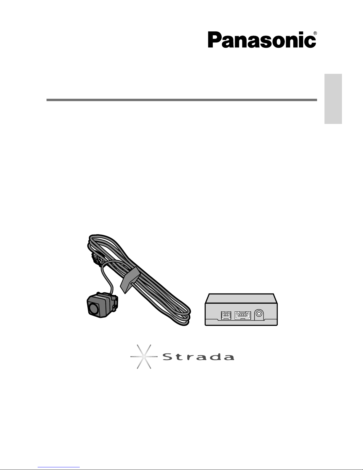
PANASONIC AUTO PRODUCTS
LIMITED WARRANTY
LIMITED WARRANTY COVERAGE
If your product does not work properly because of defects in materials and
workmanship.
Panasonic Consumer Electronics Company or Panasonic Sales Company
(collectively referred to as “the warrantor”) will, for the length of the period
indicated in the chart below, which starts with the date of original purchase
(“warranty period”), at its option either (a) repair your product with new or
refurbished parts, or (b) replace it with a new or refurbished product. The
decision to repair or replace will be made by the warrantor.
Categories Parts Labor
Audio Components (except items listed below) One (1) Year One (1) Year
MXE Series Audio Components (except items listed below) Two (2) Years Two (2) Years
Speakers
Defective Car Audio Speakers under warranty must be
exchanged at the place of purchase. Contact your Dealer
for details.
One (1) Year Not Applicable
Accessories (in exchange for defective items) Ninety (90) Days Not Applicable
During the “Labor” warranty period, there will be no charge for labor. During
the “Parts” warranty period, there will be no charge for parts. You must carry in
or mail in your product prepaid during the warranty period. If nonrechargeable
batteries are included, they are not warranted. This warranty only applies to
products purchased and serviced in the United States or Puerto Rico. This
warranty is extended only to the original purchaser of a new product which was
not sold “as is”. A purchase receipt or other proof of the original purchase date
is required for warranty service.
CARRY-IN OR MAIL-IN SERVICE
For Carry-In or Mail-In Service in the United States, call 1-800-211-PANA (7262)
or visit
Panasonic Web Site: http://www.panasonic.com
For assistance in Puerto Rico, call Panasonic Sales Company (787)-750- 4300
or fax (787)-768-2910.
LIMITED WARRANTY LIMITS AND EXCLUSIONS
This warranty ONLY COVERS failures due to defects in materials and
workmanship, and DOES NOT COVER normal wear and tear or cosmetic
damage. The warranty ALSO DOES NOT COVER damages which occurred
during shipment, failures which are caused by products not supplied by the
warrantor, failures which result from accident, misuse, abuse, neglect, bug
infestation, mishandling, misapplication, alteration, faulty installation, set-
up adjustment, maladjustment of consumer control, improper maintenance,
improper antenna, inadequate signal reception or pickup, power line surge,
improper voltage supply, lightning, modification, commercial use (such as
use in hotels, offices, restaurants, or other business uses) or rental use of
the product, or service by anyone other than the technician from Factory
Servicenter or other authorized service centers, or damage that is attributable to
acts of God.
THERE ARE NO EXPRESS WARRANTIES EXCEPT AS LISTED UNDER
“LIMITED WARRANTY COVERAGE”. THE WARRANTOR IS NOT LIABLE FOR
INCIDENTAL OR CONSEQUENTIAL DAMAGES RESULTING FROM THE USE OF
THIS PRODUCT, OR ARISING OUT OF ANY BREACH OF THIS WARRANTY. (As
examples, this excludes damages for lost time, cost of having someone remove
or re-install an installed unit if applicable, travel to and from the sevicer, and loss
of media, data or other memory contents. The items listed are not exclusive,
but are for illustration only.) ALL EXPRESS AND IMPLIED WARRANTIES,
INCLUDING THE WARRANTY OF MERCHANTABILITY, ARE LIMITED TO THE
PERIOD OF THE LIMITED WARRANTY.
Some states do not allow the exclusion or limitation of incidental or
consequential damages, or limitations on how long an implied warranty lasts,
so the exclusions may not apply to you.
This warranty gives you specific legal rights and you may also have other rights
which vary from state to state. If a problem with this product develops during
or after the warranty period, you may contact your dealer or Servicenter. If the
problem is not handled to your satisfaction, then write to warrantor’s Consumer
Affairs Department at the addresses of the warrantor.
PARTS AND SERVICE WHICH ARE NOT COVERED BY THIS LIMITED
WARRANTY ARE YOUR RESPONSIBILITY.
Customer’s Record
Model
No.
Serial
No.
Dealer’s
No.
Code
No.
Dealer’s
Address
Date of
Purchase
CANADA
Panasonic Canada Inc.
5770 Ambler Drive, Mississauga Ontario L4W 2T3
PANASONIC PRODUCT LIMITED WARRANTY
Panasonic Canada Inc. warrants this product to be free from defects in materials
and workmanship and agrees to remedy any such defect for a period as stated
below from the date of original purchase.
CAR AUDIO PRODUCT – ONE (1) YEAR, PARTS AND LABOUR
(The labour to install or remove the product is not warranted)
ACCESSOIRES - NINETY (90) DAYS, (IN EXCHANGE FOR DEFECTIVE ITEMS)
LIMITATIONS AND EXCLUSIONS
This warranty does not apply to products purchased outside Canada or to any
product which has been improperly installed, subjected to usage for which
the product was not designed, misused or abused, damaged during shipping,
or which has been altered or repaired in any way that affects the reliability or
detracts from the performance, nor does it cover any product which is used
commercially. Dry cell batteries are also excluded from coverage under this
warranty.
This warranty is extended to the original end user purchaser only. A purchase
receipt or other proof of the original purchase date is required before warranty
service is performed.
THIS EXPRESS, LIMITED WARRANTY IS IN LIEU OF ALL OTHER
WARRANTIES, EXPRESS OR IMPLIED, INCLUDING ANY IMPLIED
WARRANTIES OF MERCHANTABILITY AND FITNESS FOR A PARTICULAR
PURPOSE.
IN NO EVENT WILL PANASONIC CANADA INC. BE LIABLE FOR ANY SPECIAL,
INDIRECT OR CONSEQUENTIAL DAMAGES.
In certain instances, some jurisdictions do not allow the exclusion or limitation
of incidental or consequential damages, or the exclusion of implied warranties,
so the above limitations and exclusions may not be applicable.
Limited warranty

Consult your dealer if any item is missing.
OFigures in ( ) are quantities.
Rear view camera
control unit
(1)
Power cord
(2)
RCA cord
(1)
QAccessories
Operating instructions
(this manual)
(1)
Owners information
card
(1)
Camera bracket
(1)
Cord rail
Rear view camera
(with Rubber water seal)
4 m cord
Bolts with washer
(1)
Hexagon wrench
M3 × 6 mm
Velcro tape
(4) (1)38 × 70 mm
(1) (1)
Tie band
(2)
Cord clamp
18 cm
Double-sided tape
(7)
(1)30 × 70 mm
Clip connector
(1)6 m5 m
Check the contents

ORoute the camera cord so that it does not allow rainwater etc. to penetrate.
OAllow enough slack in the cord so that it is not pulled when the door is opened and closed.
Rear view camera
Rear view camera
control unit
Cord clamp
Harness cover
Route the cord above the back door
(outside).
Do not route the cord under the back
door (inside).
Fasten with cord clamps at
key points, then bring the
cord in where the clearance
from the edge of the door
is wider.
The cord will be damaged if
pinched by the edge of the
back door.
Car navigation etc.
Cord rail
(peel off backing paper)
Cut to the appropriate size.
Rear view camera cord
Rubber water seal
(Attached to rear
view camera.)
Place against the rubber
gasket and bring the
cord into the interior.
Cord clamp
Hatchback or Van type
Tie band
Tie to the harness cover.
Cord routing (example)

Note:
OOpen and close the back door or trunk lid slowly to check that the camera cord is not
pinched or abraded by the door/lid. Moisture or water can enter through the damaged area
of the cord and penetrate to the interior of the camera, causing breakdowns.
ORoute the camera cord as far as possible from the antenna cord.
(It could cause noise in TV and radio signals.)
OIf AM radio broadcasts are affected by noise, move the camera cord further from the vehicle
wiring harness.
Rear view camera
Trunk lidCord clamp
Rubber gasket
Rubber water seal
(Attached to rear view camera.)
View with trunk lid closed
Rubber water seal
(Attached to rear view camera.)
Rubber gasket
Attach the rubber water seal so that it is parallel with
the rubber gasket when the trunk is closed.
Sedan type

Note:
OThe camera cannot be affixed to painted or glass surfaces which have been treated
with fluoroplastics (treatments which shed water droplets, mud etc.), or to re-painted
surfaces.
Make connections and placement tentatively at first, to check positions. Repeated
affixing weakens the adhesive.
OThe screw holes to use, and the possible angle adjustment, vary according to the
mounting position. Adjust the angle and check that the required field of view is
visible. (It is not possible to re-affix components.)
OMount the camera so that it does not contact the vehicle body or rear wipers.
QFor secure mounting
ODo not work outdoors in rainy weather.
OWhen the air temperature is low, use the vehicle’s interior heater or defogger, or a
dryer, to warm the bonding area.
OUse a dryer etc. to thoroughly remove all moisture. Dirt and moisture on the bonding
surface reduce bond strength and could cause the camera to fall off.
OAfter mounting the camera, do not expose it to rain or other water, pull it or subject it
to strong forces for 24 hours.
Rear view camera
Wipe away all oil and dirt etc. from the mounting surface.
Before mounting
Mounting procedure

Wipe away all oil and dirt etc. from the mounting surface.
Note:
Do not mount the control unit in the following locations, which could cause breakdowns.
OPlaces exposed to water
OPlaces which could be stepped on
ODusty places
OClose to heater ducts or heat-emitting objects
OPlaces exposed to direct sunlight
OUnder the carpet, or any other position that gets hot
Before mounting
Rear view camera control unit Rear view camera control unit
Velcro tape Double-sided tape
Rear view camera control unit
Mounting on carpet etc. Mounting on hard surfaces (floor
etc.)

REVERSE
GND
1 A
POWER
CAMERA
IN
VIDEO
OUT
Camera input (CAMERA IN)
Video output (VIDEO OUT)
When connected to a Panasonic Car Monitor etc., the image from the camera is automatically
displayed in the screen when the shift lever is moved to reverse (R).
OFor some combinations of vehicle type and device, additional cords (option) may be
required, or connection may not be possible.
Consult your dealer or service center.
OFor connection with products from other companies, consult the manufacturer of each
device.
Note:
OInsert connectors securely. Also, take care to avoid pulling on the cords.
ODo not extend the RCA cord or rear view camera cord, as video noise and breakdowns could
result.
OOnly use clip connectors in the specified places.
Always wear gloves for safety during
wiring and mounting operations.
QInstallation procedure
Disconnect the battery terminal.
Make wiring connections.
OTo avoid short circuit accidents, do not
connect the power cord connectors until all
wiring is complete.
Mount the components.
Reconnect the battery terminal.
Make connections and set and operate acc
o
Rear view camera
control unit
Power cord
(5 m)
RCA cord
(6 m)
Rear view camera
(4 m)
Ground lead
(Black)
Fuse 1 A
Reverse lead
(Violet/white stripe)
(Yellow)
To camera image input terminal or video
input terminal
To a metal part of the vehicle body
To the wire of the reverse lamp
(Yellow)
Connect to an area of exposed metal, not
covered with paint etc.
Do not connect to a point that has a
constant power supply.
Power connector (POWER)
NTSC Only
Wiring procedure

o
rding to the installation instructions for the connected devices.
P
R
N
D
2
L
1A
+ −
Clip connector
(supplied with
CN-NVD905U)
Reverse lead
(Violet/white stripe)
Ground lead
(Black)
Battery
Car chassis
Rear view camera
(4 m)
RCA cord
(6 m)
(Yellow)
(Yellow)
Car Navigation System
(CN-NVD905U: option)
Rear view camera – RCA conversion cable
(supplied with CN-NVD905U)
Clip connector
Cut off the end terminal
and connect to the clip
connector.
P
R
N
D
2
L
1A
+ −
CAMERA-IN
Reverse lead
(Violet/white stripe)
In-Dash Monitor
(CQ-VD7005U: option)
Camera input terminal
Reverse extension cord
(Violet/white stripe)
Reverse lead
(Violet/white stripe)
Reverse lamp
Transmission
Rear view camera
control unit
Clip connector
Connection to a Car Navigation System (example)
Connection to a Car Monitor (example)
Clip connector
Transmission
Reverse lead
(Violet/white stripe)
Ground lead
(Black)
Battery
Car chassis
Rear view camera
control unit
Rear view camera
(4 m)
(Yellow)
(Yellow)
RCA cord
(6 m)
Reverse lamp
Connect to the wire of the reverse lamp (lamp with a transparent lens, which
lights for reversing) which lights when the vehicle shift lever is moved to reverse (R).
Connect to the wire of the reverse lamp (lamp with a transparent lens, which
lights for reversing) which lights when the vehicle shift lever is moved to reverse (R).
(Yellow)

P
R
N
D
2
L
1 A
REVERSE GND
+ −
Car Monitor
Video input
How to disconnect locked cords
Power cord Rear view camera
cord
How to attach a clip connector
Insert the cord into the
clip connector.
Vehicle-side wiring cord
Reverse lead of this unit
Press the element into
place.
Close the cover.
Reverse lead
(Violet/white stripe)
Ground lead
(Black) Car chassis
Rear view camera
(4 m)
RCA cord
(6 m)
(Yellow)
Clip connector
Reverse lamp
Transmission
Rear view camera
control unit
Reverse lead
(Yellow)
Battery
Cut off the end terminal and
connect to the clip connector.
OPulling strongly will break the cord.
OCheck that the lock is released before
disconnecting.
Connection to a Car Monitor from another company (example)
Clip connector
Connect to the wire of the reverse lamp (lamp with a transparent lens, which
lights for reversing) which lights when the vehicle shift lever is moved to reverse (R).
NTSC Only

Adjust the camera angle so that the fender or the rear edge of the vehicle
appears at the bottom of the monitor.
Attach the camera bracket to a glass or painted surface on the vehicle
body.
Side view
Mount the camera body onto the camera bracket.
Bolt with washer
Hexagon wrench
Rear view camera
Side with logo
uppermost
The screw holes to use, and the possible angle
adjustment, vary according to the mounting
position.
Mount on the screw holes
on the side opposite
the direction of forward
motion.
Direction
of forward
motion
Camera field of view
Approx. 103°
Approx. 134°
Use the Hexagon wrench
to loosen the bolts, then
adjust the camera angle.
(After adjusting, tighten the
bolts securely.)
45°
90°
Peel the backing paper and press the camera
bracket firmly onto the surface.
ODo not touch the bonding
surface with your hands.
ODo not re-attach the
adhesive.
Mount on the screw holes
below the camera.
Direction
of forward
motion
Logo
90°
0°
Logo
Form the camera bracket to
fit the form of the mounting
surface. (Do not remove the
backing paper)
Camera bracket
Fender or the rear edge of
the vehicle

Memorandum
Other manuals for Strada CY-RC50KU
1
Table of contents
Other Panasonic Dashcam manuals

Panasonic
Panasonic GPRV110 - ICD CAMERA User manual

Panasonic
Panasonic WJ-HDE300/G User manual

Panasonic
Panasonic Strada CY-RC50KU User manual

Panasonic
Panasonic CY-RC50KN User manual

Panasonic
Panasonic GPRV201 - REAR VIEW CAMERA User manual

Panasonic
Panasonic AU-V35LT1G User manual

Panasonic
Panasonic GPRV301FL - REAR VIEW CAMERA User manual

Panasonic
Panasonic CY-VRP110T1 User manual

Panasonic
Panasonic CY-VRP112T1 User manual

Panasonic
Panasonic GPRV201AFL - REAR VIEW CAMERA User manual