Panasonic KX-TDA0480 User manual

Model No. KX-TDA0480
IP Gateway Card
Getting Started
Thank you for purchasing the Panasonic Model KX-TDA0480, IP Gateway Card. Please read this manual before
installing the IP Gateway Card and save this manual for future reference.

2 Getting Started
Table of Contents
1 Overview ........................................................................................3
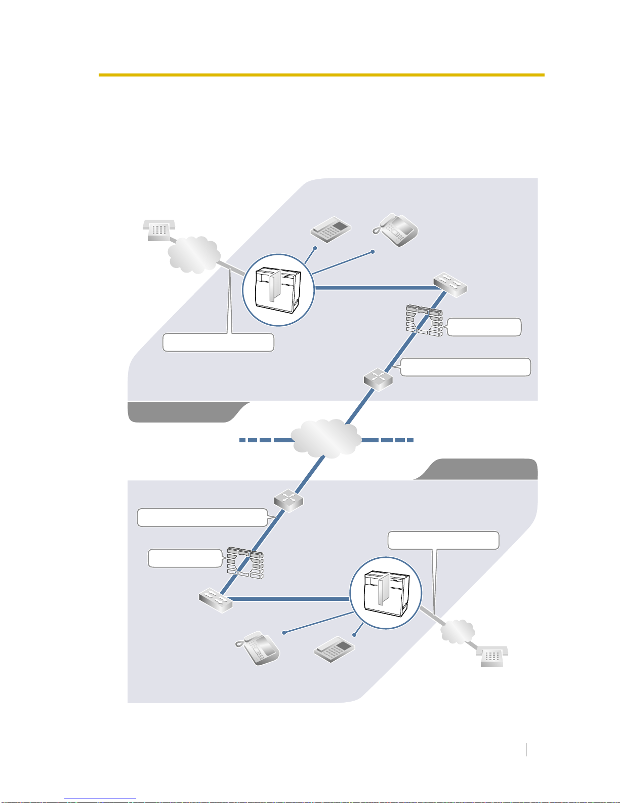
1.1 Example Network Diagramme ............................................................................. 4
1.2 Network Devices and Numbering Plan............................................................... 5
1.2.1 Numbering Plan Example ................................................................................. 6
2 Physical Installation......................................................................9
2.1 Installation........................................................................................................... 10
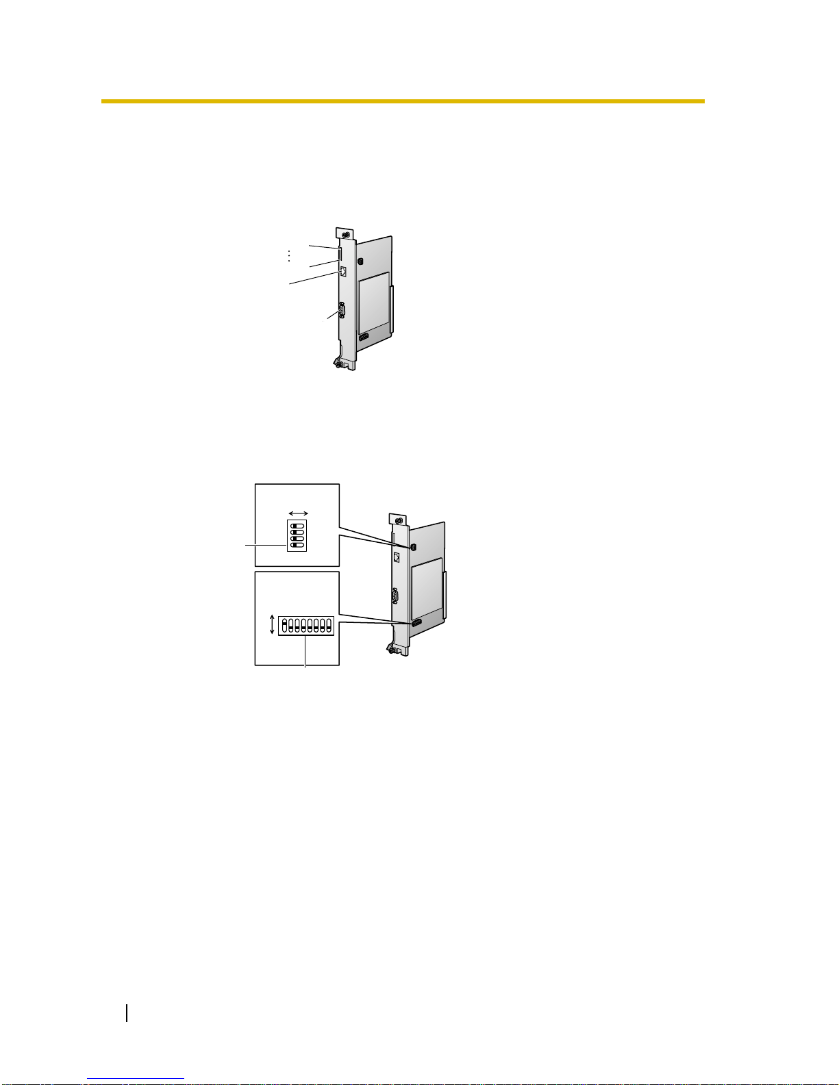
2.1.1 Names and Locations ..................................................................................... 10
2.1.2 DIP Switch Settings ........................................................................................ 10
2.1.3 Installing the IP Gateway Card to the Hybrid IP-PBX ......................................11
2.1.4 Indication Light (LED) ..................................................................................... 12
2.2 Cable Connection ............................................................................................... 13
2.2.1 RS-232C Cable Connection............................................................................ 13
2.2.2 10 Base-T Cable Connection.......................................................................... 13
3 Trunk Programming of the Hybrid IP-PBX ................................15
3.1 Trunk Programming of the Hybrid IP-PBX ....................................................... 16
4 Logical Installation (Maintenance Console Software) .............19
4.1 The Maintenance Console Software (MCS) ..................................................... 20
4.1.1 Installing the MCS ........................................................................................... 20
4.1.2 Starting MCS and Logging-in .......................................................................... 21
4.1.3 MCS Main Directory Window .......................................................................... 21
4.1.4 Serial Port Setting ........................................................................................... 22
4.1.5 Changing the Password.................................................................................. 23
4.2 Creating New Group and Gateway.................................................................... 24
4.2.1 Creating a New Unit Group (Office) ................................................................ 24
4.2.2 Creating a New Gateway (IP Gateway Card) ................................................. 24
4.3 Configuring Domain Name System (DNS) Data............................................... 27
4.3.1 Editing DNS Data............................................................................................ 27
4.4 Configuring Office Data ..................................................................................... 29
4.5 Transferring the Data to the IP Gateway Card ................................................. 32
4.6 Synchronising Time and Date of the IP Gateway Card................................... 33
5 Optimising Performance ............................................................ 35
5.1 Preventing Problems.......................................................................................... 36
5.1.1 Voice Volume .................................................................................................. 36
5.1.2 Transmission Delays....................................................................................... 36
5.1.3 Priority Control ................................................................................................ 37
5.1.4 Recovery Delay and Jitter Buffer .................................................................... 37
5.1.5 Internet, Intranet, and Virtual Private Networks (VPN) ................................... 37

Getting Started 3
Section 1
Overview
Panasonic Hybrid IP-PBX with KX-TDA0480, IP
Gateway Card, will allow organisations to route both
voice and fax communications over digital data
networks.
The KX-TDA0480, designed to be easily integrated into
existing LAN/WAN environments, seamlessly bridges
Public Switched Telephone Network (PSTN) and
analogue telephone with digital data networks without
interrupting or compromising ongoing data
communications. Because communications do not take
place over conventional telephone networks, the high
cost of long distance communications is virtually
eliminated.

1.1 Example Network Diagramme
4 Getting Started
1.1 Example Network Diagramme
The following diagramme illustrates a simple VoIP network connecting Hybrid IP-PBXs at 2
different locations. The IP Gateway Card converts outgoing voice or fax signals into IP data
packets for transmission. On the incoming side, it reverses this process and translates the
packets back into appropriate voice or fax signals.
PSTN
(Public Switched
Telephone Network)
LAN
PSTN
Voice signals are converted
into IP data packets.
Router
Switching HUB
Hybrid IP-PBX
with IP Gateway Card
Firewall
Other data packets.
Voice data packets.

1.2 Network Devices and Numbering Plan
Getting Started 5
1.2 Network Devices and Numbering Plan
Once the installation of IP Gateway Cards begins, network configuration information needs to
be on-hand. The following diagramme illustrates devices found in an IP network. Referring to
this example, consult your network administrator to obtain necessary information to configure
your own network.
PSTN
(Public Switched
Telephone Network)
LAN
Chicago Office
PBX Office Code: 41
Gateway Unit IP: 199.176.64.41
IP Trunk number: 801
PSTN
Local Telephone
123-4567
Extn. 301
(300-399)
PBX Office Code: 35
Gateway Unit IP: 200.45.11.35
IP Trunk Number: 801
Extn. 201
(200-299)
Local Telephone
456-7890
G3 Fax Extn. 501
(500-599)
G3 Fax Extn. 601
(600-699)
IP: 200.45.11.1
Subnet Mask: 255.255.255.0
PSTN Trunk Number: 9
Subnet Mask: 255.255.255.0
Los Angels Office
IP: 200.45.11.1
PSTN Trunk Number: 9

1.2 Network Devices and Numbering Plan
6 Getting Started
Notes
•Recommended IP Networks: the IP Gateway Card's quality of performance depends
on the type of network in use. For instance, transmission delays due to congestion on
the network and inadequate service characteristics of Internet Service Provider (ISP)
can both contribute to loss in voice communications. Manageable networks (e.g., LAN)
in which static*1 IP addresses can be used provide better quality of service compared to
unmanageable networks such as the Internet.
•Firewalls: a firewall protects the internal networks of an organisation against
unauthorised penetration from outside. However, routing a VoIP network through a
firewall may cause performance degradation. Check with your network administrator of
the existence of firewall.
1.2.1 Numbering Plan Example
This section describes the network numbering mechanism based on the previous example
diagramme. Please configure your network referring to this example.
IP Addressing Information
IP addressing information is typically supplied by a network administrator. Consult your
network administrator for specific values.
*1 Dynamic IP addressing (using DHCP/BOOTP) is not supported.
Description Los Angels
Office
Chicago
Office
Gateway IP
Address
The Gateway IP address identifies the
location of each unit in the network during
VoIP communications. A unique IP address
must be assigned to each unit.
200.45.11.35 199.176.64.41
Route IP
Address
(Firewall or
Router)
When the IP Gateway Card is routed
through a firewall, the internal IP address of
firewall becomes the Gateway address to be
associated with the IP Gateway Card
instead of the router IP address.
200.45.11.1 199.176.64.1
Subnet Mask
Address
Each network location has a subnet mask
address that helps to define which digits of
an IP address are used for the network
address and the host address. Each
Gateway IP addresse must fall within the
same subnet as that of the router shared by
the units.
255.255.255.0
(default)
255.255.255.0
(default)

1.2 Network Devices and Numbering Plan
Getting Started 7
PBX Numbering Information
PBX numbering information is necessary to setup phone numbers for a VoIP network.
Configure the numbers conforming to existing PBX numbering systems.
Dialling Examples
The VoIP network allows you to access the PBX at one location from another to establish: (1)
an extension call, or (2) an outside call through local PSTN as if you are calling from the same
area.
Calling from Los Angels to Chicago
To extension 301 via IP network
To local telephone 123-4567 via IP network through local PSTN
Description Los Angels
Office
Chicago
Office
PBX Office
Code
A unique number (ranging from 1 to 8 digits)
assigned to identify each Hybrid IP-PBX within a
network. In this example, for convenience, each
PBX Office Code corresponds to the last portion of
the IP address of its Gateway unit; that is, because
Los Angels Office unit has the IP address of
200.45.11.35, Los Angels PBX Office Code is 35.
35 41
IP Trunk
Number
An access number to seize an IP trunk. Any
available trunk number can be assigned as an IP
Trunk Number.
801 801
PSTN Trunk
Number
An access number to seize a local PSTN trunk. 99
Extension
Number
A number assigned to each extension. 200-299 300-399
Dial 41.Dial 801. Dial 301.
Chicago PBX
office code
extension no.
IP trunk
no.
Dial 41. Dial 9.Dial 801. Dial 123-4567.
Chicago PBX
office code
phone no.
Chicago PBX
PSTN trunk no.
IP trunk
no.

1.2 Network Devices and Numbering Plan
8 Getting Started
Calling from Chicago to Los Angels
To extension 201 via IP network
To local telephone 456-7890 via IP network through local PSTN
PBX Connection Information
PBX connection information is created by combining IP Addressing Information and PBX
Numbering Information. According to the sample below, please create your own PBX
connection information.
•Terminal Number: The number composed of the
PBX Office Code followed by the first digit from the
destination number. See the example on the right.
•Remaining Digits: The number of digits needed to be
dialled in addition to the Terminal Number to access
the destination. (Setting, for example, remaining digits
to 7 does not mean that the user must dial all 7 digits
when making a call.) See the example on the right.
•Signal Port Number: The TCP port number on which call control signal transmission will
occur. When installing the IP Gateway Card within a firewall as in this example, voice and
fax packets must routed through specified firewall ports. Consult your network
administrator for specific values.
•Access IP Address: The IP address of each unit in the network (as the access
destination).
Los Angels PBX (Office Code: 35) Chicago PBX (Office Code: 41)
Extensions FAX
Extensions
PSTN
Access
Extensions FAX
Extensions
PSTN
Access
Terminal
Number 352 355 359 413 416 419
Remaining
Digits 2 272 27
Signal Port
Number
1720
(default)
1720
(default)
Access IP
Address 200.45.11.35 199.176.64.41
Dial 35.Dial 801. Dial 201.
Los Angels PBX
office code
extension no.
IP trunk
no.
Dial 35. Dial 9.Dial 801. Dial 456-7890.
Los Angels PBX
office code
phone no.
Los Angels PBX
PSTN trunk no.
IP trunk
no.
352+00-99
PBX Office
Code
Remaining Digits
Terminal No.
Los Angels extensions
First digit of
the extension
number
Remaining digits
of the extension
number

Getting Started 9
Section 2
Physical Installation

2.1 Installation
10 Getting Started
2.1 Installation
2.1.1 Names and Locations
2.1.2 DIP Switch Settings
The default DIP Switch settings are as illustrated below. Confirm that the switches are in the
default positions before installing the IP Gateway Card.
Indication Lights LED1
IP Link Connector
Serial (RS-232C) Connector
LED8
Dip Switch
Dip Switch
123SW
ON
OFF
45678
123
SW4
ON
OFF
4

2.1 Installation
Getting Started 11
2.1.3 Installing the IP Gateway Card to the Hybrid IP-PBX
1. Insert the card along the guide rails.
2. Holding the card as shown on the left, push the
release lever in the direction of the arrow so that the
card is made to engage with the connector on the
back board securely.
3. Turn the screws clockwise to fix the card.
Guide Rails
1
2
Back Board
screws

2.1 Installation
12 Getting Started
2.1.4 Indication Light (LED)
LED1 Green/Red Channel Status
Off: Power Off
Green Flash: Normal (channel used)
Red On: During reset
Red Flash: Out of Service
LED2 Green Online Status
On: On-line mode
Flash: Emergency maintenance mode
LED3 Red Alarm
Off: Normal
On: Alarm
LED4 Green Busy status
Off: Not used
On: At least one line is used
LED5 Green Link status
Off: Connection error
On: Normal Connection
LED6 Green Data transmission
Off: No data transmitted
On: Data transmitting
LED7 Green Collision status
Off: No data collision
On: Data collision
LED8 Green SIOSEL
Off: CPU port used (Maintenance port not
available)
On: Maintenance port available
LED 1
LED 2
LED 3
LED 4
LED 5
LED 6
LED 7
LED 8

2.2 Cable Connection
Getting Started 13
2.2 Cable Connection
2.2.1 RS-232C Cable Connection
To initialise a newly installed IP Gateway Card using the Maintenance Console Software (see
4.2 Creating New Group and Gateway), a computer or terminal must be connected directly to
the unit using an RS-232C serial (cross) cable with DB9 Female to DB9 Female connectors.
1. Turn the computer power OFF.
2. Connect the RS-232C cable to one of the PC's COM ports (e.g., COM 1) and to the Serial
Port connector on the IP Gateway Card front panel.
2.2.2 10 Base-T Cable Connection
A standard 10 Base-T cable with an RJ-45 connector is used to interconnect the IP Gateway
Card with a network device.
1. Insert the RJ-45 connector into the IP Gateway Card Uplink port located on the IP Gateway
Card front panel.
2. Connect the other end of the 10 Base-T cable to the remote LAN equipment.
When connecting the Hybrid IP-PBX directly to a router or PC, use a 10 Base-T Cross/Rollover
cable. Use a 10 Base-T straight cable to connect the Hybrid IP-PBX to a switching HUB.
Circuit Type (EIA)
AA
BA
BB
CA
CB
CC
AB
CF
CD
Signal Name
FG
SD (TXD)
RD (RXD)
RTS
CTS
DR (DSR)
SG
DCD
ER (DTR)
Pin No.
1
2
3
4
5
6
7
8
20
Circuit Type (EIA)
CE
BB
BA
CA
CB
CD
AB
CC
CF
Signal Name
RI
RXD
TXD
RTS
CTS
DTR
SG
DSR
DCD
Pin No.
9
2
3
7
8
4
5
6
1
RS-232C port on the IP Gateway Card
COM port on the PC
PC Hybrid IP-PBX
RS-232C Serial Cable (Cross cable)
To COM port To IP Gateway Card
RS-232C port
10 Base-T straight cable
10 Base-T cross cable (Rollover)
Router
Router
or
Switching HUB
PC or Hybrid IP-PBX

2.2 Cable Connection
14 Getting Started

Getting Started 15
Section 3
Trunk Programming of the Hybrid IP-PBX

3.1 Trunk Programming of the Hybrid IP-PBX
16 Getting Started
3.1 Trunk Programming of the Hybrid IP-PBX
In order to assign Trunk Group Number to the IP trunk of the Hybrid IP-PBX, follow the
procedure below.
Note
It is assumed that you have already installed the PC Programming Software in your PC.
1. Double-click "TDA PC Programming" icon.
2. Type the password, then click [OK] to log-in.
3. Select "File" "New".
4. Double-click "Slot" under "Configuration".
5. Select "IP-GW4" for "Card Type" for the
appropriate Slot, then click [OK].
6. Double-click "CO" under "Line".
Pending

3.1 Trunk Programming of the Hybrid IP-PBX
Getting Started 17
7. Enter CO Name (max. 20 characters) and
Trunk Group Number (01-64) for the desired
"Trunk (CO) Number", then click [OK] to
enable the setting.
8. Select "Connect" "Disconnect" to end
configuration.

3.1 Trunk Programming of the Hybrid IP-PBX
18 Getting Started

Getting Started 19
Section 4
Logical Installation (Maintenance Console
Software)
This section describes the logical installation process
involving the following operations: (1) create New
Groups and Gateway units, (2) configure common DNS
Data, (3) configure unit-specific Office Data, and (4)
upload configuration files and reboot the units.

4.1 The Maintenance Console Software (MCS)
20 Getting Started
4.1 The Maintenance Console Software (MCS)
MCS provides easy-to-use installation and management of the IP Gateway Card. This section
describes the procedures to install and configure the IP Gateway Card for basic use. Use the
MCS when installing the IP Gateway Card for the first time to establish the unit's new IP
addressing through direct RS-232C link to the unit. Once this is done and units are on-line in
the network, the MCS can be used to configure and troubleshoot units remotely.
For a complete listing of all MCS features and functions, refer to the IP Gateway Card
Programming Guide.
System Requirements
• Microsoft® Windows® 95, Windows 98 or Windows NT 4.0® or later
• Minimum requirements (for installing Maintenance Console Software only)
CPU: Pentium® ??? MHz
RAM: ??? MB
HDD: ??? MB
Trademarks
• Microsoft, Windows and Windows NT are either registered trademarks or trademarks of
Microsoft Corporation in the United States and/or other countries.
• Pentium is a trademark or a registered trademark of Intel Corporation or its subsidiaries
in the United States and other countries.
• All other trademarks identified herein are the property of their respective owners.
4.1.1 Installing the MCS
The MCS is shipped on CD-ROM.
1. a. Insert the CD-ROM into the PC's CD-ROM
drive.
b. Click "Maintenance Console Software
Installer" on the initial screen.
c. Click [OK].
d. Double-click "Setup.EXE" icon.
2. Follow the instructions to install the MCS.
Other manuals for KX-TDA0480
2
Table of contents
Other Panasonic Gateway manuals

Panasonic
Panasonic KX-TDA0480 User manual

Panasonic
Panasonic KX-TDA0480 User manual

Panasonic
Panasonic KX-TDA0484 Operating instructions

Panasonic
Panasonic KX-TDA3480 Operating instructions

Panasonic
Panasonic KX-TDA0490 User manual

Panasonic
Panasonic KX-HGW200 User manual

Panasonic
Panasonic KX-TDA0490 User manual

Panasonic
Panasonic MKG100C913 User manual

Panasonic
Panasonic Live Production Suite Series User manual

Panasonic
Panasonic KX-TDA0484 User manual