manuals.online logo
Brands
  1. Home
  2. •
  3. Brands
  4. •
  5. Panasonic
  6. •
  7. Intercom System
  8. •
  9. Panasonic VL-V700 User manual

Panasonic VL-V700 User manual

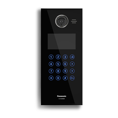
Lobby Station [VL-V900] up to 3 units (up to 18*)
Extension Box [VL-V703] up to 3 units
Control Box [VL-V700] up to 1 unit
Distribution Box [VL-V701] up to 28 units
Main Monitor up to 560 units
Lift Controller [VL-V702] up to 15 units (up to 3 Lifts)
DIP
switches
Repeater
switch
Termination
switch
Main Monitor
(up to 20)
#1
#20
Power
Supply
Unit
Power
Supply
Unit
Distribution Box #1-2
IN OUT
Repeater
12345678
ON
OFF (on) (on)
Distribution box DIP switches Repeater switch Termination switch
12345678
ON
OFF (off)
12345678
ON
OFF (off)
ON
OFF (off)
ON
OFF (off)
12345678
ON
OFF (off)
12345678
ON
OFF (off)
12345678
ON
OFF (off) (on)
(off)
(off)
(off)
(off)
(off)
(off)
#1-4
#1-7
#1-6
#1-5
#1-3
#1-2
#1-1
12345678
12345678
NP: Non-polarised
COAX
DC IN
V700 K-OUTK-IN
L2L1 C2C1 S2S1
ONOFF
USB
DC IN
RJ11
Branch #1
Lobby Station (up to 18)
Extension Box (3) Control Box (1)
NP
NP
NP PC
NP
12 V DC
NP
Access
controller
(input)
Electric
lock
(output)
TV Monitor
PBX
(6 lobby station for each
extension box)
DC IN
NP
DIP SW 1 : ON
1
Lift Controller
(up to 15 for Relay)
Lift Controller
(up to 3 for Binary)
Distribution Box #1-1
*Up to 18 Lobby Ststion can be installed by adding Extension Boxes.
Power Supply Unit
Power
Supply
Power
Supply Unit
NP
NP
NPNP
NPNP
NP
NP
NP
NP
NP
NP
NP
Distribution
Box #1-4 Distribution
Box #1-7
Distribution
Box #1-5
Distribution
Box #1-3 Distribution
Box #1-6
Branch #2
Branch #3
Branch #4
Lobby Station #6
Lobby Station #5
Lobby Station #4
Lobby Station #3
Lobby Station #2
Repeater
Power
Supply Unit
Wiring Distance *Use PE(polyethylene)-insulated cables.
Wiring run Wire diameter
0.65 mm (22 AWG) 1.2 mm (17 AWG)
100 m 200 m
100 m
100 m
100 m
100 m
200 m
200 m
200 m
200 m
Lobby Station - Control Box
Control Box - Distribution Box (Standard Mode)
Distribution Box (Standard Mode) - Main Monitor
Control Box - Distribution Box (Repeater Mode)
Distribution Box (Repeater Mode) - Distribution Box (Standard Mode)
Key Features
VL-V900
Lobby Station
VL-V700
Control Box
VL-V701
Distribution Box /
Repeater Box
VL-V702
Lift Controller
VL-V703
Extension Box
• Large-capacity, expandable:
The system supports up to 560 room units (main monitors) and 3 lobby stations.
Optional devices such as cameras, access controllers (door openers, key switches, card scanners, etc.), electric locks, and a TV monitor can be connected.
The system can be integrated with a Panasonic PBX system used by facility staff.
Extension boxes can be used to increase the number of lobby stations that can be used in the system. Up to 3 extension boxes can be connected to the control
box, and up to 6 lobby stations can be connected to each extension box. In all, the system supports up to 18 lobby stations.
• Easy to install, congure and maintain:
The system mainly needs only 2 wire cables (1 pair of cables), and minimal equipment.
System settings can be congured in advance using a computer, and uploaded on-site via USB connection.
System settings can be congured on-site using a lobby station, main monitor, and PBX extension telephone.
System events can be logged on an optional SD card (up to 90,000 images captured by a lobby station camera with text logs).
• Convenient features for residents, visitors, and facility staff:
The system can be used in the “room mode” (visitors can call rooms directly) or “reception mode” (visitors calls are routed through a receptionist).
Visitors can use a lobby station to call residents or facility staff.
Residents can use their room monitors to monitor lobby stations and optional cameras, and can allow visitors to enter the lobby and lift.
Residents can use their room monitors to make emergency calls to facility staff. (Not available with the VL-MW251)
Facility staff can make and receive calls to and from residents and visitors.
Wiring Diagram
Accessory Information
Optional Accessories
Video Intercom System
for Apartment complexes
For the Lobby Station
Flush mount box x1, Screw for Flush mount box (4 mm x 25 mm) x4, Hex wrench x1, Power supply
unit x1 (AC cable is not included.)
Screw for power supply unit (4 mm x 40 mm) x2, Cable binder x2
For the Control Box, Distribution Box, Lift Controller, Extension Box
Screw for mounting the box (3.8 mm x 20 mm) x2, Power supply unit x1 (AC cable is not included.)
Screw for power supply unit (4 mm x 40 mm) x2, Cable binder x3
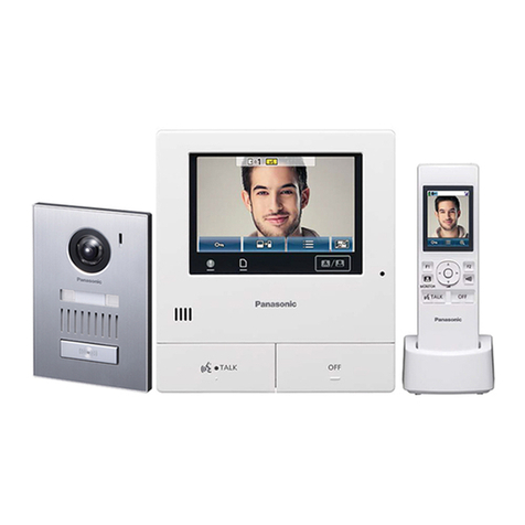
Main Monitor
(Smartphone Connect
Model)
VL-MVN511
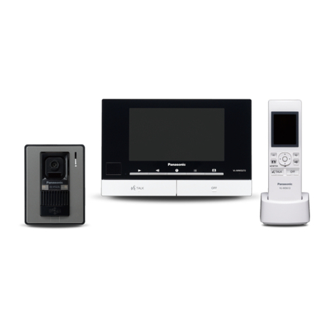
Main Monitor
(2.4GHz Wireless
Monitor Connect Model)
VL-MW251
Main Monitor
(DECT Wireless Monitor &
Wired Monitor Connect Model)
VL-MWD272
Setup tool, USB driver, manual and
the latest rmware
Download information is available at the
following web site.
http://panasonic.net /pcc/support /intercom/v900
VL-V900 and VL-V700 series
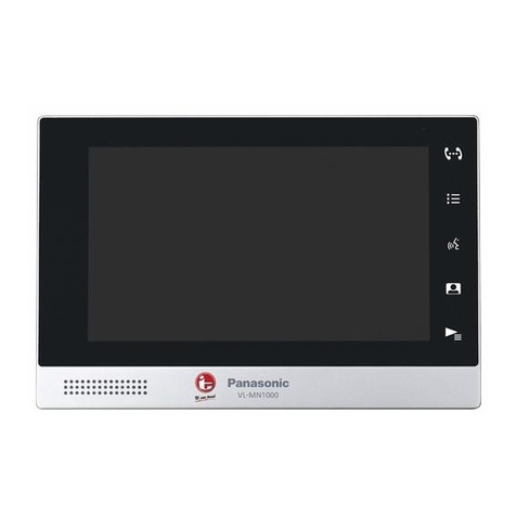
Main Monitor
(Standard Model)
VL-MV26
3.5-inch
5-inch
wide
7-inch
wide
5-inch
wide
VL-V900 VL-V700 VL-V701 VL-V703
Model number and name
Dimensions
Power source
Power consumption
Dimensions (H x W x D)
(Excluding protruding sections)
Weight
Operating environment
Display
Image sensor
Viewing angle
(1/4 inch) CMOS sensor (approx. 1M pixels)
4.3-inch monochrome display (white backlit LCD)
Display language English
—
—
—
—
—
—
—
—
2.0 kg 400 g
Power supply unit (VL-PS240) 24 V DC, 0.2 A
Standby: Approx. 1.9 W
During operation: Approx. 4.5 W
Standby: Approx. 3.5 W
During operation: Approx. 3.7 W
Standby: Approx. 1.2 W
During operation: Approx. 2.0 W
Standby: Approx. 0.4 W
During operation: Approx. 4.4 W
Standby: Approx. 1.5 W
During operation: Approx. 1.5 W
Power supply unit (VL-PS240: AC 220-240 V)
108.5 x 210 x 52.5 mm
Lobby Station Control Box Distribution Box / Repeater Box Extension Box
VL-V702
Lift Cotrol Box
Ambient temperature: Approx. -10 °C to +55 °C,
Relative humidity (non-condensing): up to 90 % Ambient temperature: -10°C to +50°C, Relative humidity (non-condensing): up to 90 %
(indoor use only)
373 x 179 x 2.5 mm (excluding sections embedded
into the wall) Flush mounting only
Horizontally: Approx. 170˚, Vertically: Approx. 115˚
*1 Up to 18 Lobby Stations can be installed by adding Extension Boxes. *2 Water resistance is only assured if the Door Station is installed correctly according to the instructions in the Installation Guide, and appropriate water protection measures are taken.
*3 Text logs: More than 90,000 items / Images: Up to 90,000 images
Up to 28 Up to 15 Up to 3
Up to 3
(Up to 18*1)
Talking method Hands-free
Minimum illuminance required 1 lx (within approx. 50 cm from the camera lens)
Lighting method White coloured LED lights
IP rating / IK rating IP55*2/ Compliant with IK07
Installation method Flush mount (ush mounting box supplied) Wall implanted (or can be installed on DIN rail)
External material Aluminium / stainless steel Flame retardant ABS resin
Supported functions
Support for electric lock releasing (entrance unlocking) x 1
VIDEO-IN (recommended Panasonic CCTV) x 1
Guidance (simple usage for visitors)
Night colour vision (white coloured LED lights)
Heat sensor: The backlight of the display and buttons are
turned on when a visitor is detected.
Display the resident’s names
Unlock with PIN-code
Extend Lobby StationsSupported control methods
•1:1 control (Relay signalling)
•Binary control
Dip switch
•Mode change
(Distributor mode / Repeater mode)
•Termination setting
(Normal / Terminal)
•ID setting
(1-7 by binary number)
USB connection
(provide PC application / English)
•
date and time setting
•
set the room number with the monitor
•
estimate the status of the equipment
in the system
•
operation setting
(terminal, pass code, and so on.)
SD Card (SD / SDHC / SDXC): Log function*3
VIDEO OUTPUT (NTSC up to 1)
RJ-11: connect with PBX system
Power
Supply
Unit
Power
Supply
Unit
Power
Supply
Unit
Power
Supply
Unit
Power
Supply
Unit
Specications
Trademarks and registered trademarks
- SD, SDHC and SDXC are trademarks of SD-3C, LLC.
Important
- Safety Precaution: carefully read the operating instructions and installation manual before using this product.
• The actual product may vary slightly from photograph.
• All pictures of the LCD display are simulated.
• Weights and dimensions are approximate.
• Design and Specifications are subject to change without notice.
• These products may be subject to export control regulations.
DISTRIBUTED BY :
MG-DHPL016EN 1607TD/ZZZ-1
Installing the Lobby Station
Installing the Control Box, Dirstribution Box, Lift controler, Extension Box Installing the Power Supply Unit
Installing the VL-MV26 Main Monitor
VL-MV26
Model number and name
Dimensions
Power source
Power consumption
Weight
Operating environment
Display 3.5-inch, colour / QVGA (320x240 pixel)
Display language English
330 g
Power supply unit (VL-PS240) 220-240 V AC
Standby: Approx. 1.2 W, During operation: Approx. 8 W
Power
Supply
Unit
169
29
129
Main Monitor
Ambient temperature: Approx.0 °C to +40 °C
Relative humidity (non-condensing): up to 90 %
Picture recording Up to 30 images (up to 30 visitors, 1 shot per visitor)
External material Flame retardant ABS resin
Supported functions •1 door bell input
•Electric lock release (public)
•Monitor security camera
•Connecting to a PBX system
•Emergency call
Installation position
Side view Approx.
2300 mm
Approx. 115°
Approx.
500 mm
Approx.
Approx.
mm0051.xorppA
Centre of
the Camera
lens
1600 mm
700 mm
Top view
(view when looking from above)
Approx. 500 mm
Approx. 170°
Image range
Front view
353 mm
159 mm
Side view
80 mm
Mounting on a DIN rail Attaching directly to a wall
1
2
Mount the control box on the DIN rail
using the hooks .
1
2
Attach the unit to the wall securely using
the 2 supplied screws .
3
3
AC cable
DC cable
45 mm
7 mm
25 mm
7 mm
Front view
the
screws
Top view
Bottom view
AC
cable
binder
hole
AC IN terminal
DC
cable
binde
hole DC OUT terminal
83.5 mm
Screws
Wall
Wire (Not included)
Mounting bracket
NP
NP
NP
NP
DC IN
Distribution Box Main Monitor
(up to 20 per Distribution box)
Door Bell
POWERSUPPLY UNIT
NP: Non-polarised
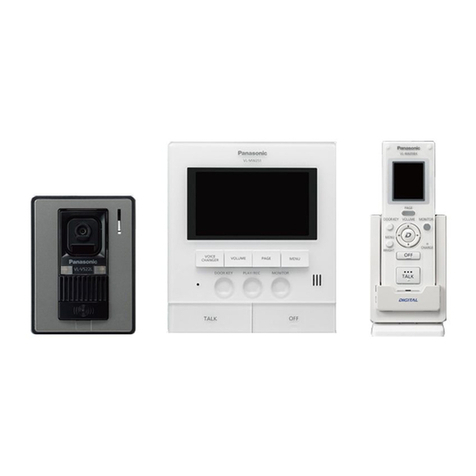
This manual suits for next models

5

Other Panasonic Intercom System manuals

Panasonic VL-GC3700BX Technical manual

Panasonic

Panasonic VL-GC3700BX Technical manual

Panasonic VL-SV71 User manual

Panasonic

Panasonic VL-SV71 User manual

Panasonic VL-SWD272 User manual

Panasonic

Panasonic VL-SWD272 User manual

Panasonic KX-T7775 User manual

Panasonic

Panasonic KX-T7775 User manual

Panasonic VL-V900 User manual

Panasonic

Panasonic VL-V900 User manual

Panasonic VL-SV71 User manual

Panasonic

Panasonic VL-SV71 User manual

Panasonic VL-MV72AZ User manual

Panasonic

Panasonic VL-MV72AZ User manual

Panasonic VL-SWD501AZ User manual

Panasonic

Panasonic VL-SWD501AZ User manual

Panasonic VL-SWD272 User manual

Panasonic

Panasonic VL-SWD272 User manual

Panasonic VL-V900 User manual

Panasonic

Panasonic VL-V900 User manual

Panasonic VL-GM301A Operating instructions

Panasonic

Panasonic VL-GM301A Operating instructions

Panasonic VL-V900 User manual

Panasonic

Panasonic VL-V900 User manual

Panasonic VL-SVN511 Series User manual

Panasonic

Panasonic VL-SVN511 Series User manual

Panasonic KX-T30865 User manual

Panasonic

Panasonic KX-T30865 User manual

Panasonic VL-SWD273 User manual

Panasonic

Panasonic VL-SWD273 User manual

Panasonic VG-M186D User manual

Panasonic

Panasonic VG-M186D User manual

Panasonic VL-MVN511 User manual

Panasonic

Panasonic VL-MVN511 User manual

Panasonic VL-SVN511 Series User manual

Panasonic

Panasonic VL-SVN511 Series User manual

Panasonic VL-VN1800 User manual

Panasonic

Panasonic VL-VN1800 User manual

Panasonic VL-VN1800 User manual

Panasonic

Panasonic VL-VN1800 User manual

Panasonic VL-SW250BX User manual

Panasonic

Panasonic VL-SW250BX User manual

Panasonic VL-V900 User manual

Panasonic

Panasonic VL-V900 User manual

Panasonic VL-MV10 User manual

Panasonic

Panasonic VL-MV10 User manual

Panasonic VL-SWD501 User manual

Panasonic

Panasonic VL-SWD501 User manual

Popular Intercom System manuals by other brands

3M 478DA (D-15) installation guide

3M

3M 478DA (D-15) installation guide

Elvox 5721 Installer manual

Elvox

Elvox 5721 Installer manual

Genway C-5 SYSTEM G9 Villa Door Station Series user manual

Genway

Genway C-5 SYSTEM G9 Villa Door Station Series user manual

AES global Styluscom Video manual

AES global

AES global Styluscom Video manual

AES MultiCOM Lite 4G manual

AES

AES MultiCOM Lite 4G manual

Novasub xDR-DSP Operation manual

Novasub

Novasub xDR-DSP Operation manual

Chamberlain LiftMaster ELITE EL25 instruction manual

Chamberlain

Chamberlain LiftMaster ELITE EL25 instruction manual

SEA Wi-Fi Com installation instructions

SEA

SEA Wi-Fi Com installation instructions

ELRO Pro PV40-P2M2 manual

ELRO

ELRO Pro PV40-P2M2 manual

Smartwares VD36W manual

Smartwares

Smartwares VD36W manual

Comelit Simplebus2 Ultra UT2010 Technical manual

Comelit

Comelit Simplebus2 Ultra UT2010 Technical manual

urmet domus Miwi Matibus SE manual

urmet domus

urmet domus Miwi Matibus SE manual

Caliber HWC 502 instruction manual

Caliber

Caliber HWC 502 instruction manual

Akuvox E18C Administrator's guide

Akuvox

Akuvox E18C Administrator's guide

Aiphone LC-10S instructions

Aiphone

Aiphone LC-10S instructions

SCS Sentinel VisioKit 7 Installation and user manual

SCS Sentinel

SCS Sentinel VisioKit 7 Installation and user manual

Grandstream Networks GSC3510 Quick installation guide

Grandstream Networks

Grandstream Networks GSC3510 Quick installation guide

BARIX Annuncicom user manual

BARIX

BARIX Annuncicom user manual

manuals.online logo
manuals.online logoBrands
  • About & Mission
  • Contact us
  • Privacy Policy
  • Terms and Conditions

Copyright 2025 Manuals.Online. All Rights Reserved.