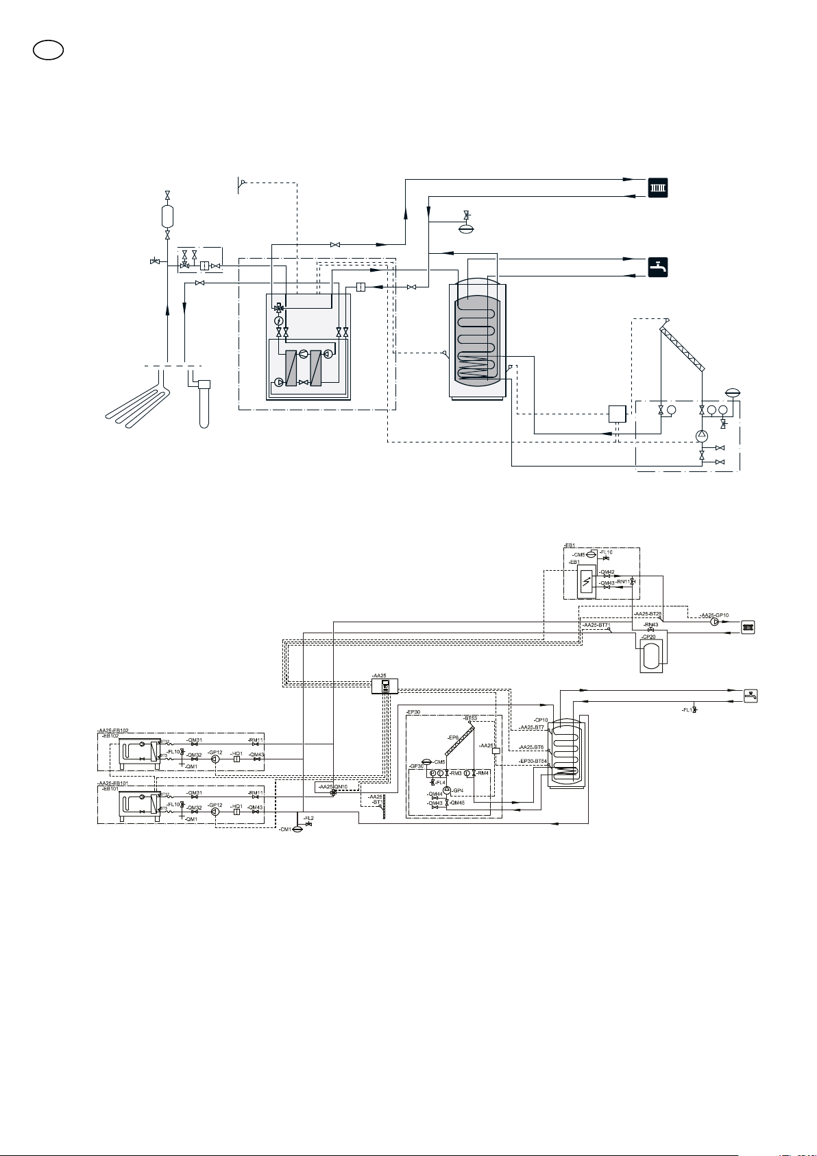
Outline diagram
Explanation
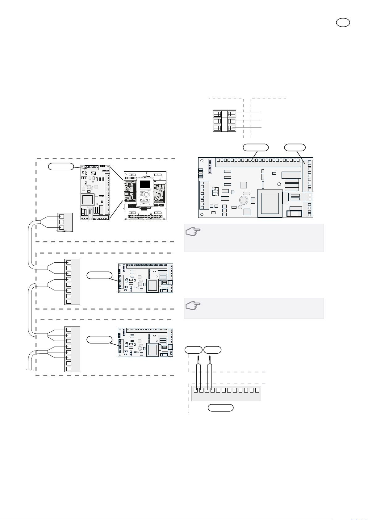
Control moduleAA25
Temperature sensor, outdoorBT1
Heat pump systemAA25-
EB100–102
Temperature sensor, hot waterBT6
Temperature sensor, external flow lineBT25
Temperature sensor, external return lineBT71
Heat pumpEB100–102
Cooling module AEP14
Cooling module BEP15
Safety valve, collector sideFL10–11
Safety valve, heating medium sideFL12–13
Charge pumpGP12
Particle filterHQ1,
HQ12–15
Tapping valveQM1
Shutoff valve, supply lineQM31
Shut-off valve, return lineQM32
Shut-off valveQM43
Shut-off valve, brine sideQM50–53
Shut-off valve, heating medium sideQM54–57
Reversing valve, heating/hot waterQN10
Non-return valveRM10–13
External additional heatEB1
Expansion vessel, closedCM5
External electrical additional heatEB1
Safety valve, heating medium sideFL10
Shut-off valve, heating medium sideQM42–43
Trim valveRN11
Solar heating installation/SOLAR 42EP30
Solar panelEP8
Pump stationGP30
Expansion vessel, closedCM5
Safety valve, solarFL4
Circulation pump, solarGP4
Shut-off valveQM43–45
Non-return valveRM3–4
Accessory card SOLAR 42AA25
Sensor, solar panelBT53
Sensor, solar coilBT54
Hot water comfortQZ1
Accessory cardAA5
Temperature sensor, hot water flowBT70
Mixer valve, hot waterFQ1
Circulation pump, domestic hot water cir-
culation
GP11
Non-return valveRM23
Trim valveRN20
Miscel-
laneous
Manometer, brine sideBP6
Expansion vessel, heating medium sideCM1
Level vessel
CM2
Expansion vessel, brine sideCM3
Accumulator tank with solar coilCP10
Buffer vesselCP20
Water heaterEB10
Ground-source heating/Ground collectorEP12
Safety valve, heating mediumFL2
Safety valve, brineFL3
Circulation pump, heating medium extern-
al
GP10, GP18
Non-return valveRM21
Filler valve, brineQM12
Venting valve, brine sideQM21
Shut off valve, brine returnQM33
Shut off valve, brine flowQM34
Shut-off valveQM42
Filling set, brineXL15
Connection, filling brineXL27–28
Designations in component locations according to
standard IEC 81346-1 and 81346-2.
13
GB