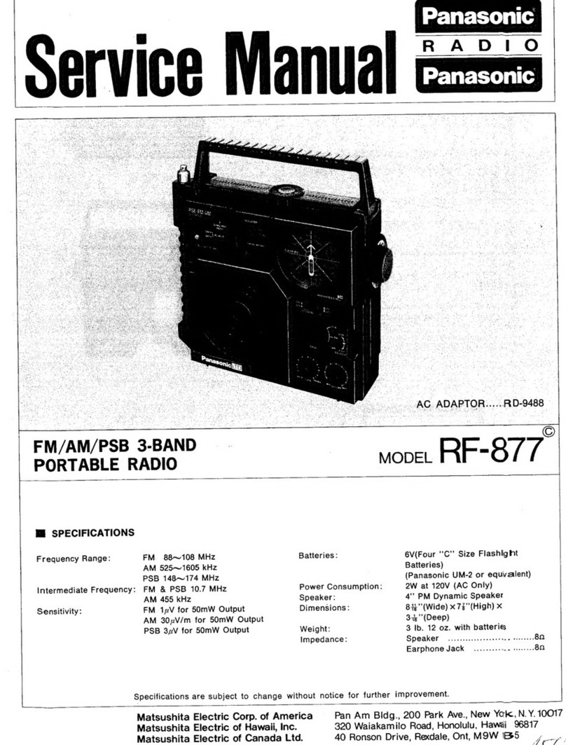
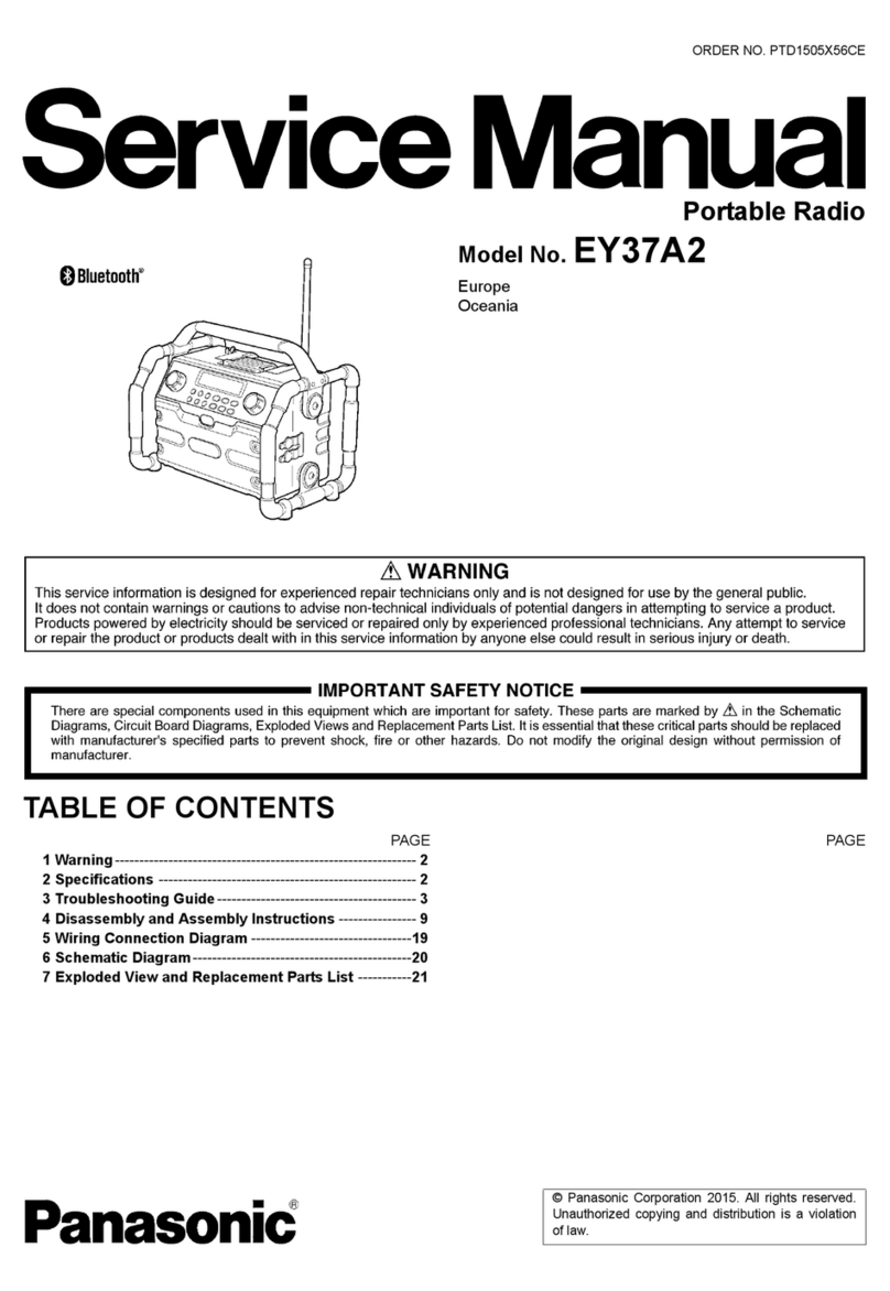
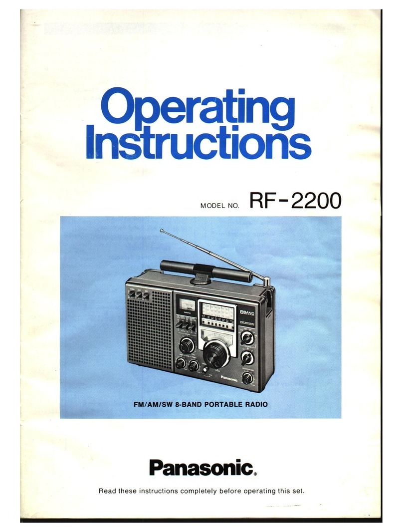
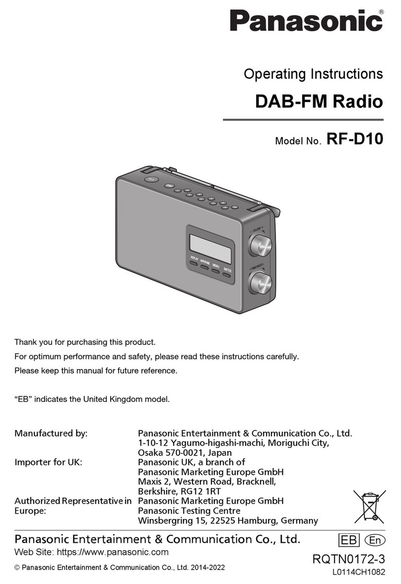
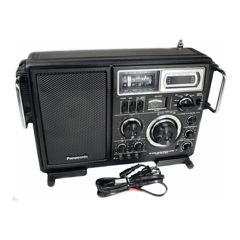
Panasonic RF-1115 User manual

ORDER
NO.
RD7609-1305
ee
ens
Batteries)
Panasonic
UM-2
or
equivalent
Power
Consumption:
7W
at
120V
(AC
Only)
Speaker:
ee
10
cm
(4’’)
PM
Dynamic
Speaker
|
—M
(UHF,
PSB
40.
7
MHz
Dimensions:
i
ae
Wide)
x
632"
(High)x
.
8
a
_.
AM
455
kHz
:
See.
F
-
3"'(Deep)
|
sy!
Bg:
Bpsane
Me
ye
.
Sensitivity:
|
~—~*-UHF
24V
for
S/N
6
db
dar
eet
2h
lB
BO
gis
x
tia
ee
mm)
i
Oe
PSB
2uV
for
S/N
6
db
Weight:
_
5
Ib.
1
02.
(2.27
kg)
with
batteries
FM
1zV
for
S/N
6
db
Impedance:
SDCAKE!,
sishiausdi
aiedtesdnriages
(OR
AM
30zV/m
for
50mW
Output
|
EACDPNONG
JACK,
si
belscias
rietena
00
Power
Source:
AC
120V
60
Hz
|
Recording
Out
Jack
............20kQ
6V
(Four
‘‘C”’
Size
Flashlight
Weights
and
dimensions
shown
are
approximate.
Les
poids
et
dimensions.
mentionnés
sont
approximatifs.
Specifications
are
subject
to
change
without
notice
for
further
improvement.

a
19,
REMOVE
CHASES
3
open
the
battery
«
cover.
;
:
Remove:
the
six
(6)
sro
oe
1~6)
f
for
the
cabinet
back
cover,
as.
shown
|
in
fig.
Ae
.
Remove
cabinet
back
cover.
.
Pull
out
sockets
from
chassis.
_
5.
Remove
the
three
(3).
‘ef
SGIeWS
(nos.
1-~~3)
for
the
chassis,
as
_shown
in
fig.
2.
ce
.
Unsolder
lead
wire.
(for
the
oe
cker)
from
chassis.
.
To
remove
chassis
completely
unsolder
lead
wires
from
cabinet.
so
reassemple,
evelse
ine
above
procedure.
1D
=
To
REMOVE
DIAL
DRIVE
ASSEMBLY
eS
Remove
chassis
from
cabinet.
(Refer
to
chassis
removal
instruc-
tion.)
.
Turn
tuning
shat
fille
counter-
clockwise.
3.
Remove
band
indicator
and
indicating
plate,
as
shown
in
fig.
3.
ee
Remove
the
two
(2)
screws
(nos.
2
&
3)
for
switch,
as
shown
in
fig.
3.
-
Remove
t
the
four
(4)
nuts
S
(10s:
1,4,5
&
6)
for
volume,
as
shown
in
fig.
3.
|
Remove
‘the.
six
(6)
screws
(nos.
2,
3,
4,
5,
8
&
2
for
diay
drive
assembly,
as
shown
in
fig.
4.
2
fig.
4.
:
-
Remove
dial
drive
gecerbly
from
hace
_
ings:
—
A,
Set
variable
capacitors
to
maximum
capacity.
:
2.
Turn
tuning
shaft
fulley
counter-
-clockwise.
o
DIAL
SCALE
INSTALLATION
GUIDE
|.
Turn
tuning
shaft
fulley
counter-
elec
ce.
2.
Loosen
the
two
(2)
screws
(nos.
1
&
6)
for
the
gear,
as
shown
in
fig.
4.
3.
Remove
spring
for
the
rollers,
as
shown
in
fig.
5.
ed
Insert
the
protuberance
of
gear
in
the
catch
no.
1
of
roller
no.
2,
as
shown
in
fig.
6.
5.
Turn
the
gear
one
turn
in
the
direction
of
arrow,
then
attach
the
stopper
to
the
catch
no.
2
on
the
roller
no.
2,
as
shown
in
fig.
6.
6.
Set
roller
no.
1
at
the
position
as
shown
in
fig.
5.
.
Wind
the
dial
scale
onto
the
roller
No.
2,
and
set
it
to
the
dial
drive
““*
assembly.
.
Set
spring
at
the
position
as
shown
in
fig.
5.
.
Hook
the
dial
scale
on
the
boss
of
the
roller
no.
1,
as
shown
in
fig.
10.
Confirm
that
the
SDpBer
of
the
gear
should
be
located
at
the
position,
as
shown
in
fig.
5.
|
11.
Set
start
point
of
dial
scale
at
the
position,
as
shown
in
fig.
7.
12.
ger
the
two
>
(2)
screws
(nos.
1
&
6)
for
the
gear,
as
shown
in
fig
4.
re
:
—
o.oo
Protuberance
—)
Spring
a:
ee
aah
tes
3
:
:
:
Z|
Roller
No.2
2
3
i
:
Sit
Catch
No.1
2
=
Ml
:
2
=
|
Catch
No.2
3
=
Z Z
=
haa]
RollerNo2:
0...
Seale
Stopper
Fig.
6
|
A2
RF-1115
/o
a
Loosen
the
two.
2)
Screws
(nos.
7
&
9)
for
UHF
tuner,
as
shown
in
10
reassemble,
reverse
the
above
Po
and
note
the
follow:
Gear
yom“
ee
-
-ScrewNo.3
(XTB3+45Bi
“Serew
No:1
Screw
No.2
-—(XTB3-F45BFN)
—
(XTB3-£488FN)
see
COW
No.6
o
(XTB3+45BFN).
Screw
Noo.
ots
(XTB3-+408FN)
a
Fig.
A
—(XTB3+458FN)
Red
Screw
No.1
Red
Screw
N
(XTN3+12CR)
Red
Screw
No.2
oe
OS
en)
:
~OCTNG-HI6CR)
roe
~~
ScerewNo.3
NutNot
Screw
No.2
(XTW3+10F)
(XNS8)
_
(XTW3+10F)
Band
Indicator
:
ooo
Nut
No.6s.
(XNS8)
|
(XNS8)
me
(XNS8)
Bo
Fig.
3
Screw
No.5
(XTN3-+
100)
Screw
No.1
Screw
No.2
Shrew
No.3
.
Screw
No.4
(XXARSH6S).-
(XTW3+10F)
(XTW3-+10F):(XTW3-++10F)
:
/
:
Screw
No.8
Sarew
No.9.
Screw
No,10:°
(XTN3+
100)
(XXAR3H6S)
(XTN3+
100)
Screw
No.6.
Sorew
No.7
(XXAR3H6S)
(XXAR3H6S)
Fig.
4
~~
Start
Point
1
Mi
Boss
NO

MI
ALIGNMENT
INSTRUCTIONS
HI
DIAL
CORD
INSTALLATION
GUIDE
READ
CAREFULLY
BEFORE
ATTEMPTING
ALIGNMENT
1.
Remove
dial
drive
assembly.
(Refer
to
dial
assembly
removal
Pulley
instruction.)
|
Pulley
Notes:
|
| _
4,
Set
power
switch
to
ON.
2.
Remove
dial
drum
stopper,
as
shown
in
fig.
8.
Spring
Orum
~
1.
Set
volume
control
to
maximum.
5.
Set
AFC
switch
to
OFF.
(FM-IF
&
RF).
3.
Set
each
dial
drum
at
the
position,
as
shown
in
fig.
8.
3
Goh
iend.
canola
eule:
Beet
cae
cure
ie
1
be:
Se
a
ee
eee
ue
cremen
de
sNownnneles®.
ste
3.
Set
band
selector
switch
to
AM,
FM,
PSB
or
UHF.
7.
Set
squelch
control
to
OFF.
5.
Cord
length
is
140
cm
(553’’).
:
|
6
.
Arrows
(1~13)
indicate
correct
order
and
direction
of
cord
installation.
|
°
7
.
Cement
cord
ends.
2
2
ee
|
4
8.
Mount
dial
drive
assembly
to
chassis.
(Refer
to
dial
drive
—
assembly
removal
instruction.)
bes
|
aoa
9.
Turn
tuning
shaft
fulley
counter-clockwise.
10.
Mount
dial
drum
stopper
at
the
position,
as
shown
in
fig.
8.
11.
Set
start
point
of
dial
scale
to
boss
of
dial
drive
assembly.
(Refer
to
dial
scale
installation
guide.)
7 : |
~]
Hole
ALIGNMENT
POINT
:
106MHz
FMOSC
C33
9O0MHz
ere
ge
CT
L
P
@
me
mz
uae
F
H
9
Pa
some
(R7)
.
bir
-
COMBE:
.
MHz
T0eMHs
PSB
TUNING
AM
OSC
550kHz
|
168MH
ec
1500kHz
=
PSBOSC
PSBIst
;
foal
[TP3}
(Re)
S
eh
ta)
=
=
FM
2nd
pte
z
10.7MHz
Fig.
10
|
P
.
To
SG
To
Receiver
(SG
imp.
500)
be
a
ee
a
ee
Se
=)
zs
Fig.
11
FM
Dummy
Antenna
~ | |
Fig.
12
M@
TUNE/BATT
METER
ADJUSTMENT
1.
RADIO
RECEIVER
SETTING
.
2.
REMARKS
»
Set
band
switch
to
AM.
|
-«
Adjust
Rso
so
that
the
pointer
of
-
Set
volume
control
to
minimum.
meter
stays
as
shown
in
figure
-
Set
power
source
voltage
to
6
volts
DC.
_at
right.
.
A
3
.
RF-1115
/o
|
SIGNAL
GENERATOR
or
RADIO
DIAL
INDICATOR
SWEEP
GENERATOR
|
L
SATOR.
|
CONNECTIONS
|
FREQUENCY
(DISTANCE)
|
(VTVM
or
SCOPE}
ADSUSTMENT
eREMARKS
AM
ALIGNMENT
Fashion
loop
of
|
“Point
of
non-
|
.
tee
| |
(1)
ele
ae
of
ae
Bt
hes
|
interference.
|.
al
dak
meter
Tee
AGT)
Adjust
for
maximum
and
radiate
signa
_
into
loop
of
receiver.
|
With
400
Hz.
eo
ne)
.
voice
coil.
Tr
(2nd
IFT)
ahs
ake
_AM-
RF
ALIGNMENT
: |
L10
(OSC
Coil)
Adjust
for
maximum
|
,
|
350
kHz
output.
Adjust
L11
by
(2)
,
950
kHz
7
|
4,
|
Moving
coil
bobbin
a
:
—
Ces
(OSC
7
3
|
fecoLae
1500
kHz
|
ey
jIrimmer)
Adjust
for
maximum
Ces
(AN
output.
Repeat
steps
(Fig.
14]
TrARSE)
(2)
and
(3)
—(*)
Gement
antenna
bobbin
with
wax
after
completing
alignment.
FM-IF
ALIGNMENT
;
Connect
vert.
a
|
Oar
te
aint
{TPA
10.7
MHz
Pclnt
ornon
amp.
of
scope
to
|
Ts
(FM
1st
IFT)
|
Adjust
for
maximum
(4)
Negative
side
to
|
(on/about
point
[TPs]
(*)
|
Ts
(FM
2nd
IFT)
|
amplitude.
earth.
?
SWP.
90
MHz).
Negative
side
to
(Primary)
(Refer
to
fig.
9).
PSB-IF
ALIGNMENT
Connect
vert.
amp.
of
scope
to
Adjust
for
maximum
on
Ww
point[TPe]
Ta
(PSB
1st
IFT)
|
amplitude.
eee
side
to
(Refer
to
fig.
9).
UHF-IF
ALIGNMENT
7
Connect
vert.
—
High
side
thru.
f
amp.
or
pore
to
Adjust
for
maximum
(6)|
0.0014F
to
point[TPs]
point|TPel
T:
(UHF
1st
IFT)
|
amplitude.
Negative
side
to
:
Negative
side
to
(Refer
to
fig.
9).
earth.
earth.
FM-IF
ALIGNMENT
High
side
thru.
=m
emp
oLscone
to
Adjust
for
maximum
0.0014F
to
point[TP4|
:
To
(FM
2nd
IFT)
:
:
Negative
side
to
(Refer
to
fig.
10).
earth.
_
a
earth.
an
High
side
thru.
!
0.001
uF
to
point
[TPs]
"
Negative
side
to
.
FM-
RF
ALIGNMENT
Connect
to
point[TP1|
through
FM
dummy
| |
(8)
ane:
Negative
eer
:
ie
(F
side
to
ear
ig.
|
coil.
(Refer
to
fig.
11).
oie
Tuning
Coil)
106
MH
isi
rt
tian
)
|
(
.
Zz
rimmer
+)
Adjust
for
106
MHz
‘Fig.
16)
|
“
C33
(FM
Tuning
maximum
output.
:
Trimmer)
,
3
PSB-RF
ALIGNMENT
140
MHz
168
MHz
:
Output
meter
90
MHz
~
across
voice
M
OSC
Coil)
|
(*)
Adjust
for
M
-maximum
output.
L7
(PSB
P
eo
Coil)
|
(*)
Adjust
for
,
Ls
(PSB
maximum
output.
[Fig.
171
Tuning
Coil)
Cag
(PSB
OSC
|
-
pe
Trimmer)
|
(*)
Adjust
for
C30
(PSB
Tuning
maximum
output.
|
Trimmer)
¥
168
MHz
—
°
(Fig.
18)
*«
Three
output
responses
will
be
present;
proper
tuning
is
the
center
pocccney:
RF-1115/6
|
|
A4

HI
CHASSIS
PARTS
LOCATIONS
PSB
FM
AM
CH4
CHi0
PSBHIGH
136~174
|
UHFE
450-512.
AM
525~1605°
FM
88~108
AM
525~1605
FM
88~198
|
I
|
2
Miz
KHz
Fig.
15
140
MHz)
(
Fig.
17
90
MHz)
(
13
(550
kHz)
e
ig
F
PSBHIGH
136~174
UHF
450
~512
AM
§25~1605
FM
88~108
WTUTERUCELER
TUE
CULE
LE
MHz
Miz
SCALE
kHz
MHz
106
MHz
Hz
CHa
“S11~Sts
Fig.
18
(168
MHz)
)
1
s
*
Fig
14
(1500
kHz)
”
Fig
H
CABINET
PARTS
LOCATION
ylene
Bag
(XZB10X25A04)
Polyeth
"
Pad
3
(RPN2253Z)
af
)
A6
vos
Pad...
(RPN2252Z)
(RPK452Z—for
USA)
(RPK452Y
Gift
Box
Polyethylene
Cover
(XZB40X30A04)
Hi
PACKING
MATERIALS
AND
ACCESSORIES.
19
F
7
CA
ee
ee
eS
eS
oo
et
og
me
*,
IIIS
IT
PP
f
Bririss
ae
eae
Ld
alk
”
age
re
seca
ae,
“5
PAP
tds
OFT
ee
ed
ee
PELE
hl
Sod
tod
fod
ok
ded
Sod
Fed
Fed
Fed
Fak
dd
bd
Ph
Pe
ee
ag
ee
ae
iy
ay
Oe
ae
ae gg
ay
og
ay
Oe
ie
Oe
et
PATA
LF
Sod
Ued
ok
Seok
Pad
Tod
Bod
Dod
Sod
dnd
dodedadednfded-Anbopohabedpifed
PS
Sd
deal
Dod
dod
Pad
ek
Ded
Dod
Dod
Bed
dato
cdr
dnc
Peja
dehadeded
POPE
ET
LT
LT
BS
ted
hd
Pd
Oe
ed
Ded
Pd
dete
dedaded
Soddwted
Betta
tata
ete
hae
ee
eg
a
Be
ee
afte
pte
te
Be
hae
Ee
a
ee
i
2
eee
eee
ae
Oe
ee
ee
ee
Pk
ok
Fd
Fd
Fd
eC
P
bed
bok
hd
ok
ted
Sol
Toll
tok
tok
bo
Fad
an
Sa
i
Ma
he
a
a
Ne
ae
oe
PE
LPs
[od
Jaf
J
6
C
8
A
C
CAN
—
for
Canada
1g.
RF-1115
/o
RF-1115
/o
A5

BEREPLACEMENT
PARTS
LIST
--+-+-+-++++2+++++++++
Model
RF-1115
(RD7609-1305)
ee
RLI2M402
RLI4M504
RLI4M507
RLT3F30-V
d.
IFT,
AM
2nd
IFT,
FM
2nd(Primary)
IFT,
FM
2nd(Secondary)
Input
Transformer,
P=1K02:S=7000
Output
Transformer,
9}
NOTES:
1.Part
numbers
are
indicated
on
most
mechanical
parts.
Please
use
this
part
number
for
parts
orders.
2.Components
identified
by
shaded
area
have
special
characteristic
important
for
safety.
When
replacing
any
of
these
components
use
RLT2G22-W
only
manufacture’s
specified
parts.
3.Part
numbers
shown
in
bold
letters
are
service
standard
parts
and
may
differ
from
production
parts.
4.The
O
mark
is
used
by
the
manufacturing
plant
only.
[_Renarks
|]
2KQ(B),
Squelch
&
Tone
Control
5OKQ(D),
Volume
Control
2K0(B),
Preset,
Meter
Control
BVH5SXAO026B23
HVH5XA0Z2Z6D54
EVLTOAAOOB
23
INTEGRATED
CIRCUIT,
TRANSISTORS
AND
DIODES
VARIABLE
CAPACITORS
IC,
FM/AM
IF
Amp.,
AM
Converter
Transistor
(Ge),
UHF
IF
Amp.,
PSB
RF
Amp.,
FM
RE
Amp.,
FM
Converter,
FM
1F
Amp.
IC
RVIUPC1018CE
TR3,4,6,7,8
25A838
Tuning
Capacitor,
W/Trimmer
Capacitor
(C33,52,64,65)
Trimmer
Capacitor
C31,34,48,51,|
RCV2X4216TL
62,63
C30,49
HCVIZW10XS32
O/
SLLL-4Y
TR5
TR9,11
TR1O
TR12,14
TR13
TR15,16
D2,4,7,10,11,
2901674
25A564
28C828
29B173
280945
2801383
OA90
RVDSD113
RVDMZ204C
RVDVD1250L
2-OA90
RVDVD1250M
RVDVD1150M
RVF1O7MFB
RLD4N35-0
RLD4N30
RLO4N92-0
RLO4N54
RLO2M15-K
Oscillator
Coil,
AM
ERD25TJ470
470,
%Watt,
ERD25TJ681
6800,
%Watt,
+5%,
Carbon
RLF2F151-0
RLI4M101
RLI4M103
RLI?7W105-2
Transistor(Si),
PSB
Converter
Transistor(Ge),
DC,
Squelch
Amp.
Transistor(Si),
Meter
Amp.
Transistor(Si),
AF
Amp.
Transistor(Si),
AF
Amp.
Transistor(Si),
Power
Amp.
Diode
(Ge),
PSB
AGC,
PSB-FM
AGC
AM
Detector
&
AGC,
FM
AGC,
Rect.
Diode
(Si),
FM
AFC
Diode
(Si),
Operation
Compensator
Diode
(Si),
Operation
Compensator,
Rectifier
Diode
(Ge),
FM
Detector
Diode
(Si),
Operation
Compensator
Diode(Si),
Power
Operation
Ceramic
Filter
Coil,
PSB
Tuning
Coil,
FM
Tuning
Oscillator
Coil,
PSB
Oscillator
Coil,
FM
Antenna
Coil,
AM
IFT,
UHF,
PSB
&
FM
IFT,
PSB
&
FM
IFT,
AM
lst
OnkrnworvNEH
MoMA
HHHP
RPP
Hw
ERD25TJ104
ERD25TJ470
ERD25TJ103
RXABPF174021
RXABPF10801H
RXAF1O3P22HD
RSR4F012-H
RSTX0012Z-M
COMPONENT
COMBINATIONS
470,
10KQ,
Component
Combination,
Coils
&
Capacitors
Component
Combination,
Coils
&
Capacitors
Component
Combination,
O0.0luF
x2
Speaker,
Imp.16N,
10cm(4”),
PM
Dynamic
SPEAKER
Switch,
Band
Switch,
Power,
FM
AFC
&
Loudness
100KN,
%Watt,
2eWatt,
4Watt,
+5%,
Carbon
+5%,
Carbon
+5%,
Carbon
+5%,
Carbon
A&R

O/GtLt-du
ERD25TJ332
ERD25TJ332
ERD25TJ102
ERD25TJ102
ERD25TJ331
ERD25TJ471
ERD25TJ470
ERD25TJ470
ERD25TJ152
ERD25TJ681
ERD25TJ224
ERD251TJ334
ERD25TJ680
ERD25TJ470
ERD25TJ104
ERD25TJ470
ERD25TJ220
ERD25TJ470
ERD25TJ103
ERD25TJ331
ERD25TJ224
ERD257TJ331
ERD25TJ682
ERD25TJ102
ERD25TJ102
Watt,
+5%,
Carbon
ECKE1H102MD
ERD25TJ153
2Watt,
+5%,
Carbon
ECKD1H102PF
5OWV.
+209
q
ERD25TJ223
“Watt,
+5%,
Carbon
ECKD1H102PF
5OWV,+2°S%,
ECCD1H1O00KC
5OWV,+10%,
ERD25TJ222
ERD25TJ154
ERD25TJ222
ERD25TJ823
,
*Watt,
,
+*Watt,
“Watt,
Watt,
%Watt,
Watt,
Watt,
Watt,
,
*Watt,
Watt,
,
4Watt,
,
*Watt,
Watt,
“Watt,
,
Watt,
26Watt,
2eWatt,
%
Watt,
“Watt,
Watt,
,
*Watt,
2Watt,
,
*Watt,
24Watt,
,
4Watt,
,
BWatt,
,
%Watt,
Watt,
—Remerke
__|
£5%,
Carbon
+5%,
Carbon
£5%,
Carbon
+5%,
Carbon
+5%,
Carbon
+5%,
Carbon
+5%,
Carbon
+5%,
Carbon
+5%,
Carbon
+5%,
Carbon
+5%,
Carbon
+5%,
Carbon
+5%,
Carbon
+5%,
Carbon
+5%,
Carbon
+5%,
Carbon
+5%,
Carbon
+5%,
Carbon
+5%,
Carbon
+5%,
Carbon
+5%,
Carbon
+5%,
Carbon
+t5%,
Carbon
ERD25TJ472
,
4%Watt,
+5%,
Carbon
ERD25TJ100
,
£5%,
Carbon
ERD25TJ150
2eWatt,
+5%,
Carbon
ERD25TJ470
2gWatt,
£5%,
Carbon
ERD25TJ103
Watt,
+5%,
Carbon
ERD25TJ122
,
*Watt,
+5%,
Carbon
Pp
apacirorsS
ERD25TJ470
Watt,
+5%,
Carbon
ERD25TJ470
2Watt,
+5%,
Carbon
ECQG05333MZ
5OWV,+20%,
ERD25TJ103
,
4Watt,
5%,
Carbon
ECKD1H102PF
5OWV,+7°3
%,
ERD25TJ332
,
4Watt,
5%,
Carbon
BCKE1H103MD
5OWV,+20%,
ERD25TJ1i02
4%Watt,
+5%,
Carbon
ECKD1H102PF
5OWV,47°S%,
ERD25TJ102
2eWatt,
+5%,
Carbon
ECKE1H103PF
5OWV,+7°S%,
ERD25TJ102
zeWatt,
+5%,
Carbon
EHCKE1LH1O3PF
5OWV,+7°S
%,
ERD25TJ104
,
*Watt,
£+5%,
Carbon
HCKE1H103PF
SOWV,
+
*°S%,
BCKE1H103MD
5OWV,+
20%,
+5%,
Carbon
+5%,
Carbon
+5%,
Carbon
+5%,
Carbon
+5%,
Carbon
pela
+5%,
Carbon
,
£5%,
Carbon
,
£5%,
Carbon
,
£5%,
Carbon
ERD25TJ151
ERD25TJ220
ERD25TJ471
ERD25TJ333
ERX1ANJR47
ERD25TJ473
ERX2ANJ100
ERD25TJ470
ERD25TJ102
ERD25TJ223
ERD257J472
ERD25TJ681
ERD25TJ823
ERD25TJ122
ERD25TJ470
ERD25TJ223
ERD25TJ472
ERD25TJ470
ERD25TJ471
ERD25TJ680
ERD25TJ470
ERD25TJ222
ERD25TJ390
£5
%,
Carbon
+5%,
Carbon
,
£5%,
Carbon
,
£5%,
Carbon
,
£5%,
Carbon
,
+5%,
Carbon
,
£5%,
Carbon
,
&5%,
Carbon
,
£5%,
Carbon
,
£5%,
Carbon
,+5%,
Carbon
,
£5%,
Carbon
,
£5%,
Carbon
,
©5%,
Carbon
,
5%,
Carbon
,
+5%,
Carbon
,
£5%,
Carbon
;
i
1
i
1
1
1
1
1
1
1
al
1
1
1
1
al
1
a!
al
1
1
1
HCCDLH180KC
BHCCD1HO040C
ECCDIH3R5C
50WV,+0.25PF
Ceramic
5OWV,+0.25PF
Ceramic
ECKE1H103PF
O.01uF,
S50OWV,+7*°S%,
Ceramic
ERD25TJ221
f,
%Watt,
£5%,
Carbon
ERD25TJ331
,
%4Watt,
+5%,
Carbon
HCKB1HiO3SPF
0.01
uF,
BOWV,+7°S%,
Ceramic
ERD25TJ272
,
+*Watt,
+5%,
Carbon
BCCDIH220KC
22PR
5OWV,+10%,
Ceramic
ERD25TJ334
,
4Watt,
+5%,
Carbon
HCCD1LH330KC
35PF,
5OWV,+10%,
Ceramic
ERD25TJ221
,
Watt,
t5%,
Carbon
BCCD1HO50CC
5PF
50WV,+0.25PF
Ceramic
ERD25TJ152
.
4Watt,
+5%,
Carbon
ECKE1H223PF
0.0224F
5SOWV,t7°8%,
Ceramic
ERD25TJ103
,
2Watt,
+5%,
Carbon
BCCD1HO70DC
7PR,
5OWV,t0O.5PF
Ceramic
ERD25TJ223
,
%Watt,
+5%,
Carbon
ECKE1H103PF
0.01
“nF,
5OWV,+7°S%,
Ceramic
ERD25TJ824
,
*Watt,
+5%,
Carbon
ECCD1H120KC
12PF,
5OWV,£10%,
Ceramic
ECCD1HO30C
SPF,
5OWV,+0.25PP,Ceramic
ERD25TJ222
:
,
%*Watt,
+5%,
Carbon
ERD25TJ330
;
*%Watt,
£5%,
Carbon
ERD25TJ153
,
4%Watt,
+5%,
Carbon
ERD25TJ330
:
Watt,
+5%,
Carbon
HCKD1H102PF
BCKD1H102PF
ECEA10V1000
0.001lxF
50WV,t7°S%,
Ceramic
O.001uF,
50WV,+7°8%,
Ceramic
1000znF,
10WV,
Electrolytic
PREP
RP
EY
PEP
PP
PRP
ERP
PP
RP
EP
PEPE
PE
REPRE
RP EP EP
PRP
PRB
PPP
Pe
EP
ee
eee
Pe
ee
Pe ee
eB
ae
4
~A10

O/SLLL-AW
BHCHAS5SOVILB
BCKT1H103MD
ECCD1H100KC
ECKT1H103MD
ECEA10V100
BHCQS13015Z
FCQG05333MZ
BHCHA16V10B
BCHA6V47B
HCOKEH1H223MD
HOKELH223MD
ECCD1LH101K
BCKEH1H1O3MD
BCHA6V47B
HCKT1H103MD
BECKE1LH103MD
BCFVD333MDY
ECEA50ZR22
ECEASOZR22
BCHA5OVILB
ECEASOV1
ECKE1H103MD
BHCKE1H103MD
BCHAS5SOV1B
BOPTD333MDY
HCKE1H103MD
BHCKE1H682MD
HCKE1H152MD
ECEA50ZR47B
ECFVD333MDY
ECEA6V470
ECKT1H1O3MD
ECEA50ZR47
BCHA5SOZR47B
BCBA6V47B
ECKT1H1O3MD
BCFTD223MDY
BHCFVD2235MDY
BCHA50ZR1B
ECEA10V
2200
ECEA6V470
ECEA16V10
HCBA6V47B
ECKE1H103PF
BECKBH1H103MD
HCCT1IHI81K
ECCD1H181K
ECFVD1LOSMDY
BCCD1H101K
BHCKE1H223MD
ECKT1H1035MD
BHCCD1H331K
ECKE1H103MD
ECKE1H103PF
HCFVDLOSMDY
BECKD1H102PF
ECKD1H102MDA
Lyk,
0.01
nF,
10PF,
0.0L
BE,
100
nF,
Z00PF,
|
0.033
4F,
LO
uF,
47
uF,
0.022
uF,
0.022
uF,
1O0PF,
0.01
uF,
47
uP
0.01
uF,
0.01
uF,
0.033
uF,
O.22¢uP,
0.22
uF,
Lyk,
Lyk,
0.01
uF,
0.01
uP,
LyuF,
0.033
uF,
0.01
uF
0.0068
uF,
0.0015
nF,
O47
uF,
0.033
uF,
470
uF,
0.01
uF,
0.4'7
uF’,
0.47
nF
47
uP,
0.01
uF,
0.022
uF,
0.022
4F,
O.1
uF,
2200
uF,
470
uF,
10
uF,
4.7
uF,
0.01
nF,
0.01
uF
180PF,
180PF,
0.001
uF,
0.01
uF,
100PF,
0.022
uF,
0.01
uF,
SOOPER
0.01
uF,
0.01
uF,
0.0L
yF,
0,001
uF
SOWV,
Blectrolytic
5O0WV,t20%,
Ceramic
5OWV,+10%,
Ceramic
5OWV,+20%,
Ceramic
LOWY,
Blectrolytic
125
WV,+5%,
Styrol
5OWV,+20%,
Polyester
1L6WV,
Hlectrolytic
6.3WV,
Electrolytic
5OWV,+20%,
Ceramic
5OWV,+20%,
Ceramic
5OWV,+10%,
Ceramic
5OWV,+20%,
Ceramic
6.3WV,
Electrolytic
50WV,+20%,
Ceramic
5OWV,+20%,
Ceramic
2Z5WV,+20%,
Semi-Conductor
5OWV,
Electrolytic
5OWV,
Electrolytic
5OWV,
Blectrolytic
5OWV,
Electrolytic
5OWV,+20%,
Ceramic
5OWV,+20%,
Ceramic
5OWV,
Electrolytic
25WV,+20%,
Semi-Conductor
5OWV,+20%,
Ceramic
5OWV,+20%,
Ceramic
5OWV,t20%,
Ceramic
SOW,
Electrolytic
25WV,+20%,
Semi-Conductor
6.3WV,
Hilectrolytic
5OWV,+20%,
Ceramic
5OWV,
Hiectrolytic
5OWV,
Electrolytic
6.3WV,
Electrolytic
5OWV,t20%,
Ceramic
25WV,+20%,
Semi-Conductor
2Z5WV,£20%,
Semi-Conductor
5OWV,
Electrolytic
10WV,
Electrolytic
6.3WV,
Hlectrolytic
16WV,
Hiectrolytic
6.3WV,
Blectrolytic
5OWV,+7°8%,
Ceramic
5OWV,+20%,
Ceramic
5OWV,+10%,
Ceramic
5OWV,t10%,
Ceramic
5OWV,+20%,
Ceramic
ROWV,+20%,
Semi-Conductor
5OWV,+10%,
Ceramic
5OWV,+20%,
Ceramic
5OWV,t+20%,
Ceramic
5OWV,+10%,
Ceramic
5OWV,+20%,
Ceramic
5OWV,+7°S8%,
Ceramic
25WV,+20%,
Semi-Conductor
5OWV,+7°38%,
Ceramic
Ne
ee
ee
eee
eee
eee
eee
ee
ee
ee
ce
cele
cele
cell
ool
ell
ll
oll
ool
ell
ool ool
el
el
|
Remarks
_|
Part
Name
&
Description
eee
Remarks
#0
HCKD2H103PE
ECEA16V10
BCKE1H1O3MD
ECCD1H331K
BCQG05473MZ
BHCCD1H331K
ECCD1H101K
ECCD1H103MD
BCKE1H102MD
BCCD1H331K
HCCD1H331K
BCKD2H103PE
ECKD2H103PE
ECKE1H103MD
BCKEH1H1IO3MD
HCKE1H103MD
BHCQG05473MZ
ECCD1H120KC
ECKE1H1i03MD
ECCD1HO50CC
ECCD1H040C
ECKD1LH102MDA
BCKE1LH103MD
ECEA1I6V33
BCCD1H120KC
ECEA6V220
RYMF1115M
RKX1182Z
RYFF1115M
RJC6034
RJC205B
RKK1122
RBN3582Z
RBN3592Z
RBS1062
XTB3+45BFN
RJJ10C
XEARR174GDSN
0.01
nF,
10
uF,
0.01
uF,
330PF,
330PH,
100PF,
0.01PF,
330PF,
330PPF,
0.01
uF,
0.01
yF,
0.0L
uF
0.01
uF,
0.01
pF,
12PF,
0.01
uF
5PF,
4PR
0.01
uF,
SS
uF,
LePH,
220
uF,
Handle
1080mm
RYDF1115M
RDZO51-1
RKD403Y
RDS40622
RXHF1115M
XAMR57S150
REM261
Z-
0.047
uF,
0.001
uF
0.04.7
uF,
0.001
nF,
CABINET
CHASSIS
Jack,
Earphone
&
Rec.
Out
Part
Name
&
Description
e{—
1OOWV,+2°38%,
Ceramic
16WV,
Hlectrolytic
5OWV,+20%,
Ceramic
5OWV,+10%,
Ceramic
5OWV,t20%,
Polyester
5OWV,t10%,
Ceramic
5OWV,+10%,
Ceramic
5OWV,t10%,
Ceramic
5OWV,+20%,
Ceramic
5OWV,£10%,
Ceramic
5OWV,£10%,
Ceramic
LOOWV,+1°S%,
Ceramic
LOOWV,+?°8%,
Ceramic
5OWV,+20%,
Ceramic
5OWV,+20%,
Ceramic
5OWV,+20%,
Ceramic
5OWV,+20%,
Polyester
5OWV,+10%,
Ceramic
5OWV,+20%,
Ceramic
5OWV,+0.25PE
Ceramic
5OWV,+0.25PFCeramic
BOWV,+20%,
Ceramic
5OWV,£20%,
Ceramic
16WV,
Electrolytic
5OWV,+10%,
Ceramic
6.3WV,
Blectrolytic
PREP
PHP
HPP
YEP
ee
EP RB
EP
PP
RB
PP
Ee
ee
Pe
PR
Cabinet
Assembly
Cabinet
Back
Cover
Assembly
Terminal
Spring,
Battery
©
Side
Terminal,
Battery
©
Side
Cover,
Battery
Compartment
Telescopic
Antenna,
7
Steps,
Knob,
Tone
&
Volume
Knob,
Tuning
Knob,
Band
&
Squelch
Screw,
Cabinet
Back
Cover
M’tg
Jack,
Loop
Antenna
Dial
Assembly
Cord(500m),
Dial
Scale,
Dial
Spring,
Dial
Indicating
Plate
Assembly
Pilot
Lamp,
Dial
M
T
&
Batt
O00
ee
eC
ee
ol
HONE
dW
A19

O/SLLL-AY
|
secon
a
|
Betsy
Tun
be:
cece
ede
a
XYN26+4+C5
Screw,
Tuner
M’tg
RGX769Z
Indicator,
Band
XEH1A1-
P
|
Magnetic
‘Earphone.
RSA9042
UHF
Antenna
UM-2DE-
(P)
Battery
RQX6023Z
Instruction
Book,
For
U.S.A.
RQX602424
|
Instruction
Book,
For
Canada
A15
:
A14

_o
REC
OUT
_
JACK
EARPHONE
OR
EXT
SPEAKER
JACK
it
Board
Wiring
View-Model
RF-1115
TRiy
TRis
TRia
“TRis,
16
ic
pron
ps
?
|
°
|
1.4Vv
SQUELCH
oe
Tu
Ti
Lis
Lig
Lui
wie
eens
120L0
Ta
Te
Tr
eg-li2
La
Bs
Ta
bis.
bt
bg
oo
To
ee
1
ha
:
'
es
;
4
OV
|
4.6¥
7
i
|
B
|
0.56v
|
owennmeneaneenndeamucimesenentngnnmansnnatrananntn
0.04V
ss
a
en
ar
Tacit
——
eee
caaeias
os
ia}
FM
T
AM
|
[EM
AM
|
FM
AM
2
0.6V
Ov
8
|
3.3Vv
BO
Mis.
daca
=
Ts
—t
)
fe)
OV
9.
OV
OV
ETB
Ov
)
|
|
2.85V
|
OV
tol
ov
/
|
ozaverie
4
: :
r
area
|
"
L
5
3.3V
|
OV
Trp
0
OV
4.5V
:
inf
np
6
4.4v
|.
ov
12)
0V
“4.6V
a
with
bss
cenntenthicesicocs
LAM
ANTENNA
COIL.
TELESCOPIC
ee
:
Ee
a
ee
TUNING
CAPACITOR
W/
TRIMMER
CAPACITOR
‘4°UQcn)
PM
DYNAMIC
-
SPEAKER
an
INDICATOR
|
srg
ssa
|
EXT
POWER
SOURCE
—
JACK
W/AC-BATTERY
SELECTOR
‘BATTERY.
bv
Ci510.01
aS
db00O080
¢
TRD&IC|
TRe
Dia
TRis
Dis
Dig
TRI
TRid
TRi2 TRio
Di
Di2
01307
Dig
IC.
De
Dg
TR3
~~
TRe
Da
~TRT~~—
Dé
Dio
D3
TRe
Ds
D2
TR
TRs
TRE
TR4.
la
Lig
Ti2
D2
ore
oe
es
|
RF-1115/0,
BS
BE
WOOP
ANT
TELESCOPIC
.
ANTENNA
~
;
Rio
10k.
2
TR
oSAig8
2SCib74.
PSB
RF
AMP
UHF
RF
AMP
|
ba.)
162°2
69315045
42
AG.
44:
RF-1115/o
my
C2ki5p
ae
;
*
:
C16
a
Oo
peee
eee
WBS
Rii3.3k
C23:0.01
TRi
:
Ree
4!
2)
OQ
a
:
Vo
aa
S
C230.001
ole
7
oO
=
Px
C37
Rage
ona
ie)
—.
;
a}
=
!
7
w
“asiiga
asin
4
2
2801674
PSB
CONV
Ris
33
Oe
C36
ee
oH
Ry/
vy
2
Re
220K
182791
UHF
TRs
OER
E:
31
28838
2Sh838
—-2SA838
-FMIF
AMP
=~
UHF
IF
AMP
oF
Peed
iMO.Ot
C20
0.001
KH
Ci6l
Re
100k
CroMo.ot
/
C44D7p
sePSB
AGC
10°11
12
415
168
169
160
23
24
25
26
27
28
29
30
3132
333435
36
373839
40414243
444546
151617
18
96
11019
2021
22
~
ov
Ras
47]
__2|
y
Dio
8
Schematic
Diagram-Model
RF-1115
0A90
FM
PSB
AGC
RVIUPC1018CE
FM/AM
IF
AMP
oA
AM
DET
=
AGC.
FM
DET
oste8
Asiboe,,
~
METER
AMP
SQUELCH
AMP
Ms
0Ag0
avovD1250
aed
AVOWEIZSOM
yt
OF
a
oy
eat
Re2
27k
|
R52
221k
+9
ie
aes
lesa
S
Le,
=
ola
Q
On
=|
8
co
ray
Go
8)
32
¢
.
®
a
=
ino)
ee
Ro
n°.
|
|
2
OOK
{
fap)
1
/
se
i
©
Voltage
Line
_
"|
Reaik,
RECOUT-
hye
sours
i
:
EP
8Q
ee
=[o°
8
3
aul
eee
:
oS
!
:
O
3
| |
M
©
=
|
N
pee
a!
Ol
slelserst
[els
i=
<0
!
|
Pla
or
ors"
B8lS].
|
8]
2
ol
3
ET
ee
!
6
rc}
Olé
Bow
a)
oO
A
as
_
!
ts
ior
S|
6bel
=
ats
51
6
S|
tocm(4")
6!
[O__
:
|
=
18
5
0
Gt
eg!
Ol
tke
=
J
T2813
ss
0
aes
.
16
z
CesM10.01
O!
0!
Oo!
SI
Fa
FS
PRGA
ARRON
OB
CE
TER
PET
FEE
ANA
Na
aaa
ae
RE
ag
SNES
1
a
mre
aaa
reacts
wrdlen
Sat
poe
eadrg
ea
iae
gets
am
andr
coas
a
foster
niin
ie
cit
ee
ee
=
a
4
5
TRi3
D15.16
j
0A90
RVDSDI13
0A90
RVDMZ204¢
aVOVD1250
2SN564
2SB173
286949
2$B173
RVDVD1150M
2801383
AVOTOE
ILE
:
FM
AFC
FM
AGC
AOC
AOC
DC
AMP
AF
AMP
AF
AMP
AF
AMP
AOC
POWER
AMP
RECT
ia
{14
15
16
{7
18
(61
154165108
19.
20
21.
10
126
22
116
60
62636465
666768
127
TO
‘7
ube
13
:
7475
76.
ET
oor
a
8111182
3S
84
85
140
BPE
AGEL.
48
49113505152
5455
14256
5756
(17
88
89
106
(46
14590
102
91929394
95
96
97 38
99
«100
101
—
12B
114
144,
{03
129
143
104182
14448
{49
105
{66
3.4
~=6
Pl
Ge]
8
37
38.
99°88:
98
S31O1
40.
42
87
43
44
45 46
474810049
50
51
52
ao
Stee
eee!
59
6061
62|
24
25
26
2792
28
2330
31
32
33
34
353689
6495
65
66
67
68
69
70717297374
818586
75767778
79
101
BO
-
82
83
BS
3
-
oe
3
Cathode
_
Anode
Anod
(<4
A
AN
OC
Cathode
Cathode
&}
|
Cathode
Cathode
ae
Anode
Anode
7
note
|
shee
TR3~
11,13,15,16
D2,4,7,10,11,12
D8,9
D6,13,14,17
»e
a
D)3:5
eels
y |
215,16
BOTTOM
VIEW
000].
omeme)
a
Ut
&
Si-1~S1-6:
Band
switch
in
‘‘UHF’’
position.
‘Sz:
Power
switch
in
“OFF”
position.
Ss:
AFC
switch
in
‘‘ON”’
position.
Sa:
Loudness
switch
in
“‘OFF’’
position.
Ss:
Dial
light
switch
in
‘‘OFF’’
position.
Se:
AC-battery
selector
in
‘‘Battery”’
position.
-DC
voltage
measurements
are
taken
with
circuit
tester
10k9/V
from
negative
terminal
of
battery.
PRise
3c
UHF
position
TRa,
s......
PSB
position
TRs,
7,
8......FM
position
[__]......FM
position
Sy
es
AM
position
uage
oe
ee
Squelch
max
position
8.
Battery
current:
No
signal
................2....
|
Maximum
output
IMPORTANT
SAFETY
NOTICE
THE
SHADED
AREA
ON
THIS
SCHEMATIC
DIAGRAM
INCORPORATES
SPECIAL
FEATURES.
IMPORTANT
FOR
SAFETY.
.
WHEN
SERVICING
IT
IS
ESSENTIAL
THAT
ONLY
MANUFACTURER'S
SPECIFIED
PARTS
BE
USED
FOR
THE
CRITICAL
COMPONENTS
IN
THE
SHADED
AREAS
OF
THE
SCHEMATIC.

‘BundepyeusyoleZ
—
SWeI4
1997
py
WV
UOHeWIOJUT
yonb
pv
/
€
VY
YOHeUUOsU|
uejdsbunwyjipio,
—~mdn—Fiche—Organisation—Form
310
Nach
DIN
19054
(
International,
NMA-Standart
)
98
Nutzenseiten
DIN
A4
(
49
Nutzenseiten
DIN
A3
)

Kopfzeile
je]
(-]i¢s
me
(21
ak
Ge)
9)
74=)|
|=
eee
ee
mer
ere
reer
re
renee
renner
aererre
treet
FURIOS
SI
Ol
NG
ceases
esersone
teestcnecnrontcectey
tee
ucomessemeunieanesste
esas:
[alate]
ite
(=1ah
a)
6)
4
=)|
(=
eure
ennee
emeree
ne
re
tenere
ecterirey
Se
neerererrer
preter
reenact
str
eseeoesveeveeeseeeaeeaeeeaeeosevevodces
@ee¢eeeoeeseaeeseeseeaeeoeeeevecnenase
Seeeseeseooeaseeaeseeeneeseeeoeeoeceaones
SHCOHHSHTEOSEEESEOOCEEEOEHOESEEEOCS
eeseeaeeeneeeceesaeceaeesegeaeeneoeegnesesd
@eseseeeesensesvnseossaeseseseeeeeeve
ne
@eeoaeeceoeeeeeesnseonsaceceseeove_ens
*eseeeeeoeceseeeeeoeoeseeoenenseaeanerse
SeeeooeoeCeoseaeeeseseeeeseoaeeseoeeeeos
ve
Peeoeeeesesseaeeeeseesvsesevseseseseeoe
Seceoeseeseeeeeeonseseaenaeeeeenanene
POSS
SHSSHHESERDERHESEESHEEHHHHTEEHREHOE
Peeeeeeeoeoesseeooeaeseeeseaeseeeve
Geese
eeseeosHeeaaesvesevesvaeneeed
Seeeeeseeevesv
eee
eooeseoeeseevoat
et
esd
@eteeeceoeosceseseovneeseneseaeeaneeeonens
@aeeese
Cososeeeoseceneeoeoseoeveneeevee
eesevoseneeoeeoeoeoeoaseeaeeeeeoeoeseeceeos
Seevoeaetasevoeseeseeeeoenseneaeeenrne
—
Seeeeee
Ree
oer
eseeseooeeoseeaearsee
een
@@*#eooeoeeeoeascetetoseseeoeseeesaesecaeene
seespeeoeoeoe
se
etteesecesaesaeeoeece
@eeceeseeoeseecoooaseseaeseeeveaeses
eee
Peeeeesetreseeaseaeoeenaeeseseneaens
@eseaeeeeeesestescescecoenreecesnseaetene
Pe
eeeeCeeeaeceaeseseneseooeeeaaeeeee
S#eseoevoaeseeeeeaeeoee
nb
aeresconeneeee
eeeeoeeeeeeeoaeeeseeevesseeeeeaee
@eeeeeaoeoeseeeeeseoeeeeecaaaesaeoneaea
SBeeeeseeseeoe
ees
eseeeseeeeeeeoeeeeeoe
Peeeeeeseseseseeeseeaesseseseeseeeeeoeovgcezes
SeCeeoeeveeoseeseecoeaecenaeseeesaenese
@eeseeeoseoeceoeseaeeseveesvvneseeeeeeeeees
PP
eeeeceoev
ese
eceaeveeeeeeaesv,esseeoeanes
SSeS
eeEsSeseseseeseeeeeereeseeovesseses
eeeoveeseesteonseeosseeseaenseeeneoeeenat
#eeeceoevosseseesevoeseeeeeaeseeeeseeoor
SSRSHSHETSESEHEHOSPESORAOEHCSHHHEOBECR
FEHR
ED
Soseeceoaeseeeesereseeseseeeeseseoeosoe
@eaeeeeseeseaeeecesseeerseeeeeevseseaee
FECTS
SCROHOHEHE
REDO
HEBER
ESEEOHESS
eeeseeeeote
Oe
aeeeseeneeeeeoeteaeceeda
BPS
HHS
ASEHH
OSE
ESAOOHROSEHEHEED
eeaeeeeeceozeoseecseaeeeeveseeeasveeoee
Se®eeeeseesces
eootaosaeeeeeeeesseeoeveen
@eeeeeeveseeeseseesceeeseeesnevageveese
@eveceseeaeseoceeeonvneseeaeeeeeetesee
PROCS
HSHESFESESHSOSHEOCHSRDSESHEESCSESCHEH
HHS
Seseaeeeeeeoesvreeeeeseeeoeeeeseeseeses
@eseenvueetoeseeeceeeeoteeoseaseaeentee
seeeseooseeaseseeoeeegaseeeeeaeoeoecuenanaee
SOeeeeR
Bete
Geoneeesseaeeeoseesessesse
eoeeeeeaeeoseesceoetzeeneeeeevuseeeecuaane
seeeecepeeeteoeespseeseeoeoevsneoeoaseeeeagnana
fa
easvetoneeeeeoeeeeoueeeoueeteeeesed
eee
reeaeeeoeeoeee
sean
eeeneaenesaes
eeepeeeeaneaaeoaeeeneseeouseoeonneoonean
eevee
eoevasesesseneseenseeavaseeonane
SOCHEHOOHRHESHOHHHOTHASESEEC
EH
REEEE
ED
eeovseveeneseseeeoeneescnoaeseeeoeeneone
esteeaeeaseeeeeneooaseasrescesneacaeeeaeas
Peete
eCeCeoeneaaseeeseesesnensesceneoveecacese
one
Sseeeaseeeeeeeoeseueeoeonateooneoresneesnanasa
eeesveonvneeoeaeeeseeeeecoaeaeengeeaseteoenenne
ORSBOSHRHTHAEHEDROC
HC
HCHF
FE
BPOREE
BERBERS
etseoePeoneseeeseeseseeaeeaeeeeeeese
Peeeaeeoeoeoeeeoeoeeeoeoveecosaeeacagneeee
se
eeogecoaosneeeseeeae
eee
eneeeneesenennse
eeooe
eee
eves
ereeeoaeeoeoeoseoeoreeeeoenas
Peseesseeeeeseeoseaeaeeeoeaeeaeeeeeeeone
-
I
AEN
a
Sinan
HEE
MRS
WEE
Ps
POTTY
WRT
AY
8
RUE
PTI:
APS
ITI
EE
SAR
ERR
OC
INE
RP
TOTP
CHO
TOT
EON
PoP
PONT
SETS
OP
EP
OE
RTE
RATS
ALIEN
ae
tt
et
cet
ER
OE
Suet
o
=
fe,
7 -

FICHE
NOW
12
2
3
english
MODEL
RF-1115
(C).
Specifications,
Disassembly
instructions,
Dial
scale
installation
guide,
Dial
cord
installation
guide,
Alignment
points,
Alignment
instructions,
Exploded
view.
Parts
location,
Circuit
board,
Schematic
diagram,
Replacement
parts
list.
Tuner,
I.C.s,
Transistors,
Diodes,
Filters,
Coils,
Transformers,
Variable
Resistors,
Speaker,
Variable
Capacitors,
Switches,
Component
Combinations,
Resistors,
Capacitors,
Cabinet
and
Chassis
parts,
Accessories.
S/M,
Order
No,
RD-7609-1305
INDEXe-TI1,.
Ais
ee
bt
bo
5—
5-
oo
A
8-
A10-
A12=
A10
Al2
A13
deutsch
MODELL
RF-1115
(C)-
Technische
Daten,
Demontageanleitungen,
Rundskalaeinstellung,
Skalenbandeinstellung,
Abgleichstellen,
Abgleichanweisungen,
Explosionszeichnung,
Teiletibersicht,
Platine,
Schaltplan,
Brsatzteile-Liste,
Tuner,
Integrierte
Schaltungen,
Tran-
sistoren,
Dioden,
Filter,
Spu-
len,
Trafos,
Potentiometer,
Lautsprecher,
Drehkondensatoren
Schalter,
Kombinierte
Teile.
Widerstande,
Kondensatoren,
Gehduseteile
und
Bauelemente,
Zubvehor,
S/M.
Best.
Nr.
RD-7609=-1305
Other Panasonic Portable Radio manuals

Panasonic
Panasonic RF-3100 User manual

Panasonic
Panasonic RF-2900 User manual

Panasonic
Panasonic RF-1150LB User manual

Panasonic
Panasonic RF-2800 LBS User manual

Panasonic
Panasonic RF-D10 User manual

Panasonic
Panasonic R-5410B User manual

Panasonic
Panasonic RF-2200 User manual

Panasonic
Panasonic EY37A2 User manual

Panasonic
Panasonic RF-800UGA User manual

Panasonic
Panasonic NATIONAL PANASONIC R-441B User manual