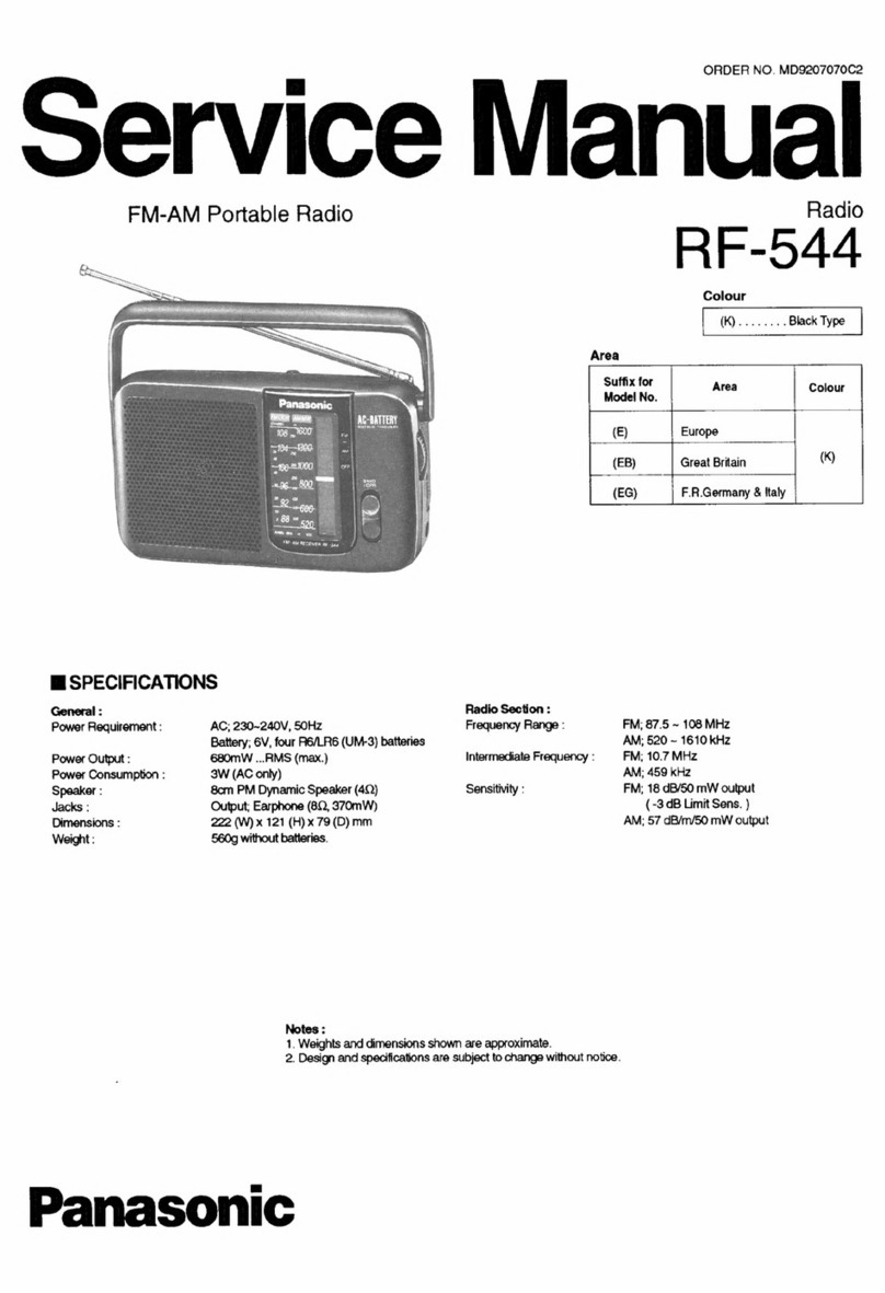
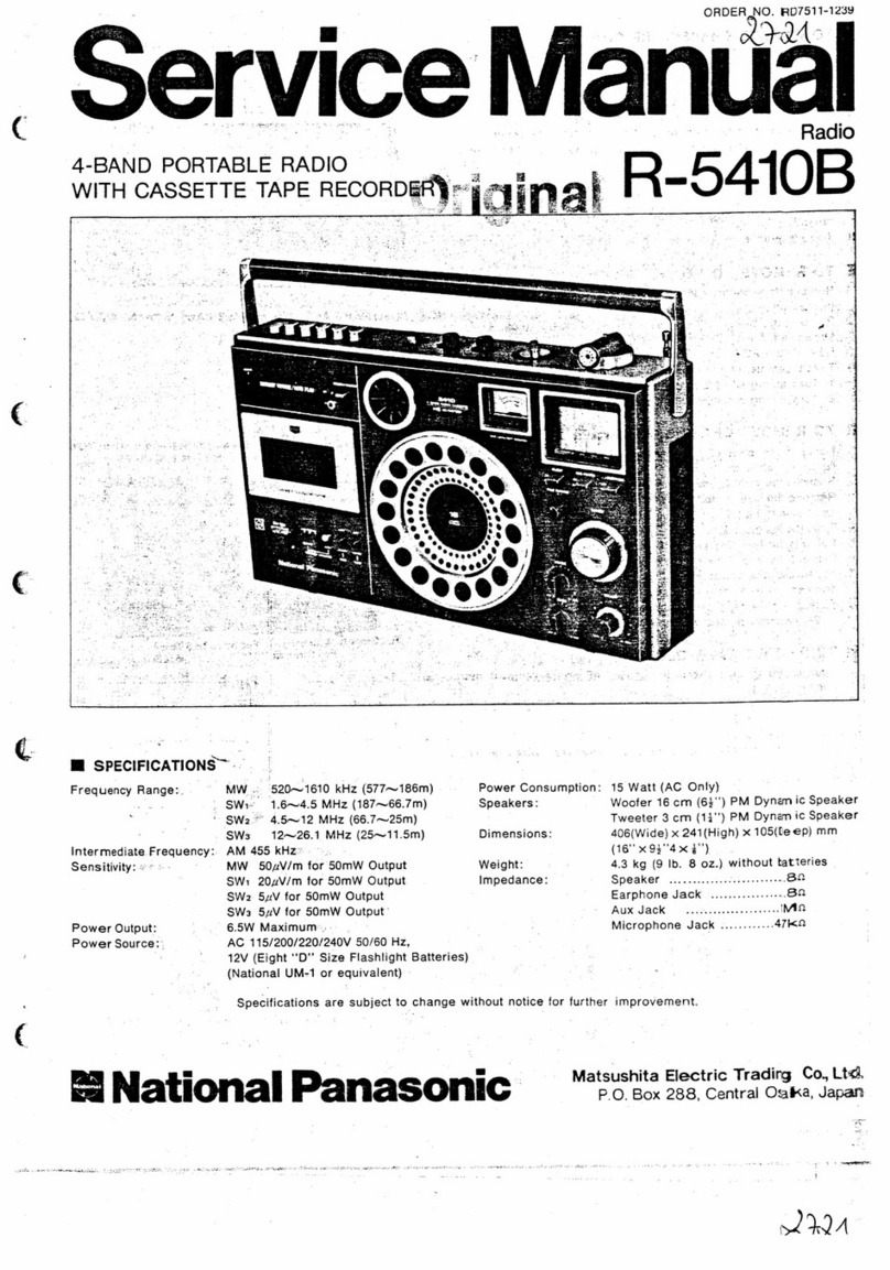
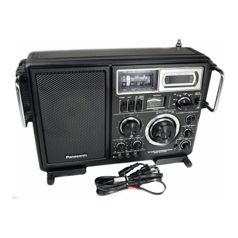
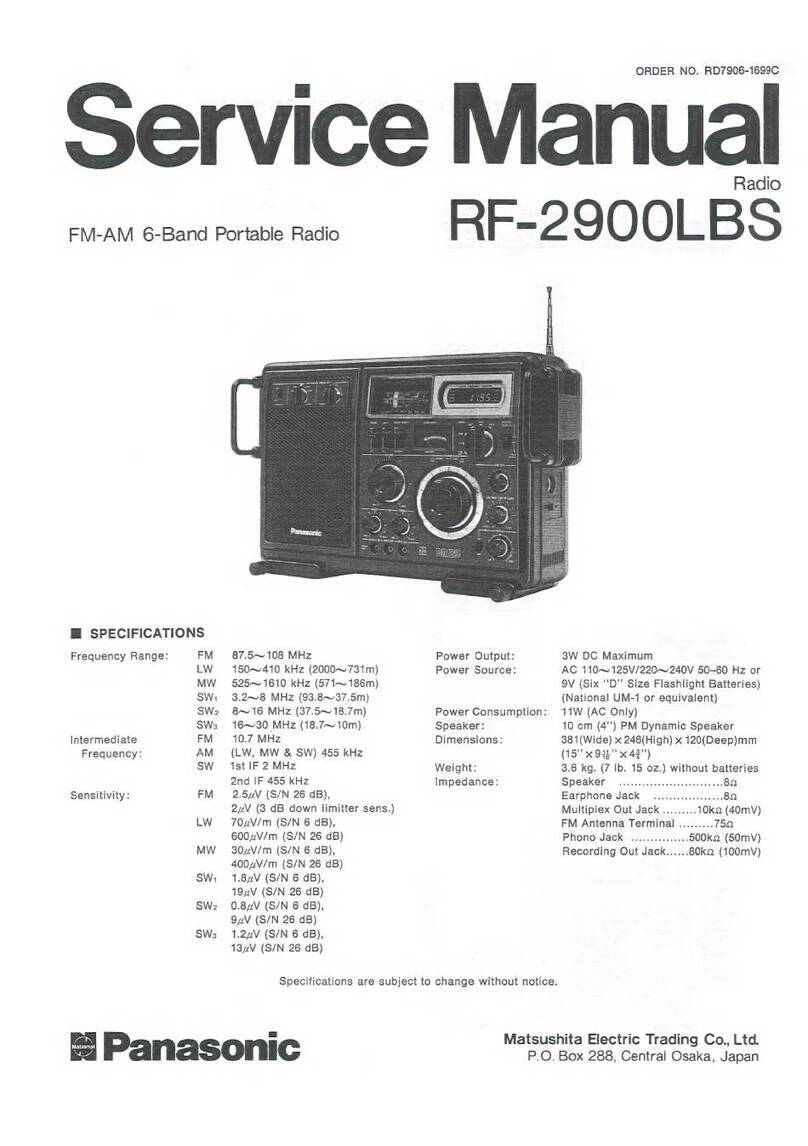
Panasonic RF-3100 User manual

I
ilng
tons
MODELNO RF-31 OO
Read these instructions completely before operating this set

Your new Panasonic radio receiver was manufactured and assem-
bled under exacting quality control standards.
The incorporation of the latesl advances in radio design and the use
of the most modern components ensure outstanding performance
with superb sensitivity, selectivity and tone quality.
Just a few minutes of your time spent reading carefully through
these instructions will assure your obtaining optimum performance
that will bring you continued enjoyment for many years.
WARNING:
TO PREVENT FIRE OR SHOCK HAZARD, DO NOT
EXPOSE THIS PRODUCT TO RAIN OR MOISTURE.
TABLE OF CONTENTS
PRECAUT|ONS...... .............1
HELPFUL HINTS . .. .. . .. . 1
POWERSUPPLY ..,..,,,.2
LocATtoNoFcoNTROLS..... ..........3
CONTROLSANDTHEIRFUNCTIONS ..,,..4
ANTENNAS ......5
RECEIVEROPERATION ..........6
STAND . . .. .. . .. .7
SHOULDERSTRAP ..,...7
SUGGESTIONSFORSAFETY..... ........8
PRODUCTSERVTCE. ..........9
PRECAUTIONS
For your safety and to prevent damage to the set:
I Do not connect the set to any AC outlet other than the type
supplying the specified voltage.
I Avoid cuts, scratches, or poor connections in the AC power cord,
as they may result in possible lire or electric shock hazard. Also,
excessive bending, pulling or slicing of the cord should be
avoided.
I Do not unplug the AC power cord by pulling on the cord. To do so
may cause premature failure or shock hazard. Unplug the set by
pulling on the plug itself.
I Do not operate the set on AC power in a bathroom, as a potential
shock hazard may result. Use battery power when near water.
I When not in use, disconnect the AC power cord from the AC
power outlet. This precaution applies to all electronic equipment.
HELPFUL HINTS
t lf the set is not used lor a long time or is used only from an AC
power source, remove all the batteries to prevent potential
damage due to possible battery leakage.
I When the sound becomes low or distorted, replace all the
batteries with new ones before they are completely discharged.
I Do not subject the set to a temperature higher than 140'F (60'C)'
because characteristics of the internal parts may be adversely
affected by extreme heat. Specifically, never leave the set in a
car exposed to direct sunlight for a long time with all the doors
and windows closed. The cabinet may become deformed, and
deterioration olthe performance may result.
I Do not use benzine, thinner or the like, or any abrasive powder to
clean the cabinet. Wipe it with a soft cloth moistened with a mild
soap and water solution.
The serial number of this product may be found on the label
affixed to the inside of the battery compartment.
You should note the serial number of this unit in the space
provided below and retain this book as a permanent record of
your purchase to aid in identification in the event of thett or
fire.
MODEL NUMBER: RF-3100
SERIAL NUMBER:

POWER SUPPLY
I Battery Operation:
1) Open the Battery Compartment Cover, as shown in the figure.
2) lnserl 8 "D" size (Panasonic UM-1 or equivalent) batteries into
the Battery Compartment, making sure that the batteries are
installed in the specified numerical order, and that the proper
polarities (@ and Q) are maintained.
3) Replace the Battery Compartment Cover.
Note:
Be sure to set the Power Switch to "OFF", when turning the set off.
Unplugging the AC Power Cord from the AC outlet automatically
switches from AC to battery operation, but does not turn the unit of f .
oWhen removing the batteries, start by first lifting up the @ side ol
the "No. 7" battery.
oBattery Condition:
1) Setthe Power Switch to "ON".
2) The Power lndicator will then show the battery condition.
k- Strong --+p- Weak --------r3- Dead ------N
FishtR"E
I AG PowerOperation
1) Open the AC Power Cord Compartment, as shown in the figure.
2) Extend the AC power cord and position the cord in the cabinet
opening provided.
3) Plug the AC Power Cord into an AC power outlet.
The unit will automatically switch from battery to AC operation.
{} power outlel
AC 120 V
@
?
AC
Dull Red
POWER POWER
'.1,2
-o- o
/l\ .-
With weak batteries, the
sound will become dis-
torted, especially at high
volume levels.
Io,t_.-l
POWER
o
-2-

LOCATION OFCONTROLS
-o
.rr.rrtl,,,.
......1 I rttl
aaaaaa l I rata
aaarrr I I rrrr
taaata lJ lalt
tt rt rar ar at tt tlt tt I I tt
aala tt lt tt tt laa l a l a l a l
r t r a rtt tt tt ta rla l I I r I I
MI tt lt ltt a t ttt a r a r ar
I lt r I r I lt aat r at lt a t tt a
tttttrttt t! tttttt lt tt t
-3-

CONTROLS AND THEIR FUNCTIONS
O Telescopic Antenna
Effective on FM and SW, not MW.
For best reception, extend the Telescopic Antenna completely
and position it in the direction which provides the optimum
reception.
@ Digital frequency Display (FREOUENCY DISPLAY)
lndicates the tuned frequency as follows:
FM . . . a decimal figure in MHz (105.9)
MW . . . a three or four digit tigure in kHz (1200)
SW . . . a decimal figure in MHz (15.0)
O BFO On/Off Switch (BFO)
It turns the BFO (Beat Frequency Oscillator) on and off. For SSB
or CW reception on SW, set the switch to "ON". When receiving
neither SSB nor CW, be sure to set the switch to "OFF".
@ Battery Compartment Cover
@ Band Selector (BAND SELECTOR)
It selects the desired band (MW, SW, FM).
@ Power Switch (POWER)
It turns the receiver on and of{.
O Tuning Control (TUNING)
It tunes in the desired station.
@ efO Pitch Control(BFo PTTCH)
Used to obtain clear SSB and CW reception.
Properly turn to SSB or CW signals, set the BFO On/Off Switch
to "ON", and then carefully rotate this control until the signals
are the most suitable.
I RF Gain Control (Mw Sw RF GA|N)
Effective on MW and SW, not FM.
It adiusts the receiver sensitivity for MW or SW (including SSB
and CW) reception. Normally, keep it turned fully clockwise
(MAX). lf the received station is sufficiently strong to cause
overloading or distortion in the receiver, slowly rotate this control
counterclockwise until clear sound is obtained.
@ Treble Control (TREBLE)
It adjusts the high or treble tones.
(D Bass Control (BASS)
It adjusts the low or bass tones.
@ Volume Control (VOLUME)
Used to adjust the volume.
@ Headphone Jack (PHONES)
It is used for the connection of headphones. When the head-
phone plug is inserted, the built-in speaker is automatically
disconnected. The sound through the headphones is heard in
monaural, not stereo.
@ LightSwitch (LIGHT)
When this switch is pressed and the set is turned on, the Signal/
Tuning lndicator is illuminated.
@ Speaker
@ Signal/Tuning Indicator (INDICATOR)
When receiving an MW or SW station, the upper scale operates
as a Signal Strength Meter.
When receiving an FM station, the lower scale operates as a
Tuning Meter.
@ Power lndicator (POWER)
This indicator lights when the set is turned on.
@ Bandwidth Selector (BANDWIDTH)
Effective on MW and SW, not FM.
Normally, set it to "W|DE". Set it to "NARROW" when
experiencing excessive noise, or interference from an adiacent
. station.
@ Recording Output Jack (REC OUT)
When used with the appropriate connection cord, broadcasts
can be recorded onto a tape recorder.
@ Earphone/External Speaker Jack ( F 3 IMP SOONLY)
Used for the connection of an earphone or an 8f) external
speaker.
@ Antenna Selector
Ef fective on MW and SW, not FM. Use the selector to switch from
the built-in to an external antenna on MW, or from a low to a high
impedance antenna on SW.
ln the "LOW lMP" position, the Telescopic Antenna is
disconnected.
@ External Antenna Terminats
Effective on MW, SW and FM. lf the desired station is too weak or
too distant for the receiver to provide satisfactory reception,
connect an appropriate external antenna (and a ground wire) to
these terminals.
@ Stand
@ lC Power Cord Compartment

ANTENNAS
I Antennas:
FM:
oExtend the Telescopic Antenna completely and adjust its length
and angle for optimum reception.
aTo improve reception or receive very distant stalions, connect an
FM antenna (FM dipole anlenna, TV antenna) to the External
Antenna Terminals, as shown in the figure.
MW:
oThe sensitive ferrite core antenna inside the set will provide
excellent MW reception in most areas. For optimum reception, turn
the set in the direction which gives the best results, since the ferrite
core antenna is directional.
SW:
oExtend the Telescopic Antenna completely, keeping it vertical.
oTo improve reception, connect a length of wire, to serve as an
antenna, to the External Antenna Terminals, as shown in the
figure.
Note:
An antenna for the SW bands can be constructed from a length of
wire. A long length of wire will provide better results; however, a
short length of wire is also suitable.
lnner conductor Shield wire
Note:
lf the antenna is connected with 75O coaxial cable instead of 300O
twin lead, the matching transformer is not required.
.How to Connect Antenna Wire to Terminal
.External Antennas
FM
3000 twin lead
75O coaxial cable
Matching transformer
(300o-75o)
l^rt"n
offi + ffi:""(pW"."^
Push and
hold
+
Notesr
oWhen using external antennafor FM and SW reception, shorten the
Telescopic Antenna.
oWhen using the external antennas for SW reception, set the
Antenna Selector to match the particular antenna used.
SW
Antenna Wire lnsulator lnsulator
39 feet (12 m)-=1
T
o-
OE
to Q9
N
Altach here
F
/n1
FJ
I
l=
gL
F
g'%fl',((;
,ry,
Insertwire
-5-

RECEIVER OPERATION
Preparation
Be sure to set the following controls as described below:
oset the RF Gain Control to "0" (clockwise).
(This control has no effect on FM.)
.Rotate the Volume Control clockwise for the desired sound level.
.Set the Antenna Selector to the proper position ("H|GH" or
"LOW"). lnsure that proper connection is made when using an
external antenna.
After confirmation regarding these points, set the Power Switch to
"ON", then proceed with the instructions which follow.
rsw
@ BandSelector ......DesiredSWband
@ Bandwidth Selector . "WIDE"
@TuningConkol .....Desiredstation
@ Bass and Treble Controls . . . . Pleasant level
To reduce interference:
.Set the Bandwidth Selector to "NARROW", then retune.
.Turn the RF Gain Control counterclockwise until the interference
fades away, and then readjust the Volume Control.
.SSB and CW Reception
Set the receiver as shown above ior SW reception, then:
1) BFOSwitch . . .. .. . "ON"
2) BFO Pitch Control
SSB. . . Rotate this control (toward "LSB" or "USB") until the
received signal becomes clear.
Usually for amateur communication, LSB is used under
10 MHz and USB used over 10 MHz.
CW . . . Adjust for the desired tone.
Notes:
.lf the received signal is excessively strong resulting in distorted
sound, rotate the RF Gain Control counterclockwise until a distinct,
undistorted sound is obtained.
.ln receiving two-way communication signals, a possible difference
between the two frequencies may demand further adjustment of
the Tuning Control.
oWhen setting the BFO Pitch Control to "ON" the bandwidth
automatically changes to narrow.
.When receiving at 5.12 MHz, 10.24 MHz, 15.36 MHz and 20.48
MHz, the signal strength meter may shown full deflection to the
right. This is a normal condition and does not indicate that anything
is wrong with this set.
rMw
@ BandSelector ...... "MW"
@ Bandwidth Selector . "WIDE"
@ TuningControl .....Desiredstation
@ Bass and Treble Controls . . . . Pleasant level
Note:
When receiving MW, avoid using the set on or near a steel desk. lf
you use the set on a steel surtace, install rubber feet, as described in
"lnstalling Rubber Feet", on page 7.
To reduce interference:
.Set the Bandwidth Selector to "NARROW", then retune.
aTurn the RF Gain Control counterclockwise until the interference
fades away, then readjust the Volume Control.
.Turn the receiver in the direction which offers minimum
interference.
rFM
@ BandSelector ...... "FM"
@TuningControl .....Desiredstation
@ Bass and Treble Controls . . . . Pleasant level
-6-

STAND
oTilting the front
To tilt the front of the set up, extend the stand and place the set
down on the stand.
I lnstalling Rubber Feet
SHOULDER STRAP
Attach the Shoulder Strap by following the illustration, below:
Note:
While carrying the set with the Shoulder Strap, be careful not to
accidentally knock off the rubber feet (if installed).
Wq.
rubber foot
1 @,inctuded)
(e
I
remove the tape
installation location
To use the set on a steel surface or to prevent it from slipping, install
the 4 rubber feet provided. To intall, first remove the tape from each
foot, to expose the adhesive. Then, secure each foot to the bottom of
the cabinet, as shown in the figure.
N
-7 -

SUGGESTIONS FOR SAFETY
Before using this unit, be sure to read applicable items of the
operating instructions and these salety suggestions carefully; and
afterwards keep them handy for future reference. Take special care
to follow the warnings indicated on the unit itself as well as in the
operating instructions.
1. Avoid places where there is water or humidity.
Do not use this unit near a bathtub, washbasin, swimming pool,
or the like. Damp basements should also be avoided.
2. Don't allow water or any foreign obiect to get inside this
unit.
Don't place small metal objects or anything containing liquid on
or near the unit.
3. Avoid placement of the unit where it will be exposed to the
direct rays of the sun, or where ventilalion is inadequate.
Don't place this unit in a bookcase or between cabinets, or
where curtains or furniture may obstruct the ventilation holes.
4. Place this unit away from heat-emitting appliances.
Never place this unit near a radiator, heat register, stove, or any
other heat-emitting equipment. (lncluding Amplifiers).
5. Placement
Place the unit on a stable, vibration{ree, level shell or stand.
6. Check the voltage rating of this unit belore connecting the
unil to a power supply.
Be sure to connect the unit only to the type ot power supply
indicated in the operating instructions, or as indicated on the
unit itself.
7. Concerning the power outlet(s) of this unit
lf this unit has a built-in electric power receptacle, be sure to
connect only equipment with a power rating not exceeding that
indicated by the receptacle of this unit. (Only connect audio
equipment to this outlet.)
8. Care ol the power cord and plug.
Take care that the cord is not bent sharply (especially near its
connection to the unit or near the plug), that nothing is placed on
it, and that it is not pinched or crushed. Never take hold of the
plug or cord if your hand is wet, and always be sure to grasp the
plug body when connecting or disconnecting it.
9. Ouldoor Antenna grounding.
lf an outside antenna is connected to the receiver, be sure the
antenna system is grounded so as to provide some protection
against voltage surges and built up static charges. Section 810
of the National Electrical Code, ANSI/-NFPA. No. 70-1978,
provides information with respect to proper grounding of the
mast and supporting structure, grounding of the lead-in wire to
an antenna discharge unit, size of grounding conductors,
location of antenna-discharge unit, connection to grounding
electrodes, and requirements for the grounding electrode.
Refer to the figure to the right.
EXAMPLE OFANTENNA
GROUNDING AS PER
NATIONAL ELECTRICAL COOE
INSTRUCTIONS
Ground Clamp
Downlead or
Lead-in Wire
Mast
Ground
Wire
a,b
b
To
Receiver
Antenna
Discharge
Ground
Wire a, b
Ground
Clamps
i; Suitable Grounding Electrode
ii Driven A' lntoThe Earth
(2.44 Meters)
a) Use No. 10 AWG copper or No. 8 AwG aluminum or No. 17 AwG
copper-clad steel or bronze wire, or larger as ground wires for both
mast and antenna discharge ground wire.
b) Secure lead-in wire from anlenna to antenna discharge unit and mast
ground wire to house with stand-off insulators, spaced from 4 teet
(1.22 meters) to 6leet (1.83 meters) apart.
c) Mount antenna discharge unit as closely as possible to where lead-in
enters house.
10. Power lines
When installing an outdoor antenna, install it as far as possible
from power lines.
1 1. ll the unit will not be used lor a long period ol time:
Be sure to disconnect the power cord.
12. Maintenance
Refer to the operating instructions for details.
13. Nevel attempt repairs yoursell:
(a) lf the power cord or plug is damaged.
(b) ll a foreign object or liquid falls into the unit.
(c) lf the unit is exposed to rain.
(d) lf the unit does not function normally, or if operation shows
an unusual change.
(e) lf the unit has been dropped and the cabinet or chassis are
damaged.. . etc.
Unplug the power cord and consult with a qualified technician
(or the dealer from whom the unit was purchased or the nearest
service center).
14. Repairs
Except for adjustments explained in the operating instructions,
do not attempt any repairs yourself. Be sure to request service
from a qualified technician (or your dealer or nearest service
center).
-8-
PRODUCTSERVICE
Should your Panasonic product ever require service, refer to SERIALNUMBER: Locatedonthelabel affixedtotheinsideofthe
enclosed Directory for an Authorized Panasonic Servicenter or battery compartment.
consult your authorized Panasonic dealer for detailed instructions.
-9-
Other manuals for RF-3100
1
Table of contents
Other Panasonic Portable Radio manuals

Panasonic
Panasonic RF-1150LB User manual

Panasonic
Panasonic RF-2800 LBS User manual

Panasonic
Panasonic RF-800UGA User manual

Panasonic
Panasonic RF-888JB User manual

Panasonic
Panasonic RF-2900LBS User manual

Panasonic
Panasonic RF-2900 User manual

Panasonic
Panasonic NATIONAL PANASONIC R-441B User manual

Panasonic
Panasonic R-5410B User manual

Panasonic
Panasonic RF-D10 User manual

Panasonic
Panasonic EY37A2 User manual