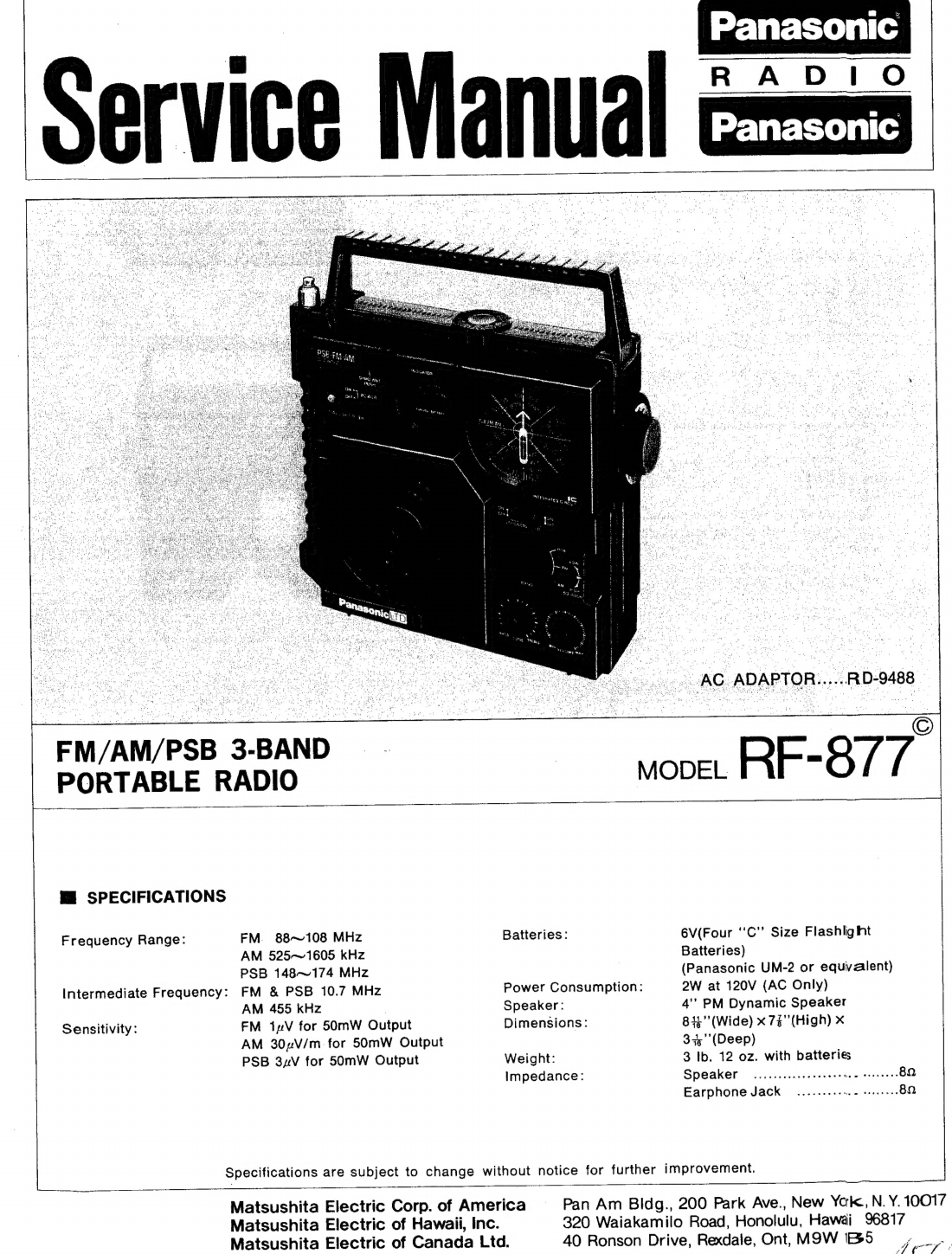
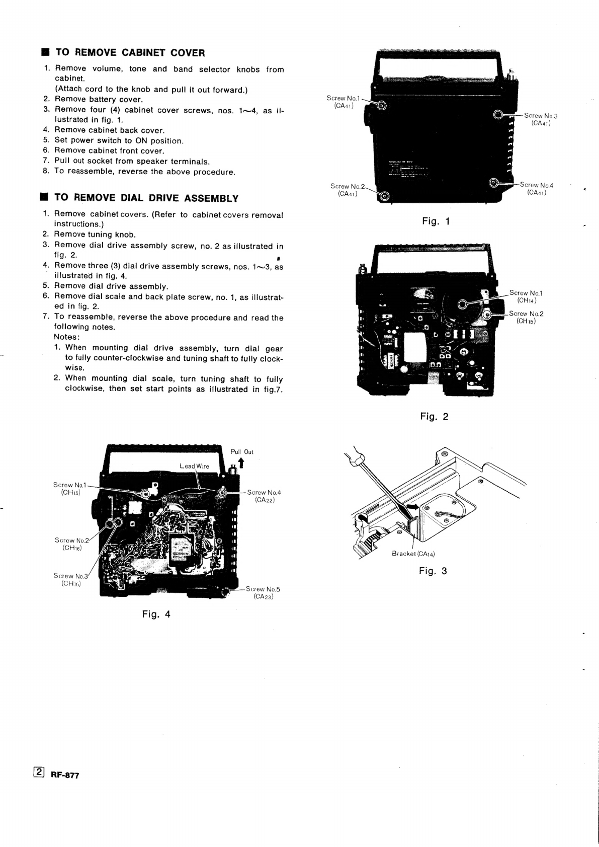
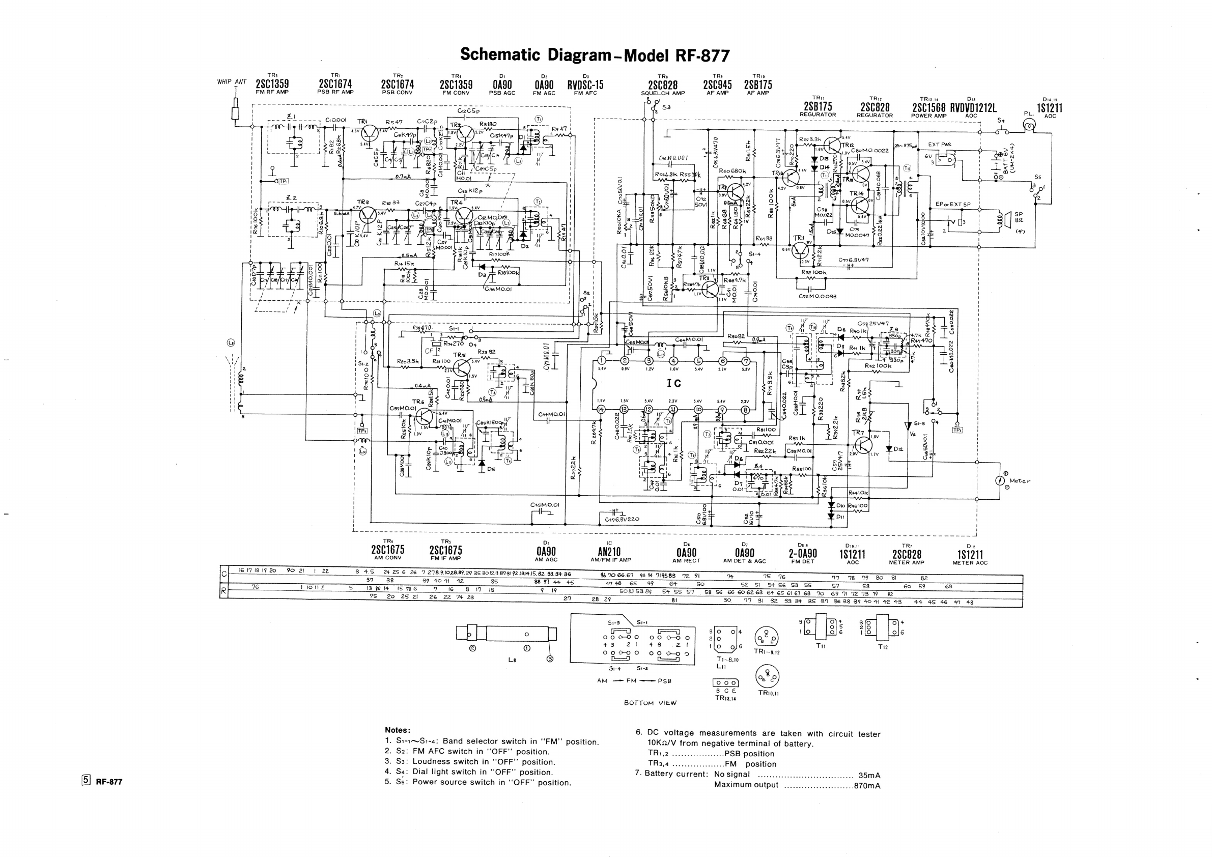
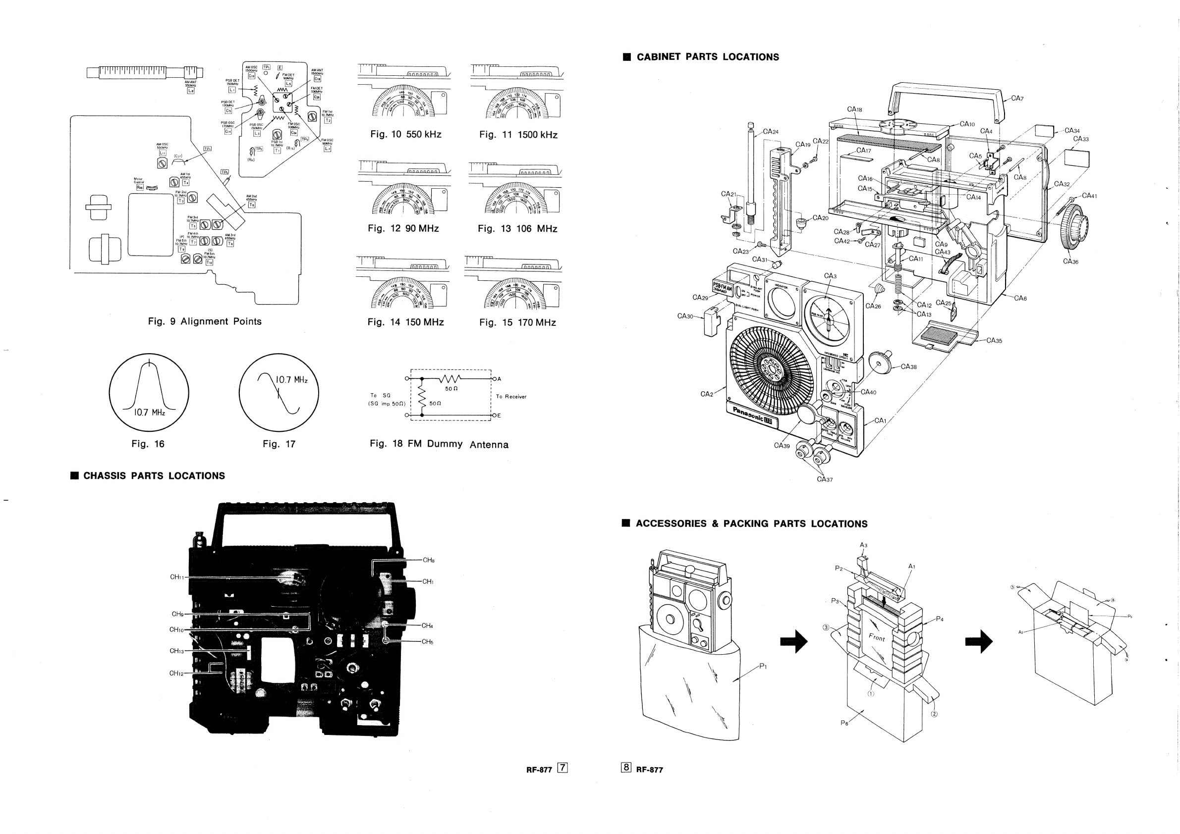
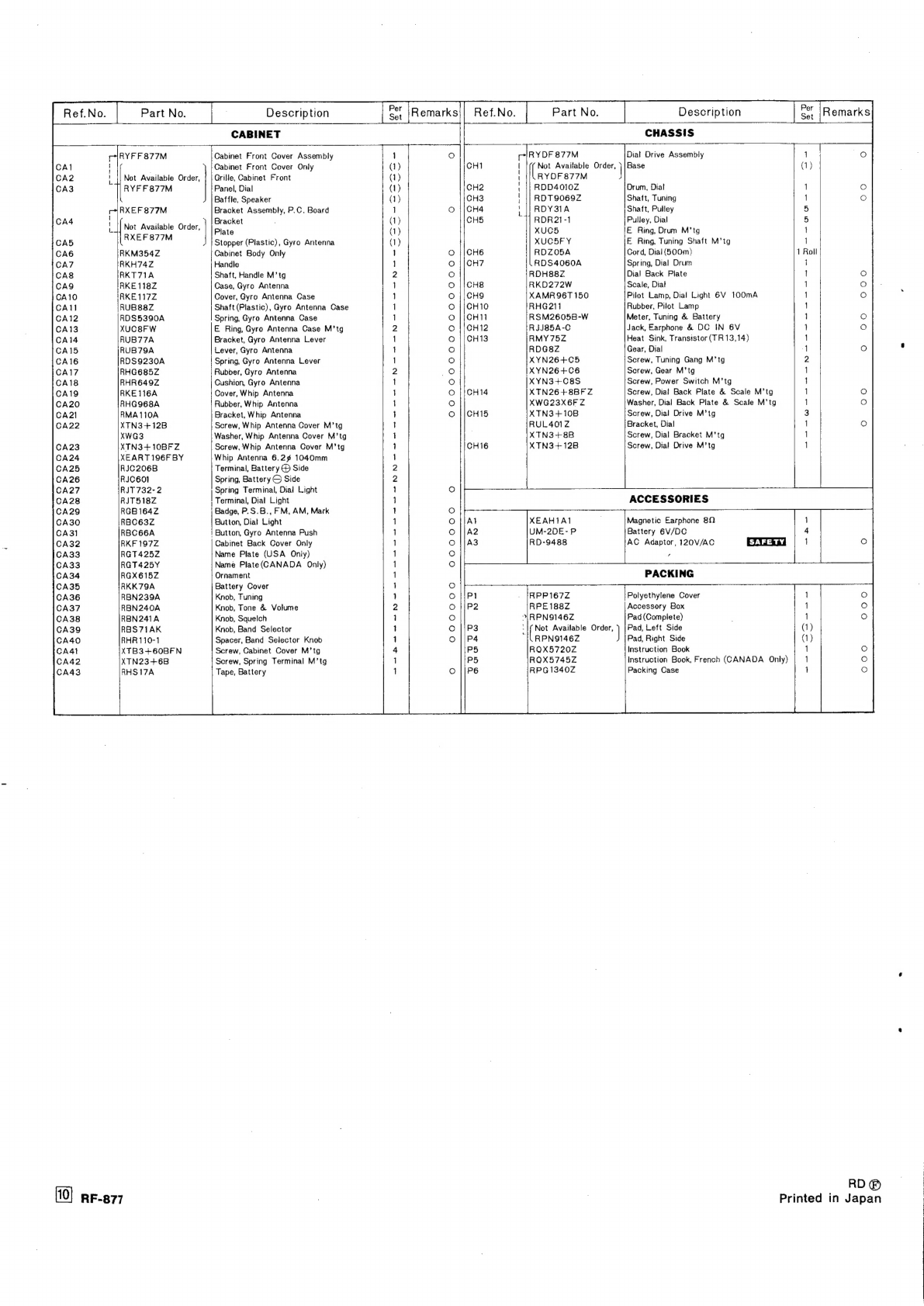
Panasonic RF-877 User manual

Panasonic
Service
Manual
co:
-.
AG
ADAPTOR.....RD-9488_
FM/AM/PSB
3-BAND_~
-
PORTABLE
RADIO
7
MODEL
RF-
Off
ME
SPECIFICATIONS
Frequency
Range:
FM.
88~108
MHz
Batteries:
6V(Four
‘'C’’
Size
Flashlight
AM
525-~1605
kHz
Batteries)
PSB
148-174
MHz
|
(Panasonic
UM-2
or
equivalent)
Intermediate
Frequency:
FM
&
PSB
10.7
MHz
Power
Consumption:
2W
at
120V
(AC
Only)
AM
455
kHz
Speaker:
4’
PM
Dynamic
Speaker
Sensitivity:
FM
inV
for
50mW
Output
Dimensions:
842"
(Wide)
x
7g"'(High)
x
AM
30zV/m
for
50mW
Output
33;'’'(Deep)
PSB
3xV
for
50mW
Output
Weight:
3
Ib.
12
oz.
with
batteries
Impedance:
Speaker
.........cceeeeere
nee
teeteees
82
Earphone
Jack
......
eee
e
eee
BO
Specifications
are
subject
to
change
without
notice
for
further
improvement.
Matsushita
Electric
Corp.
of
America
Pan
Am
Bldg.,
200
Park
Ave.,
New
Yak,
N.Y.
10017
Matsushita
Electric
of
Hawaii,
Inc.
320
Waiakamilo
Road,
Honolulu,
Hawai
96817
Matsushita
Electric
of
Canada
Ltd.
40
Ronson
Drive,
Rexdale,
Ont,
M9W
IBS
ee

M
TO
REMOVE
CABINET
COVER
1.
Remove
volume,
tone
and
band
selector
knobs
from
cabinet.
(Attach
cord
to
the
knob
and
pull
it
out
forward.)
Remove
battery
cover.
.
Remove
four
(4)
cabinet
cover
screws,
nos.
1~4,
as
il-
lustrated
in
fig.
1.
Remove
cabinet
back
cover.
.
Set
power
switch
to
ON
position.
Remove
cabinet
front
cover.
Pull
out
socket
from
speaker
terminals.
.
To
reassemble,
reverse
the
above
procedure.
woN
ee
M™@
TO
REMOVE
DIAL
DRIVE
ASSEMBLY
1.
Remove
cabinet
covers.
(Refer
to
cabinet
covers
removal
instructions.)
Remove
tuning
knob.
.
Remove
dial
drive
assembly
screw,
no.
2
as
illustrated
in
fig.
2.
Py
4.
Remove
three
(3)
dial
drive
assembly
screws,
nos.
1~3,
as
illustrated
in
fig.
4.
.
Remove
dial
drive
assembly.
.
Remove
dial
scale
and
back
plate
screw,
no.
1,
as
illustrat-
ed
in
fig.
2.
7.
To
reassemble,
reverse
the
above
procedure
and
read
the
following
notes.
Notes:
1.
When
mounting
dial
drive
assembly,
turn
dial
gear
to
fully
counter-clockwise
and
tuning
shaft
to
fully
clock-
wise.
2.
When
mounting
dial
scale,
turn
tuning
shaft
to
fully
clockwise,
then
set
start
points
as
illustrated
in
fig.7.
oN
oO
OO
Pull
Qut
lead
Wire
nf
Screw
No.1
(CHi5)
Screw
No.4
(CA22)
Screw
No.3
F,
|
(CHis)
Screw
No5
(CA23)
Fig.
4
RF-877
Screw
No.1
(CA41)
screw
No.3
(CA41}
Screw
No.2
Screw
No.4
;
(CAa1)
(CAa1)
3
Screw
No.1
as
(CH14)
oO
B_
Screw
No.2
(CHi5)
Bracket
(CA14)
Fig.
3

TO
REMOVE
GYRO
ANTENNA
CASE
.
Remove
cabinet
cover.
(Refer
to
cabinet
cover
removal
instructions.)
.
Unsolder
three
(3)
lead
wires
between
core
antenna
and
PC
board
at
PC
board
side.
.
Remove
dial
scale
and
back
plate.
Remove
meter.
.
Remove
bracket
(CA
14)
by
driver
as
illustrated
in
fig.
3.
-
Remove
E
ring
(CA
13)
by
driver
as
illustrated
in
fig.
5.
Remove
gyro
antenna
case.
.
To
reassemble,
reverse
the
above
procedure.
TO
REMOVE
CORE
ANTENNA
.
Push
the
antenna
pop-up
button.
Remove
gyro
antenna
case
cover
by
driver
as
illustrated
in
fig.
6.
.
Unsolder
three
(3)
lead
wires
from
PC
board.
.
To
reassemble,
reverse
the
above
procedure
and
read
the
following
note.
Note:
When
mounting
core
antenna
to
antenna
case,
wiring
three
(3)
lead
wires
as
illustrated
in
fig.
5.
TO
REMOVE
WHIP
ANTENNA
.
Remove
cabinet
back
cover.
(Refer
to
cabinet
cover
removal
instructions)
.
Unsolder
lead
wire
to
whip
antenna
terminal,
as
illustrated
in
fig.
4.
.
Remove
two
(2)
whip
antenna
cover
screws,
nos.
4
&
5,
as
illustrated
in
fig.4.
.
Pull
out
whip
antenna
in
the
direction
of
arrow,
as
illustrat-
ed
in
fig.
4.
.
Remove
whip
antenna
from
whip
antenna
cover.
.
To
reassemble,
reverse
the
above
procedure.
DIAL
CORD
INSTALLATION
GUIDE
.
Remove
dial
drive
assembly
from
chassis.
(Refer
to
dial
drive
assembly
removal
instructions.)
.
Dial
cord
length
is
313”.
.
Turn
dial
drum
to
fully
clockwise.
Arrows
(1~10)
indicate
correct
order
and
direction
of
dial
cord
installation,
as
illustrated
in
fig.
8.
.
Cement
dial
cord
ends.
Pulley
(CHs)
Tuning
Shaft
(CH3)
Spring
(CH7)
Drum
(CH2)
Fig.
8
Cover
(CAio)
Cushion
(CAi8)
+Core
Antenna
\\"
Sa
Sy
Rubber
2
Ay
j
Z
(CA17)
Rubber
(CA17)
Oise
7
Shaft
(CAg)
l
(CA
)
es)
i
Spring
S2
lf,
e
(CAiz)
$e
n
(ula
E
Ring
(CA13)
oD
PA
Spring
oa
(CAi6)
ago
(CA15)
Bracket
:
(CA14)
Fig.
5
RF-877
M@
TUNING/BATTERY
METER
ADJUSTMENT
1.
RADIO
RECEIVER
SETTING
2.
REMARKS
-
Set
band
selector
switch
to
FM.
Adjust
Rae
so
that
the
pointer
of
-
Set
volume
control
to
minimum.
level
meter
stays
as
shown
in
-
Set
power
source
voltage
to
6
volts
DC.
figure
right.
Baie
-
Set
power
switch
to
ON.
—
M@
ALIGNMENT
INSTRUCTIONS
READ
CAREFULLY
BEFORE
ATTEMPTING
ALIGNMENT
Notes:
1.
Set
volume
control
to
maximum.
2.
Set
tone
control
to
treble.
3.
Set
band
selector
switch
to
AM,
FM
or
PSB.
4.
Set
sgueloh
control
to
low.
SIGNAL
GENERATOR
or
SWEEP
GENERATOR
CONNECTIONS
FREQUENCY
5.
Set
loudness
switch
to
OFF.
6.
Set
power
switch
to
ON.
7.
Set
power
source
voltage
to
6
volts
DC.
8.
Set
AFC
switch
to
OFF.
RADIO
DIAL
SETTING
INDICATOR
(VTVM
or
SCOPE)
REMARKS
ADJUSTMENT
F
ashion
loop
of
Point
of
non-
:
455
kHz
Output
meter
Ta
(1st
IFT)
;
:
several
turns
of
wire
interference.
P
=
Adjust
for
maximum
(1)
30%
Mod.
across
earphone
Te
(2nd
IFT
and
radiate
signal
with
400
Hz.
(on/about
jack.
Ts
(3rd
IFT)
output.
into
loop
of
receiver.
600
kHz)
:
Adjust
for
maximum
(2)
y
550
kHz
550
kHz
Li1
(OSC
Coil)
output.
Adjust
Ls
by
moving
coil
bobbin
(Fig.
10)
(*1)Ls8
(ANT
Coil)
along
ferrite
core.
Ci9
(OSC
Trimmer)
Adjust
for
maximum
1500
kHz
(3)
v
1500
kHz
out
put.
Repeat
steps
(Fig.
11)
cre
(AN
amery
|
(2)
and
(3).
(*
1)
Cement
antenna
bobbin
with
wax
after
completing
alignment.
T2
(FM
1st
IFT)
_
|
Connect
vert.
Adjust
for
maximum
rm
a
ee
mee
=
10.7
MHz
ee
amp.
of
scope
to
ue
ey
Ab
tae
amplitude
and
proper
tke
-
point
Tal
are
Re
on
Ae
ecmimnae
to
Tr
(FM
4th
IFT)
400
eee
-)
Z).
chassis.
Ts
(FM
Stn
IFT)
(Refer
to
fig.
16)
(Primary)
Adjust
T10
so
that
10.7
MHz
marker
appears
at
the
center.
(Refer
to
fig
17)
Tio
(FM
5th
IFT)
(Secondary)
High
side
thru.
0.001
uF
to
point
.
Common
to
point
[E]
.
Point
of
non-
interference.
Adjust
for
maximum
Tr
(PSB
1st
IFT)
|
oe
itude
A
Ae
Connect
to
point
through
FM
Dummy
antenna.
Common
to
point
[E]
.
(Refer
to
fig.
18).
L7
(FM
OSC
Coil)
Ls
(FM
DET
Coil)
Output
meter
across
voice
coil.
(
*
2)Adjust
for
maxi-
mum
ouput.
(7)
LFig.
12)
C34
(FM
OSC
Trimmer)
Coe
(FM
DET
Trimmer)
(*
2)Adjust
for
maximum
output.
Repeat
steps
(7)
and
(8).
106
MHz
[Fig.
13]
PSB-RF
ALIGNMENT
(8)
-
106
MHz
Connect
to
point
jeans
through
FM
Dummy
Output
meter
:
.
(9)}
antenna.
Common
to
150
MHz
Poo
MHZ
BetoGs
7
OSC
Coil)
|
(*2)
Adjust
or
maxi-
chassis.
(Refer
to
(Fig.
14)
voice
coil.
Li
(PSB
mum
ot
put.
fig.
18)
DET
Coil)
Cia
(PSB
OSC
(
*
2)
Adjust
fp
r
maxi-
170
MHz
Trimmer)
mum
oitput
170
MHz
It
put.
(10)
(Fig.
15)
‘“
Cs
(PSB
DET
Repeats
teps
Trimmer)
(9)
and
(10).
Three
output
responses
will
be
present:
Proper
tuning
is
the
center
frequency.
(
*
2)
RF-877

RF-877
Schematic
Diagram-Model
RF-877
Di4.t5
181211
TR3
TRi
=
TR,
Dy
D2
D3
TRs
TR»
TRio
wip
ANT
9gc1359
—»s«ASC1B74.
~=—«s«2SC1874
«2801359
O90
~—«sOABO~—-RYDSC-15
9sc828
«280945
2SBI75
FMRF
AMP
PSB
RF
AMP
PSB
CONV
FM
CONV
PSB
AGC
FM
AGC
FM
AFC
SQUELCH
AMP
AF
AMP
AF
AMP
eae
ae
ak,
=
!
I
i
os
nha
ah
Ph
al Sa
i
a
ee
ed
$53
29B1/9
280828
2801968
RVDVD1212L
:
Ci2CSp
7
2
REGURATOR
REGURATOR
POWER
AMP
AOC
:
me
C10.00!
TRI
Rs47
C»C2p
TR
PaiBO.:
Weta
utes
1c
Nee
We
ee
ee
rey
Sere
Syd
|
POS
se
Fe
gee
ene
E
=
oe
(oy
QO
SO
O
O
y
aeY
ay
Gskt+7p
S
Ley
Ges
oe
Cisk47p
2
ae
:
54V
7
y
°
=
2.2V,
3
tN
COMO,
0022
lps
*
4
Ca
V1
0.00)
~
;
Ee
2
oT
©)
a
on
<5,
=
_
Rs4b.8k
RSS
10k
Sbepaiie
%X)
SS
:
|
p
3
|
(2
ip
Re
oe
he
oO
ris
<
3
le
SP
O
ae
la
Ce
Mo,
s
=
|
311
be
=
3
19
aru,
8s21§
(4)
a
ie
Casio
a
|
:
iret
©
|
|
|
O
ba
:
8
8
:
R92
100k
!
0
ral
3
;
18
!
j
C76M
0.0033
!
tac
:
!
N
|
N
'
ls
oe
sas
ei
es
Sees
if
2
j
7
|
“Q
'
|
S$
|
=
l
;
3]
|
f
OQ
1
a=
a:
3
ne
4
|
©
ih
|
i
F
!
,
At
O)
®
Deter
O
Q
|
=H
Q
:
oS
!
C4976.3V220
O
e
;
a
haha
lw
ia,
Soc
nal
Se
ge
Pd
rate-setting
ne
hak
a
4
TRe
TR
Ds
Ic
De
D7
De.s
Dio
TR?
Di2
2801679
2801675
0A90
AN210
0A90
0A90
2-0A90
181211
280828
181211
AM
CONV
FM
IF
AMP
AM
AGC
AM/FM
IF
AMP
AM
RECT
AM
DET
&
AGC
FM
DET
AOC
METER
AMP
METER
AOC
9O
2
IG
17
18
19
20
L722
3.45
24
256
26
7
278.9.1028.89.29
35
3012.1.87.31
92
13:14.1S,
82.33
34
36
%$67066.67
93
94
719583
72
91
14
1S
16
77
~°78
99
+B
B2
87-388
39
404,
42
8S
889144
45
4748
6S
49
6+
SO
S2
Si
5¢
56
58
5S
59 58
60.
59
63
AG
I
totle2
S
13
90
14
1S
76
7
6
#28
17
18
Gg
19
$08353
84
S¢+
5S
S7
58
56
66
606263
64+
65
6167
68
TO
69
1
72
13
1%
GP
75.
20
25
21
26
22
7%
23
21
28
29
Bi
30
17
31
32
83 34
85
89
36
38
39
4041
42
483
44
45
46
47
48
:
:
0°
o
BoE
110
oJ6
TRing11
Ti
Ti2
T1~8,10
Si-4
Si-2
Li
Q
AM
—=-FM
——=PpsB
Ce
&
BCE
TRi0,11
TR13,14
BOTTOM
VIEW
Notes:
6.
DC
voltage
measurements
are
taken
with
circuit
tester
1.
Si-1~S1-4:
Band
selector
switch
in
‘‘FM”’
position.
10KQ/V
from
negative
terminal
of
battery.
2.
S2:
FM
AFC
switch
in
‘‘OFF’’
position.
Es
3
ee
ae
ee
PSB
position
3.
S3:
Loudness
switch
in
‘‘OFF’’
position.
WSs
ie
haa
eca
diets
FM
position
4.
Sa:
Dial
light
switch
in
‘‘OFF’’
position.
7.
Battery
current:
Nosignal
...........ccccccccceceeceecce
eee
35mMA
5.
Ss:
Power
source
switch
in
‘‘OFF’’
position.
Maximum
output
........................
870MA
AOC

OO
QO
COOOOO
®
©)
2@@
SO@&
Lé
Lrisht
L3
2
4
De
Dt
D8
De
IC
Té
Ta
Is
LoT7
Tio
13
Circuit
Board
Wiring
View-Model
RF-877
TRs
TRe
Ds
TT?
Li
Ta
Li2
on
Diz
D3Dw4
TRiz
Djs
14
TRaTRia
TRB
TRe
TRio
Tun
=
T12
25:
-875mA
Ss
Lg
AM
ANTENNA
COIL
POWER
SWITCH
Sa
PL
die
le
DIAL
LIGHT
SWITCH
4”
PM
DYNAMIC
SPEAKER
METER
s+
@
-
@
BATTERY
(8)
(6V)
65)
Rs6
10K
(B)
iL1|:
|=)
G)
EAR
PHONO
SQUELCH
CONTROL
3]
:
{
@
EXT
POWER
s)
SOURCE
JACK
WHIP
ANTENNA
(10)
(Dp
@
R50
10K
(A)
Rs3
50K
(D)
I)
TONE
CONTROL
VOLUME
CONTROL
31)
(30)
S
(24)
nF-877
[6]
|

M@
CABINET
PARTS
LOCATIONS
amosc
[TP]
[E}
O
1500kHz
FM
DET
90MHz
a
a
PSB
DET
AMANT
550kHz
1SOMHz
PSB
DET
170MHz
[cs]
PSB
OSC
170MHz
[oul
AM
OSC
550kHz
[Ls)
(C37)
iQ)
—
|TP2)
u
re
—c—
Mcter
@
7
9
t
/
Control
[74]
bs
|
Lf
[rs]
PEs
CAi5
ase
Soy
ag
ae
oe
SSH
fa
-CAa1
3
|
ree
ATE
ay
=
ft
M
2n
10.7MHz
AM
2nd
T
455kHz
QS
[Te]
i;
2
Oe
FM
41h
AM
3rd
(P)
10.7MH2z
455kH
‘mast
(12)
(OD)
|)
Try
tl
al
IO
Cd
wD,
((
te
(an
SA
CAI2
CA25
4
.
,;
;
Y-*CA13
)
Fig.
9
Alignment
Points
ee
“ys
S
r
oS
fats
Bes
tes
os
Rs
ee
SE
ene
4
er)
CA38
ra
Se
————)
A
IS
NS)
SS
SS
‘4:
!
9S
NN
|
SOT
mM
TSS
|
/
To
SG
To
Receiver
CA2
Si,
HWE
(SG
imp.
50M)
RT
NW
|
SEE
Fig.
16
Fig.
17
Fig.
18
FM
Dummy
Antenna
Mi
CHASSIS
PARTS
LOCATIONS
RF-877
RF-877

mM
REPLACEMENT
PARTS
LIST
NOTES:
1.
Part
numbers
are
indicated
on
most
mechanical
parts.
Please
use
this
part
number
for
parts
orders.
2.
EXGGGREY
Indicates
that
onty
parts
specified
by
the
manufacturer
be
used
for
replacement
in
critical
circuit.
Part
No.
Description
Per
Remarks
INTEGRATED
CIRCUIT,
TRANSISTORS
AND
DIODES
IC
TH
ls2
TR3,4
TR5,6
TR7,8,12
TRO
TR10,11
TR13,14
D1,2,5,6,7
D3
D8&,9
1D
410,11,12,14,
15
D1i3
CF
Ly
L2,6
IL3
L5
L7
L8
L9,12,13
yuu
L14
T1,2
T3,5,7
T4
T6
T8
T9
T10
T1I
T12
R53
R50
R46
R56
AN2i0
2801674
25C1359
25C
1675
256828
250945
2S5B175
2S5C
1568
O0A90
RVDSC-15
2-O0A90
191211
RVDVDi212L.
EYV320D1R2J52
RVF107MFB
RLD4Y43
RLQY30S1-0
RLO4Y44
RLDO4Y44
RLO4Y43
RLF
2X5-0
RLQY
7585
RLO2M1
RLQY25S5-0
RLiI4M101
RLI4M301
RLI2M203
RLI2M205
RLI2M402
RL14M501
RLI4M502
RLT3F30-V
RLT2H25-V
RVV54D38-A
RVV14A39-A
EVLT4AA00B23
EVH89AF
35B
14
C4,13,17,20,
25,33
C5,14
AM/FM
IF
Amplifier
P.S.B.RF
Amplifier,
P.S.B.
Converter
FM
RF
Amplifter,
FM
Converter
FM
1F
Amplifier.
AM
Converter
Meter
Amplifier,
Squelch
Amplifier,
Regulator
AF
Amplifier
AF
Amplifier,
Regulator
Power
Amplifier
P.S.B.
AGC,FM
AGC,
AM
AGC,
AM
Rectifier,
AM
Detector
&
AGC
FM
AFC.
FM
Detector
Operation
Compensator,
Meter
Operation
WOMNN
-
Fnynn-
1
1
pair
5
Compensator,
Power
Operation
Compensator
Power
Operation
Compensator
VARIATITE
|
Variatite
CERAMIC
FILTER,
COILS
AND
TRANSFORMERS
Ceramic
Filter
P.S.B.
Detector
Coil
Choke
Coil
P.S.B.
Oscillator
Coil
FM
Detector
Coil
FM
Oscillator
Coil
AM
Antenna
Coil
Choke
Coil
AM
Oscillator
Coil
Choke
Coil
P.S.B./FM
1st
JF
Transformer
FM-P.S.8.
2nd,3rd,4th
iF
Transformer
1st
AM
IF
Transformer
2nd
AM
IF
Transformer
3rd
AM
1F
Transformer
FM-P.S.B.5th
IF
Transformer
,
Primary
FM-P.S.8.
5th
IF
Transformer
,
Secondary
Input
Transformer,
P=
7002:S=1KQ
Output
Transformer,
P
=250:S
=8N
VARIABLE
RESISTORS
—_
50K
(D},
Volume
Control
10K
(A),
Tone
Control
2KN
(B),
Meter
Control
10K
2
(B),
Squelch
Control
VARIABLE
CAPACITORS
RCV2X-4216TM
ECV1ZWI10X32
Tuning
Gang,
W/Trimmer
(C
18,19,
26,34)
Trimmer
21
Le
Z3
Z4
RXABPF
17402)
RXABPF
10801H
EXASDLO4C
EXAF203Z2471R
COMPONENT
COMBINATIONS
Coils
&
Capacitors
Coils
&
Capacitors
330PF
x3,
4.7KQK2
0.01
nF
x2,
4700
1
1
SPEAKER
SP
EAS10P31SG
RSRIOOZK-A
RST36A-P
RST33Z5-F
R26
R63
R2
R30
R37
R47
R67,80
R1,23
R8,64
R5,9,19
R11,31,35,45
R38,
70
R22
R40,
41, 62,
81
R61,79
R39,
71
R20,
69,
77
R28,33,66
R2,10,54
R25,
29,
36,44
55
R27,32,65
R57,58
R34
R13,17,18,
68,
72,76
R48
R73
R60
R78
R6
R43
R75
R7,16
R84
R82
R74
R83
R14
R15
R42
C30
C88
C10
C1,51
C22,42,49,74
96
C48,54,59
C8,9,
21,
28,
29,83,92,94
ERD18SJ152
ERD18SJ680
ERD18SJ101
ERDi8SJ820
ERD18SJ102
ERD18SJ47%
ERD18V
5330
ERD18VJ820
ERDI8VJ181
ERDi8VJ470
ERD18VJ101
ERD18VJ221
ERD18VJ68)
ERDi8VJ102
ERD18VJ152
ERD1I8VJ222
ERD18VJ332
ERD18V
J472
ERDI8V
J682
ERD18VJ103
ERD18VJ223
ERD18V
5473
ERDt8V
J683
ERDABNSIOS
ERD18VJ474
ERD18VJ271
ERD
18V
J684
EROD18VJ471
ERD18T
J821
ERD18T
J823
ERD18T
J101
EROD187TJ102
ERO18TJ124
ERX12ANJR22U
ERDI8TJ271
ERD18TJ152
ERO18VJ153
ERD18TJi22
ERD18TJ104
ECGCO1HO20C
ECCD1HO30C
ECCD1HO040CG
ECCDIHO50CC
ECCD1HO700C
EGCDIH1IZ0KC
ECCD1H470KC
ECCD1IHS560K
ECCDIH181K
ECCD1IH270KC
ECKD1H102PF
ECKE1H103PF
ECKE1H223PF
ECKEtH1IO2MD
RE
Si
1.5KQ,
680,
1000,
820,
STORS
watt,
+5°%,
Carbon
LeWatt,
+5%,
Carbon
Watt,
+5%,
Carbon
Watt,
+5%,
Carbon
Per
4”
PM
Dynamic
Speaker,
imp.
80
SWITCHES
Band
Selector
Switch
AFC
&
Loudness
Switch
Power
Switch
O00
C80
ECKEtH222MD
C76
EGKE1H332MD
C79
ECKE1H472MD
C11,31,36,37,
|ECKE1TH1O3MD
38,
41,44,
45,
53,55,64,65
91,93,97
C60,
78
C8l
C40
C85
C82
C47
C50
C75,77
C52
C57,58
ECKE1TH223MD
ECQGO05683MZ
ECOSi3015Z
ECQS1152K2Z
ECEA10V
1000
ECEA6V220
ECEA6V100
ECEA6V47
ECEAI6V10
ECEA25V4R7
ECEA5OVI
ECEASOZRI
ECEA6V470
ECCD1HO50CC
C66,67,72
C63,
70,71
C95
ECCD1HO70DC
ECCD1HO30CC
TKQ,
‘Watt,
+5%,
Carbon
4700,
Watt,
£5%,
Carbon
33,
‘Watt,
£5%,
Carbon
820,
LeWatt,
+£5%,
Carbon
1802,
J*eWatt,
+5%,
Carbon
47Q,
JgWatt,
£5%,
Carbon
1000,
eWatt,
+5%,
Carbon
2200,
eWatt,
45%.
Carbon
6800,
}eWatt,
+5°%,
Carbon
TKQ,
AgWatt,
£5°%,
Carbon
1.5KQ,
JsWatt,
+5%,
Carbon
2.2KQ,
JeWatt,
+5%,
Carbon
3.3KQ,
Watt,
+5%,
Carbon
4.7KQ,
Watt,
+5%,
Carbon
6.8KQ,
Watt,
+5%,
Carbon
TOKO,
weWatt,
+5%,
Carbon
22K,
JeWatt,
+52%,
Cardon
47K,
KwWatt,
+5%,
Carbon
68kKO,
wWatt,
+5%,
Carbon
100KQ,
Watt,
+5%,
Carbon
470KQ,
“Watt,
&+5%,
Carbon
2700,
MWatt,
£5%,
Carbon
680K,
Watt,
+5%,
Carbon
470n,
Watt,
+5%,
Carbon
8200,
Watt,
+5%,
Carbon
82KQ,
MWatt,
+5%,
Carbon
1000,
Watt,
+5%,
Carbon
1KQ,
MWatt,
+5%,
Carbon
120KQ,
MWatt,
+5%,
Carbon
0.220,
Watt,
+5%,
Metal
Oxied
2702,
Watt,
+5%,
Carbon
1.5KQ,
MWatt,
+5%,
Carbon
1I5KQ,
MWatt,
+5%,
Carbon
1.2K,
‘Watt,
+5%,
Carbon
iOOKQ,
Watt,
+5%,
Carbon
CAPACITORS
2PF,
BOWV,
+
0.25PF,
Ceramic
3PF,
5OWV,
+0.
25PF,
Ceramic
4PF,
5OWV,
+0.
25PF,
Ceramic
5PF,
BOWV,
+0.
25PF,
Ceramic
7PF,
5OWV,
+0.5PF,
Ceramic
10PF,
5SOWV,+10%,
Ceramic
12PF,
5OWV,+10%,
Ceramic
47PF,
5OWV,
+£10%,
Ceramic
(USA
Only)
56PF,
5OWV,
10%,
Ceramic
180PF,
5OWV,
+10%,
Ceramic
27PF,
5OWV,
410%,
Ceramic
0.001nF,
SOWV,+'90%,,
Ceramic
0.01
4
F,
SOW,
+1092,
Ceramic
0.022uF,
S0WV,
+'09*,,
Ceramic
0.001
uF,
5OWV,:+20%,
Ceramic
0.0022
uF,50WV,+20°%,
Ceramic
0.0033
nF,
50WV,+20%,
Ceramic
0.00474F,50WV,+20%,
Ceramic
10.0inF,
5SOWV,+20%,
Ceramic
0.022uF,
S5OWV,+20%,
Ceramic
0.068uF,
SOWV,+20%,
Polyester
300PF,
i25WV,+5%,
Styrol
}1500PF,
125WV,+10%,
—
Styrol
1OO0OuF,
10WY,
Electrolytic
220uF,
6.3WV,
Electrolytic
100uF,
6.3WV,
Electrolytic
47
pF,
6.
3WYV:
Electrolytic
10uF,
16WY,
Electrolytic
4.7
pF,
25WV,
Etectroiytic
1
uF,
50WwV,
Etectrolytic
0.1
uF,
5OWVY,
Electrolytic
470nF,
6.3WYV,
Electrolytic
5PF,
50OWYV,
+0.
25PF,
Ceramic
{USA
Only)
7PF,
5OWV,
+0.5PF,
Ceramic
(CANADA
Only)
3PF,
50WV,
+0.
25PF,
Ceramic
(CANADA
Only)
Set
|
Remarks
NN
BHO
woe
owanre~~
RF-877
[9]

CAI
CA2
CA3
CA4
CA5
CA6
CA7
CA8
CAY
CA10
CAI1
CA12
CA13
CA14
CA15
CA16
CA17
CA18
CA19
CAZ0O
CA21
CA22
CA23
CA24
CA25
CA26
CA27
CA28
CA29
CA30
CA31
CA32
CA33
CA33
CA34
CA35
CA36
CA37
CA38
CA39
CA40
CA4t
CA42
CA43
cond
RYFF
877M
Not
Available
Order,
RYFF
877M
r|IRXEF
877M
i_||
Not
Available
Order,
eee
RKM354Z
RKH74Z
RKT71A
IRKE
118Z
IRKE117Z
RUB88Z
RDS5390A
XUCBFW
RUB77A
RUB79A
RDS9230A
RHG685Z
RHR649Z
RKE
116A
RHGO68A
RMA110A
XTN3+12B
XWG3
XTN3+10BFZ
XEART196F
BY
RJC206B
RJC6O1
RJT
732-2
RJT518Z
RGB164Z
RBC63Z
RBC66A
RKF
197Z
RGT4252Z
RGT425Y
RGX615Z
RKK79A
RBN239A
RBN240A
RBN241A
RBS71AK
RHR110-1
XTB3+60BFN
XTN23+6B
RHS17A
RF-877
CABINET
Cabinet
Front
Cover
Assembly
Cabinet
Front
Cover
Only
Grille,
Cabinet
Front
Panel,
Dial
Batfie,
Speaker
Bracket
Assembly,
P.C.
Board
Bracket
Plate
Stopper
(Plastic),
Gyro
Antenna
Cabinet
Body
Only
Handle
Shaft,
Handle
M’tg
Case,
Gyro
Antenna
Cover,
Gyro
Antenna
Case
Shaft
(Plastic),
Gyro
Antenna
Case
Spring,
Gyro
Antenna
Case
E
Ring,
Gyro
Antenna
Case
M’tg
Bracket,
Gyro
Antenna
Lever
Lever,
Gyro
Antenna
Spring,
Gyro
Antenna
Lever
Rubber,
Gyro
Antenna
Cushion,
Gyro
Antenna
Cover,
Whip
Antenna
Rubber,
Whip
Antenna
Bracket,
Whip
Antenna
Screw,
Whip
Antenna
Cover
M’tg
|
Washer,
Whip
Antenna
Cover
M’tg
Screw,
Whip
Antenna
Cover
M’tg
Whip
Antenna
6.29
1040mm
Terminal,
Battery
€D
Side
Spring,
Battery
©
Side
|
Spring
Terminal,
Dial
Light
;
Perminal,
Dial
Light
|
Badge,
P.S.B.,
FM,
AM,
Mark
Button,
Diat
Light
|
Button,
Gyro
Antenna
Push
Cabinet
Back
Cover
Only
Name
Plate
(USA
Only)
Name
Plate(CANADA
Only)
Ornament
Battery
Cover
Knob,
Tuning
Knob,
Tone
&
Volume
Knob,
Squelch
Knob,
Band
Selector
Spacer,
Band
Selector
Knob
Screw,
Cabinet
Cover
M’tg
Serew,
Spring
Terminal
M’tg
Tape,
Battery
(1)
(1)
(1)
(1)
(1)
(1)
~—o_
—
=
fb
=
ew
eS
Ap
eB eB SB Sm
SS
i
a
Et
ONO
RK
HK BR
PSP
RK
BKB
KN
KH
BP
KenNnNeRK
Kr
RKP
Knee
eo
—
oo0oo0o0o0o0qo0o0Cc0qo0
0g 0g
0
00
oO
OoO0o00000
OoOCco000
O
CH1
CH2
CH3
CH4
CHS
CH6
CH?
CHB
CH9
CH10
CH11
CH12
CH13
CH14
CH15
CH16
poor
occe
ce
Part
No.
RYDF
877M
a
Available
Order,
RYOF
877M
RDD4010Z
RDT
90692
RDY3IA
RDR2t-1
XUC5
XUCBFY
RDZOSA
RDS4060A
RDH88Z
RKD272W
XAMR
96T
150
RHG211
RSM2605B-W
RJJ85A-C
RMY
752
RDG8Z
XYN26+C5
IXYN26+C6
XYN3+C8S
XTN26+8BFZ
XWG23X6F
Z
XTN3+10B
RUL4012
XTN3+8B
XTN3+128
RPP167Z
RPE188Z
IRPN9146Z
7
Ge
Available
Order,
RPN91462
RQX57202
RQX5745Z
RPG1340Z
|
Description
CHASSIS
Per
Remarks
Diat
Drive
Assembly
1
Oo
Base
(1)
Drum,
Dial
Shaft,
Tuning
Shaft,
Pulley
Pulley,
Dial
E
Ring,
Drum
M’tg
E
Ring,
Tuning
Shaft
M'tg
Cord,
Dial
(500m)
1
Spring,
Dial
Drum
Dial
Back
Plate
Scale,
Dial
Pilot
Lamp,
Dial
Light
6V
100mA
Rubber,
Pilot
Lamp
Meter,
Tuning
&
Battery
Jack,
Earphone
&
DC
IN
6V
Heat
Sink,
Transistor
(TR13,14)
Gear,
Dial
Screw,
Tuning
Gang
M’tg
Screw,
Gear
M’tg
Screw,
Power
Switch
M’tg
Screw,
Dial
Back
Plate
&
Scale
M’tg
Washer,
Dial]
Back
Plate
&
Scale
M'tg
Screw,
Dial
Drive
M’tg
Bracket,
Dial
Screw,
Dial
Bracket
M’tg
Screw,
Diai
Drive
M’'itg
O00
ACCESSORIES
Magnetic
Earphone
80
Battery
6V/DC
AC
Adaptor,
120V/AC
¢
PACKING
Polyethylene
Cover
Accessory
Box
Pad
(Complete)
Pad,
Left
Side
Pad,
Right
Side
Instruction
Book
instruction
Book,
French
(CANADA
Only)
Packing
Case
OO90
o_o
~~
=
et
see
~~ Ne
O00
RD
®
Printed
in
Japan
Table of contents
Other Panasonic Portable Radio manuals

Panasonic
Panasonic R-5410B User manual

Panasonic
Panasonic RF-888JB User manual

Panasonic
Panasonic RF-1150LB User manual

Panasonic
Panasonic RF-2200 User manual

Panasonic
Panasonic RF-800UGA User manual

Panasonic
Panasonic RF-544 User manual

Panasonic
Panasonic RF-2900 User manual

Panasonic
Panasonic RF-2900LBS User manual

Panasonic
Panasonic EY37A2 User manual

Panasonic
Panasonic EY37A2 User manual