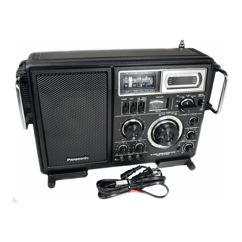
Panasonic RF-800UGA User manual

© Panasonic Corporation 2012. All rights reserved.
Unauthorized copying and distribution is a violation of
law.
PSG1210003CE
FM-MW-SW1-SW2 Portable Radio
Model No. RF-800UGA
RF-800UGS
Product Color : (K)...Black Type
TABLE OF CONTENTS PAGE PAGE
1 Safety Precautions----------------------------------------------- 3
1.1. General Guidelines---------------------------------------- 3
1.2. Protection Circuitry---------------------------------------- 3
1.3. Safety Part Information----------------------------------- 3
2 Warning-------------------------------------------------------------- 4
2.1. Prevention of Electro Static Discharge (ESD)
to Electrostatically Sensitive (ES) Devices---------- 4
2.2. Service caution based on Legal restrictions-------- 5
3 Specifications ----------------------------------------------------- 6
4 Location of Controls and Components ------------------- 7
4.1. Listening to Radio (FM, MW, SW1, SW2)----------- 7
4.2. Playing from Music device using music port-------- 8
4.3. Playing from USB device-------------------------------- 9
5 Installation Instructions---------------------------------------10
5.1. Connections------------------------------------------------10
6 Disassembly and Assembly Instructions ---------------11
6.1. Disassembly flow chart----------------------------------12
6.2. Types of Screws ------------------------------------------12
6.3. Main Parts Location Diagram--------------------------12
6.4. Disassembly of Rear Cabinet Block -----------------13
6.5. Disassembly of Battery P.C.B.------------------------14
6.6. Disassembly of Jack P.C.B. --------------------------- 15
6.7. Disassembly of Front Cabinet Block ----------------16
6.8. Disassembly of Speaker Unit -------------------------16
6.9. Disassembly of Tuner P.C.B.--------------------------17
6.10. Disassembly of USB P.C.B. ---------------------------19
7 Measurements and Adjustments (Tuner) --------------- 21
7.1. FM IF Alignment------------------------------------------21
7.2. RF Alignment----------------------------------------------22
8 Wiring Connection Diagram---------------------------------25
9 Schematic Diagram --------------------------------------------27
9.1. Schematic Diagram Notes-----------------------------27
9.2. TUNER CIRCUIT (1/2) --------------------------------- 29
9.3. TUNER CIRCUIT (2/2) --------------------------------- 30
9.4. USB CIRCUIT---------------------------------------------31
9.5. BATTERY & JACK CIRCUIT-------------------------- 32
10 Printed Circuit Board ------------------------------------------33
10.1. TUNER P.C.B. --------------------------------------------33
10.2. USB, BATTERY, JACK & SUPPORT P.C.B.------ 34
11 Appendix Information of Schematic Diagram---------35
2
11.1. Illustration of IC’s, Transistors and Diodes --------35
11.2. Terminal Function of IC---------------------------------36
12 Exploded View and Replacement Parts List-----------37
12.1. Exploded View and Mechanical replacement
Parts List ---------------------------------------------------37
12.2. Electrical Replacement Parts List--------------------40

3
1 Safety Precautions
1.1. General Guidelines
1. When servicing, observe the original lead dress. If a short circuit is found, replace all parts which have been overheated or
damaged by the short circuit.
2. After servicing, see to it that all the protective devices such as insulation barriers, insulation papers shields are properly
installed.
3. After servicing, carry out the following leakage current checks to prevent the customer from being exposed to shock hazards.
1.2. Protection Circuitry
The protection circuitry may have operated if either of the following conditions are noticed:
• No sound is heard when the power is turned on.
• Sound stops during a performance.
The function of this circuitry is to prevent circuitry damage if, for example, the positive and negative speaker connection wires are
"shorted", or if speaker systems with an impedance less than the indicated rated impedance of the amplifier are used.
If this occurs, follow the procedure outlines below:
1. Turn off the power.
2. Determine the cause of the problem and correct it.
3. Turn on the power once again after one minute.
Note:
When the protection circuitry functions, the unit will not operate unless the power is first turned off and then on again.
1.3. Safety Part Information
Safety Parts List:
There are special components used in this equipment which are important for safety.
These parts are marked by in the Schematic Diagrams, Exploded View & Replacement Parts List. It is essential that these
critical parts should be replaced with manufacturer’s specified parts to prevent shock, fire or other hazards. Do not modify the
original design without permission of manufacturer.
Safety Ref. No. Part No. Part Name & Description Remarks
19 RKSN0018A-K BACK CABINET
A1 RQT9727-G O/I BOOK (En/Ar)
FP1 K5G502A00039 FUSE PROTECTOR
IP1 D4FB1R100026 FUSE PROTECTOR

4
2Warning
2.1. Prevention of Electro Static Discharge (ESD) to Electrostatically Sensi-
tive (ES) Devices
Some semiconductor (solid state) devices can be damaged easily by static electricity. Such components commonly are called Elec-
trostatically Sensitive (ES) Devices. Examples of typical ES devices are integrated circuits and some field-effect transistors and
semiconductor “chip” components. The following techniques should be used to help reduce the incidence of component damage
caused by electrostatic discharge (ESD).
1. Immediately before handling any semiconductor component or semiconductor-equiped assembly, drain off any ESD on your
body by touching a known earth ground. Alternatively, obtain and wear a commercially available discharging ESD wrist strap,
which should be removed for potential shock reasons prior to applying power to the unit under test.
2. After removing an electrical assembly equiped with ES devices, place the assembly on a conductive surface such as alumin-
ium foil, to prevent electrostatic charge build up or exposure of the assembly.
3. Use only a grounded-tip soldering iron to solder or unsolder ES devices.
4. Use only an anti-static solder remover device. Some solder removal devices not classified as “anti-static (ESD protected)” can
generate electrical charge sufficient to damage ES devices.
5. Do not use freon-propelled chemicals. These can generate electrical charges sufficient to damage ES devices.
6. Do not remove a replacement ES device from its protective package until immediately before you are ready to install it. (Most
replacement ES devices are packaged with leads electrically shorted together by conductive foam, aluminium foil or compara-
ble conductive material).
7. Immediately before removing the protective material from the leads of a replacement ES device, touch the protective material
to the chassis or circuit assembly into which the device will be installed.
Caution :
Be sure no power is applied to the chassis or circuit, and observe all other safety precautions.
8. Minimize bodily motions when handling unpackaged replacement ES devices. (Otherwise harmless motion such as the
brushing together of your clothes fabric or the lifting of your foot from a carpeted floor can generate static electricity (ESD) suf-
ficient to damage an ES device).

5
2.2. Service caution based on Legal restrictions
2.2.1. General description about Lead Free Solder (PbF)
The lead free solder has been used in the mounting process of all electrical components on the printed circuit boards used for this
equipment in considering the globally environmental conservation.
The normal solder is the alloy of tin (Sn) and lead (Pb). On the other hand, the lead free solder is the alloy mainly consists of tin
(Sn), silver (Ag) and Copper (Cu), and the melting point of the lead free solder is higher approx.30 degrees C (86°F) more than that
of the normal solder.
Definition of PCB Lead Free Solder being used
Service caution for repair work using Lead Free Solder (PbF)
• The lead free solder has to be used when repairing the equipment for which the lead free solder is used.
(Definition: The letter of “PbF” is printed on the PCB using the lead free solder.)
• To put lead free solder, it should be well molten and mixed with the original lead free solder.
• Remove the remaining lead free solder on the PCB cleanly for soldering of the new IC.
• Since the melting point of the lead free solder is higher than that of the normal lead solder, it takes the longer time to melt the
lead free solder.
• Use the soldering iron (more than 70W) equipped with the temperature control after setting the temperature at 350±30 degrees
C (662±86°F).
Recommended Lead Free Solder (Service Parts Route.)
• The following 3 types of lead free solder are available through the service parts route.
RFKZ03D01K-----------(0.3mm 100g Reel)
RFKZ06D01K-----------(0.6mm 100g Reel)
RFKZ10D01K-----------(1.0mm 100g Reel)
Note
* Ingredient: Tin (Sn), 96.5%, Silver (Ag) 3.0%, Copper (Cu) 0.5%, Cobalt (Co) / Germanium (Ge) 0.1 to 0.3%
The letter of “PbF” is printed either foil side or components side on the PCB using the lead free solder.
(See right figure)

6
3 Specifications
QPower requirement
Battery DC 6 V, (4 x R20/LR20, D)
Battery life (Manganese) Radio: 80 hours
USB: 25 hours
DC IN DC 6 V, 1.2 A,
QPower output (DC 6 V, USB) 2.5 W (Max.)
QRadio frequency range
FM 87.5 MHz to 108.0 MHz
(3.43 m to 2.78 m)
MW 520 kHz to 1610 kHz
(576.92 m to 186.34 m)
SW1 2.3 MHz to 7.0 MHz
(130.43 m to 42.86 m)
SW2 7.0 MHz to 22.0 MHz
(42.86 m to 13.64 m)
QSpeaker 10 cm 8Ωx 1 (Full range)
QAudio Input
MUSIC PORT
Terminal Ø3.5 mm
USB Standard USB 2.0 full speed
Media file format support MP3 (*.mp3)
USB device file system FAT16, FAT32
USB port power Max. 500 mA
MP3 bit rate 8 kbps to 320 kbps
Sampling frequency 8 kHz to 48 kHz
USB memory Up to 32 GB
QAudio Output
Earphone Ø3.5 mm, 8Ω
QDimensions (WxHxD) 270 mm x 143 mm x 110 mm
Earphone
QMass Approx. 1.3 kg (without batteries)
Approx. 1.9 kg (with batteries)
Notes :
1. Specifications are subject to change without notices.
Mass and dimensions are approximate.
2. Total harmonic distortion is measured by the digital spectrum ana-
lyzer.

7
4 Location of Controls and Components
4.1. Listening to Radio (FM, MW, SW1, SW2)

8
4.2. Playing from Music device using music port

9
4.3. Playing from USB device
Compatibility USB
• For compatibility of USB please refer to Operating Instructions.

10
5 Installation Instructions
5.1. Connections

11
6 Disassembly and Assembly Instructions
Caution Note:
• This section describes the disassembly and/or assembly procedures for all major printed circuit boards & main compo-
nents for the unit. (You may refer to the section of “Main components and P.C.B Locations” as described in the service
manual)
• Before carrying out the disassembly process, please ensure all the safety precautions & procedures are followed.
• During the disassembly and/or assembly process, please handle with care as there may be chassis components with
sharp edges.
• During disassembly and assembly, please ensure proper service tools, equipments or jigs is being used.
• During replacement of component parts, please refer to the section of “Replacement Parts List” as described in the
service manual.
• Select items from the following indexes when disassembly or replacement are required.
•Disassembly of Rear Cabinet Block
•Disassembly of Battery P.C.B.
•Disassembly of Jack P.C.B.
•Disassembly of Front Cabinet Block
•Disassembly of Speaker Unit
•Disassembly of Tuner P.C.B.
•Disassembly of USB P.C.B.

12
6.1. Disassembly flow chart
The following chart is the procedure for disassembling the casing and inside parts for internal inspection when carrying out the ser-
vicing.
To assemble the unit, reverse the steps shown in the chart below.
6.2. Types of Screws
6.3. Main Parts Location Diagram

13
6.4. Disassembly of Rear Cabinet
Block
Step 1 : Press the OPEN button to open the Battery Cover
Assembly.
Step 2 : Remove 5 screws.
Step 3 : Slightly lift up the Rear Cabinet Block.
Step 4 : Detach 2P cable at the connector (CN1) on the Tuner
P.C.B..
Step 5 : Detach 6P cable at the connector (CN2) on the Tuner
P.C.B..
Step 6 : Lift up to remove the Rear Cabinet Block.

14
6.5. Disassembly of Battery P.C.B.
• Refer to “Disassembly of Rear Cabinet Block”.
Step 1 : Release the catch.
Step 2 : Release the 2P Cable from the slot.
Caution : During assembling, ensure that the 2P cable is
properly inserted into the slot.
Step 3 : Slightly press the Battery P.C.B. by using screwdriver.
Step 4 : Remove the Battery P.C.B..
Caution : During assembling, inserted the 2P Cable into
the opening of Rear Cabinet Block as diagram shown.
Ensure the Battery P.C.B. is seated properly into the slots.

15
6.6. Disassembly of Jack P.C.B.
• Refer to “Disassembly of Rear Cabinet Block”.
Step 1 : Release the 6P Cable from the slots.
Caution : During assembling, ensure that the 6P cable is
properly inserted into the slots.
Step 2 : Remove 1 screw.
Step 3 : Remove the Support P.C.B..
Caution 1 : Keep the Support P.C.B. in safe place and place
it back during assembling.
Step 4 : Remove the Jack P.C.B..
Caution : During assembling, ensure that the Jack P.C.B.
is fully inserted into the guides.

16
6.7. Disassembly of Front Cabinet
Block
• Refer to “Disassembly of Rear Cabinet Block”.
Step 1 : Remove 2 screws.
Step 2 : Remove the Front Cabinet Block.
6.8. Disassembly of Speaker Unit
• Refer to “Disassembly of Rear Cabinet Block”.
• Refer to “Disassembly of Front Cabinet Block”.
Step 1 : Remove 4 screws.
Step 2 : Desolder the 2P Wire (Speaker-Tuner) at the terminals
on the Speaker Unit.
Caution : During assembling, ensure the speaker wire is
solder at the correct polarity.
Step 3 : Remove the Speaker Unit.

17
6.9. Disassembly of Tuner P.C.B.
• Refer to “Disassembly of Rear Cabinet Block”.
• Refer to “Disassembly of Front Cabinet Block”.
Preparation before assembling:
Turn the Dial Pointer to the end position.
Step 1 : Desolder the 2P Wire (Speaker-Tuner) at the terminals
on the Speaker Unit.
Caution : During assembling, ensure the speaker wire is
solder at the correct polarity.
Step 2 : Remove the Volume Knob.
Caution : Keep the Volume Knob in safe place and place it
back during assembling.
Step 3 : Remove 4 screws.

18
Step 4 : Detach 2P cable at the connector (CN104) on the
Tuner P.C.B..
Step 5 : Detach 2P cable at the connector (CN105) on the
Tuner P.C.B..
Step 6 : Detach 6P cable at the connector (CN101) on the
Tuner P.C.B..
Caution : During assembling, dressed the 2P wires as
shown.
Step 7 : Remove the Tuner P.C.B..
Caution : During assembling, align the Tuner P.C.B. with
the guides & inserted into the Front Cabinet Block.

19
Caution : Ensure that the Tuner P.C.B. is fully seated on to
the guide as shown. 6.10. Disassembly of USB P.C.B.
• Refer to “Disassembly of Rear Cabinet Block”.
• Refer to “Disassembly of Front Cabinet Block”.
• Refer to “Disassembly of Tuner P.C.B.”.
Step 1 : Remove the Band Spring.
Caution : Keep the Band Spring in safe place and place it
back during assembling.
Step 2 : Remove the Band/Vol Knob.
Caution : Keep the Band/Vol Knob in safe place and place
them back during assembling.

20
Step 3 : Turn the Band Rotary Lever clockwise towards to the
guide as shown.
Step 4 : Lift up to remove the Band Rotary Lever.
Caution : During assembling, align the guide of the Band
Rotary Lever with the rib of the Front Cabinet Block .
Step 5 : Remove 5 screws.
Step 6 : Remove the USB P.C.B..
Caution : During assembling, ensure that the USB P.C.B. is
properly seated onto the locators.
This manual suits for next models
1
Table of contents
Other Panasonic Portable Radio manuals

Panasonic
Panasonic RF-2800 LBS User manual

Panasonic
Panasonic RF-2200 User manual

Panasonic
Panasonic RF-2900LBS User manual

Panasonic
Panasonic NATIONAL PANASONIC R-441B User manual

Panasonic
Panasonic R-5410B User manual

Panasonic
Panasonic RF-877 User manual

Panasonic
Panasonic RF-1115 User manual

Panasonic
Panasonic EY37A2 User manual

Panasonic
Panasonic RF-2900 User manual

Panasonic
Panasonic RF-D10 User manual