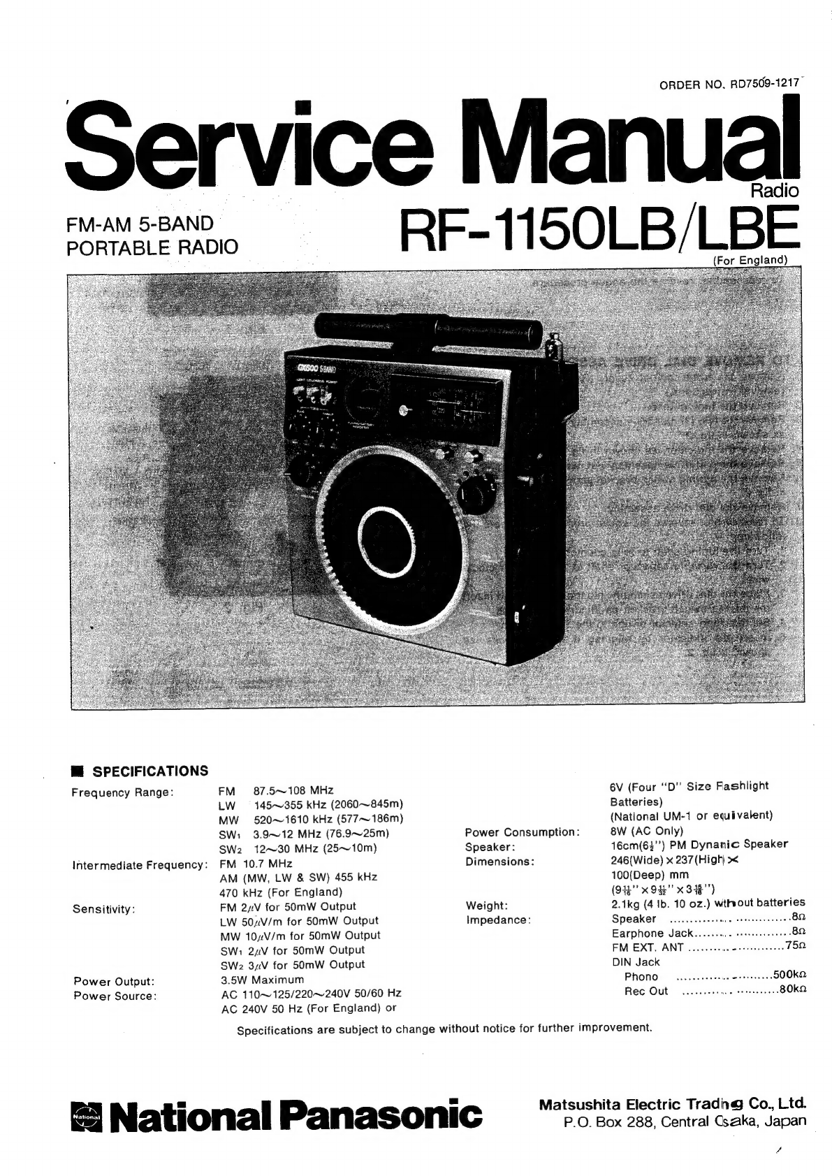
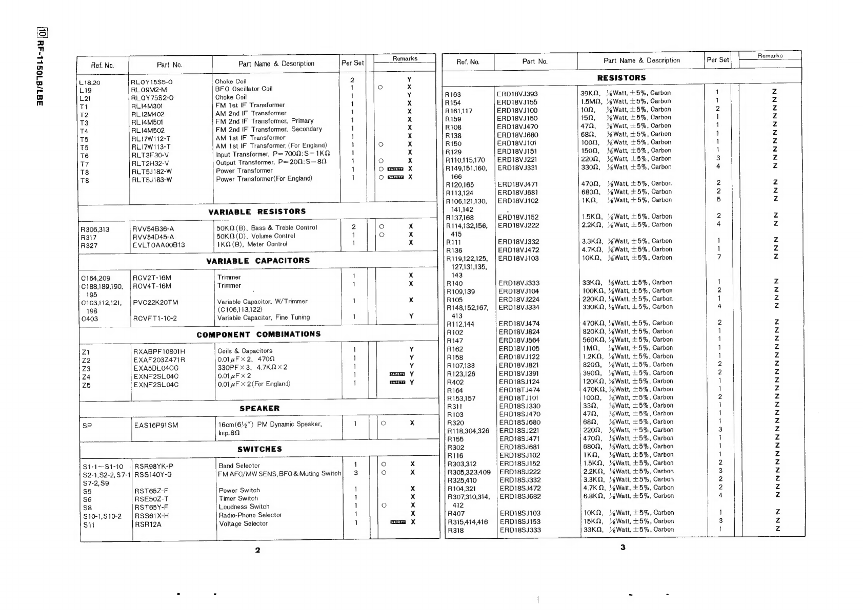
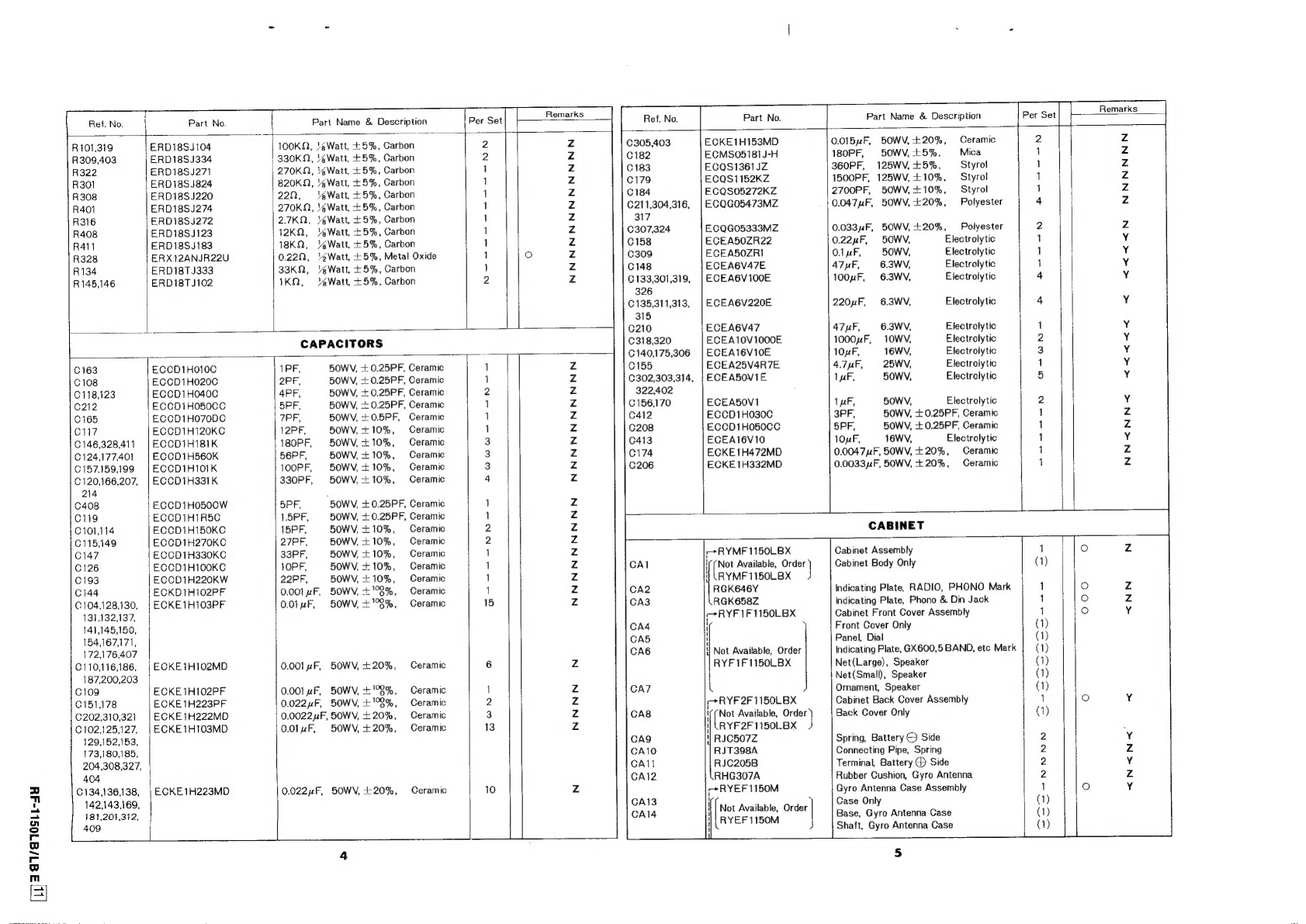
Panasonic RF-1150LB User manual

ORDER
NO.
RD7509-1217-
ervice
Manual
sat
RF-1150LB/LBE
(For
England)
ne
M@
SPECIFICATIONS
Frequency
Range:
FM
87.5~~108
MHz
6V
(Four
“‘D"
Size
Flashlight
LW
=
145~355
kHz
(2060~845m)
Batteries)
MW
520~1610
kHz
(577~
186m)
(National
UM-1
or
equivalent)
SWi
3.9~12
MHz
(76.9~25m)
Power
Consumption:
8W
(AC
Only)
SW2
12~30
MHz
(25~10m)
Speaker:
16cm(6$"’)
PM
Dynamic
Speaker
Intermediate
Frequency:
FM
10.7
MHz
Dimensions:
246(Wide)
x
237
(High)
><
(MW,
LW
&
SW)
455
kHz
100(Deep)
mm
470
kHz
(For
England)
(942
x
945"
x
348")
Sensitivity:
FM
2xV
for
50mW
Output
Weight:
2.1kg
(4
Ib.
10
oz.)
without
batteries
LW
504V/m
for
50mW
Output
Impedance:
Speaker
......
Shs
MW
10V/m
for
50mW
Output
Earphone
Jack.......
SW:
24V
for
50mW
Output
FM
EXT.
ANT...
SWe
3uV
for
50mW
Output
DIN
Jack
Power
Output:
3.5W
Maximum
Phono
7
Power
Source:
AC
110~125/220~240V
50/60
Hz
Rec
Out
......-
AC
240V
50
Hz
(For
England)
or
Specifications
are
subject
to
change
without
notice
for
further
improvement.
we
dN:
i
=
Mat
hita
Electric
Trading
Co.,
Ltd.
National
Panasonic
ee
eee

M@
TO
REMOVE
CABINET
COVER
1.
Remove
the
seven
(7)
control
knobs
(VOLUME,
BASS,
_
TREBLE,
BAND,
BFO,
MUTING
and
FM
AFC/MW
SENS).
(To
remove
those
controls,
wind
a
cord
around
the
control
and
pull
it
outward.)
.
Remove
the
battery
compartment
cover.
.
Remove
the
four
(4)
cabinet
cover
screws
(nos.
1~4),
as
shown
in
fig.
1.
.
Raise
the
gyro
antenna.
.
Remove
both
the
front
and
the
rear
cabinet
covers.
.
Remove
the
sockets
for
lead
wiring
to
the
front
and
rear
cabinet
covers.
.
To
reassemble,
reverse
the
above
procedure.
M@
TO
REMOVE
DIAL
DRIVE
ASSEMBLY
1;
2.
3.
a
Remove
the
front
cabinet
cover.
(Refer
to
cabinet
cover
removal
instructions.)
Remove
the
tuning
knob.
Remove
the
two
(2)
dial
drive
assembly
screws
(nos.
1
&
3),
as
shown
in
fig.
2.
Remove
the
indicator,
as
shown
in
fig.
2.
.
Remove
the
dial
drive
assembly
nut,
as
shown
in
fig.
2.
.
Remove
the
muting
switch
bracket
screws,
no.
2,
as
shown
in
fig.
2.
.
Remove
the
dial
drive
assembly.
.
To
reassemble,
reverse
the
above
procedure
and
note
the
following:
1.
Turn
the
tuning
shaft
to
fully
counter-clockwise.
2.
Turn
the
variable
capacitor
shaft
to
fully
counter
clock-
wise.
3.
Place
the
dial
drive
assembly
into
the
chassis,
and
insert
the
muting
switch
bracket,
as
illustrated
in
fig.
2.
4.
Set
the
band
selector
switch
to
the
SW:
position.
5.
Insert
the
indicator
by
aligning
it
with
the
boss,
as
shown
in
fig.
2.
az!
DIAL
SCALE
INSTALLATION
GUIDE
NO
(2)
.
Insert
the
gear
(the
gear
not
attached
to
the
shaft)
and
the
spring
into
roller
no.
1,
as
shown
in
fig.
3.
.
Fully
wrap
the
dial
scale
around
roller
no.
1,
as
shown
in
fig.
3.
.
Insert
the
dial
scale
into
rib
of
roller
no.
2,
as
shown
in
fig.
3.
.
Loosen
the
dial
drum
screw,
as
shown
in
fig
.3.
.
Using
a
screw-driver,
as
shown
in
fig.
3,
slightly
move
the
gear
of
roller
no.
1
so
that
the
gear
disengages
from
the
center
gear,
turn
three
times
in
the
direction
of
the
arrow
(being
sure
to
secure
roller
no.
1
so as
to
prevent
it
from
also
turning),
and
then
engage
the
gear
with
the
center
gear
once
again.
.
Set
the
start
point
of
the
dial
scale
with
the
rib,
as
shown
in
fig.
4.
.
Turn
the
tuning
shaft
to
fully
counter-clockwise.
.
Tighten
the
dial
drum
screws,
as
shown
in
fig.
3.
RF-1150LB/LBE
©
Screw
No.2
Screw
No.1
(CA37)
(CA37)
Screw
No.3
(CA37)
Fig.
1
Screw
No.1
Screw
No.2
(CH31)
(CHa0)
;
Indicator
(CH32)
ab
Boss
WE
-
Screw
No.3
(CHa1)
Nut
(CH33)
Bracket
Roller
No.2
(CHi2)
Screw-driver
(CHa)

@
DIAL
CORD
INSTALLATION
GUIDE
1.
Remove
the
dial
drive
assembly
from
the
chassis.
(Refer
to
dial
drive
assembly
removal
instructions.)
.
Dial
cord
length
is
47%”.
.
Loosen
the
dial
drum
screw,
as
shown
in
fig.
3.
.
Set
each
dial
drum
at
the
position,
as
shown
in
fig.
5.
.
Arrows
(1~12)
indicate
correct
order
and
direction
of
dial
cord
installation,
as
shown
in
fig.
5.
.
Cement
dial
cord
ends.
.
Turn
the
tuning
shaft
to
fully
counter-clockwise.
8.
Set
the
start
point
of
the
dial
scale
with
the
rib,
as
shown
in
fig.
4.
9.
Tighten
the
dial
drum
screw,
as
shown
in
fig.
3.
on
&
©
PO
NOD
™@
TO
REMOVE
GYRO
ANTENNA
1.
Remove
gyro
antenna
cover
in
the
direction
of
arrow,
as
shown
in
fig.
6.
2.
Unsolder
lead
wires
to
gyro
antenna,
as
shown
in
fig.
7.
3.
To
reassemble,
reverse
the
above
procedure.
M@
TO
REMOVE
GYRO
ANTENNA
CASE
1.
Remove
gyro
antenna
case
U
ring,
as
shown
in
fig.
8.
2.
Remove
the
gyro
antenna.
(Refer
to
gyro
antenna
removal
instructions.)
3.
Remove
the
gyro
antenna
case
in
the
direction
of
arrow,
as
shown
in
fig.
8.
4.
To
remove
gyro
antenna
case
completely,
unsolder
(on
the
side
of
the
PC
board)
lead
wires
to
gyro
antenna,
as
shown
in
fig.
7.
5.
To
reassemble,
reverse
the
above
procedure.
~5-(CA22)
4
Fig.
8
Cord
(CHio)
Drum
(CH2)
-
White
Fig.
6
Sky
Blue
RF-1150LB/LBE
[3]
Mi
ALIGNMENT
INSTRUCTIONS
(1)
(2)
(3)
(4)
(5)
(6)
(7)
(8)
(9)
(10)
(11)
(12)
(13)
(14)
READ
CAREFULLY
BEFORE
ATTEMPTING
ALIGNMENT
Notes:
1.
Set
volume
control
to
maximum.
2.
Set
bass
&
treble
controls
to
maximum.
3.
Set
band
switch
to
MW,
LW,
SW:,
SW2
or
FM.
4.
Set
FM
AFC/MW
SENS
switch
to
OFF.
5.
Set
loudness
switch
to
OFF.
OOND
.
Set
BFO
switch
to
OFF.
.
Set
power
source
voltage
to
6
volts
DC.
.
Set
FM
muting
switch
to
OFF.
Set
fine
tuning
to
center.
SIGNAL
GENERATOR
or
RADIO
DIAL
SWEEP
GENERATOR
SETTING
(VIVA
oe
SCOPE
ADJUSTMENT
REMARKS
CONNECTIONS
|
FREQUENCY
|
(DISTANCE)
Ot
)
LW
ALIGNMENT
Fashion
loop
of
433
hz
Point
of
non-
several
turns
of
wire
‘England
Only)
interference.
|
Output
meter
Ts
(1st
IFT)
Adjust
for
maximum
and
radiate
signal
30%
Mod
(on/about
across
voice
coil.
T2
(2nd_
IFT)
output.
into
loop
of
receiver.
|
with
400
Hz.
600
kHz)
.
Adjust
for
maximum
wom
|
HE
ant
cain
|
eingeat
bobbin”
ig.
;
q
(*1)L12(ANT
Coil)
|
along
ferrite
core.
C195
(OSC
;
;
k
P
Adjust
for
maximum
”
350
kHz
ae
Be
”
Trimmer)
output.
Repeat
steps
(Fig.
15)
C164(ANT
(2)
and
(3).
Trimmer)
MW
ALIGNMENT
:
Adjust
for
maximum
”
550
kHz
550
kHz
“i
Lie
(OSC
Coil)
Gatput
Adjust
Lis
by
Fig.
16
:
moving
coil
bobbin
(Fig.
16)
(*1)L13(ANT
Coil)
|
aiong
ferrite
core.
C188
(OSC
Adi
;
;
just
for
maximum
”
1500
kHz
dae
”
Trimmer)
|
output.
Repeat
steps
(Fig.
17)
C209
(ANT
(4)and
(5)
Trimmer
:
(*1)
Cement
antenna
bobbin
with
wax
after
completing
alignment.
SW1
ALIGNMENT
=|,
-
Connect
to
test
point
through
10
PF.
capacitor.
Common
to
earth.
”
|
Lis
(OSC
Coil)
3.9
MHz
Adjust
for
maximum
3.9
MHz
:
”
(Pig.
18)
La
(ANT
Coil)
|
output.
ne
‘
am
Adjust
for
maximum
:
C1is9(OS
output.
12
MHz
[Fig.
19)
.
=
Trimmer)
|
Repeat
steps
(6)
7).
and
(7)
SWe2
ALIGNMENT
Connect
to
test
point
Lia
(OSC
Coil)
through
10
PF.
42
MHz
12
MHz
4)
Adjust
for
maximum
copes
or.
Common
to
(Fig.
20)
Ls
(ANT
Coil)
output.
28
MH
Ci
an{OSU
;
Adjust
for
maximum
z
rimmer
output.
a
28
MHz
(Fig.
21)
e
C106(ANT
Repeat
steps
(8)
Trimmer)
and
FM-IF
ALIGNMENT
oa
|
Point
of
non-
|
Connect
vert.
Adjust
for
maximum
High
side
thru.
10.7
MHz
interference
amp.
of
scope
to
|
T1
(FM
1st
IFT)
amplitude
and
proper
0.001
4F
to
point
[TP2],
(400
kHz
(on/about
-
|
point
{TP4]
,
Ts
(FM
2nd
IFT)
linearity
between
Common
to
earth.
SWP.)
90
MHz)
Common
to
(Primary)
+100
kHz
markes.
i
:
earth.
(Refer
to
fig.
11)
|
Adjust
Ta
So
that
,
Pe
=
°
Ta
(FM
2nd
IFT)
10.7
MHz
marker
(Secondary)
appears
at
the
center.
(Refer
to
fig.
12)
:
FM-RF
ALIGNMENT
Gane
repaint
‘i
through
F
ummy
Tuni
Output
meter
.
i
antenna.
Common
to
87.2
MHz
uning
gang
|
across
Le
(FMOSC
Goil)
|
{*2)Adjust
for
maxi—
fully
closed.
Voice
Col:
)
mum
output.
earth.
(Refer
to
fig.
13).
u”
90
a
Tune
to
signal.
My
wu”
106
MHz
J
106
MHz
(Fig.
22)
L7
(FM
DET
Coil)
Ci22(FM
OSC
(*
2)Adjust
for
maximum
ouput.
(*
2)Adjust
for
¥
Trimmer)
maximum
ouput.
C113(FM
DET
Repeat
step;
Trimmer)
(12)~(14).
(2)
Three
output
responses
will
be
present;
proper
tuning
is
the
center
frequency.
RF-1150LB/LBE

Schematic
Diagram
—Model
RF-1150LB/LBE
TRi
TRe
TR3
TR4
TRs
TRe.7
TRa
D3
TRo.10
TR22
28K49
=
2801859
2801359
AYDSC-
“19
280829
280829
280829
ogo
280829
OAS0
280829
28C829
WHIP
ANT
FM
RF
AMP
FM
OSC
FM
MIX
FM
IF
AMP
FM-AM
IF
AMP
FM-AM
IF
AMP
AM
DET
FMIF
AMP
FMRECT
~
FMIF
AMP
CW
DET
[TP]
[
)
i
g
3.9V
sav
8
baal
pow
LO
oe
8
‘
&
)
ug
neo
ray
AD
TR4)
ov,
2
TRs
Cian
TRS
fe}
a:
pans
Vv
TRIO
h
.
8
CieC4p
(Ly)
cm
ats
|
R10
220
we)
%
@
©
ogy
ae
Peete
a
8
Chagk2
=
)
(Ye
me
ANT
Si
al
BS
ged
ss
ser
ls
SS
an
bl
bal
lel
SStolow
=
g
ET
iv
RL
Spec]
Ls
i
8
38
sy
Vesey
7g
Stel!
2
for
Ca
$2
giale
Sbebes
oF
<°h
8
af]
72]
o
5
z
x
co]
t
=
;
oS
y
%
i
edn
ieee
ek
aa
ore
ae
)
f
2
0
ry
0.6
mA:
a
6)
: -
ro)
1
+6
5
S-Woai]
tat
ieee
oo
8
oe
of€,
eae
Ti
atiny
A
Oo
O
8
STIS
/
Curie
|@
CrasKIOp
Rios
!Ook
RMt93}{—
|
a
aes:
8
ee
&
rs)
/
0.2mat
-
dl
=
a
aaa
bs
iv
TT
:
:
Sl
8
ee
Se
a
§
6
Ris2
{{M
Cis3MO.01
CIgEa
KOOP
v
C214K330p
|
Eager
—
ie
é
a.
/
q
C1670
|
Raii8k
°
i
Oo
1!
’
ra
/
g
:
5
Poe
ayy
ee
eee
if
3
Oo
pots
13
a
&
|.
4
Biz
ol
|
§
6
iS
eilor
rs
8
Z_SIG
¢
Oo
2.9V
gre
5
1s81-2kK
Rissi5
306
SOKIB),
<
rR
Reossof
[I
4305
2:2k
R:
R312
1-5k
Rais15k
aaa
|
|
i
|
\
-
|
|
28K49
28C1359
RVDVDT25OM
2801859
ASO
2sc828
AVDVUT25OM
2scd0o
2sC945
0945
20945
280828
281568
RVDVDIIS1
RVOVD
ae
!
BSKi8,
3su8ee,
RVOYDI250M
2st90
$8179
280845
280045,
250808
280150
AYDYDLISYRYDVOI2S2L.
RYDNDIEST
RVQIOEILF
101102
103104124123
106 108
109
NO
121139.144
15
116
117
481490421122
125 126
408
127128
129130
131
132
134
133
136
137
Sanu
206
20740242
143
135
144
145
146
147
148
(49
150
151
152
154153
211
214
210
199
200
201 202
203
155
204
156-157
158
159
404
—«
209
163164
165 166
412
16712)
4170
14
172173
194
175 176
177178179
180
208
181
182
183801
1BHB5S
186
187
188
189
190
212193195
198
301
302
303.403
328
304
305 306
3071308
309
3243102819
313
314
327315
316
317
318
311
326
321
all
320-322
|
101
102
103
104
105
488
106
107
414108
109
10
(112
119
14
15
6
18
9
120
121
122
123
12445117
125416126
127
129
130
131
132
133
134
135137
138
162
136
164
163
139
170
165
166
167
140
141
168
142143144
145
146
!
a
147
148149
150
151
152
154
155
156
159
153
158
15°77
160
161
41101302407
303.304
305 306
307309
310311
406
312
409
313
410314
412.315
316
317316
319.320
321
322
323325
326
308
327
328
'
Noles:
i
Di6.17,18.19
1.
Si-1~S1-10:
Band
selector
in
‘‘FM”’
position.
10.
S10-1,
S10-2:
Radio-phono
selector
in
‘‘Radio”’
position.
ug
a
RF-1150LBE
RVDIOFILF
2,
S2-1,
S2-2:
FM
AFC/MW
SENS
switch
in
“ON”
OX"
posi-
11.
S11:
Voltage
selector
in
‘‘'220~240V”
position.
ee
age
(For
England)
|
RECT
|
tion
12.
DC
voltage
measurements
are
taken
with
circuit
tester
7
I
ma
3.
S3:
Dial
light
switch
in
‘‘OFF’’
position.
10ka/V
from
negative
side
of
battery.
JT
SSK
roses,
|
4.
Sa:
AC-Battery
selector
in
‘‘Battery’’
position.
TRi,
2,
3,
4,
8,
9,
10
.......
FM
position
eh
es
thee
5.
Ss:
Power
switch
in
‘‘OFF”’
position.
TR11,
12,13
veeeeeeee
MW
position
Gage
5
!
6.
Se:
Timer
switch
in
‘‘OFF’’
position.
TR22,
23
.......e
cece
eee
BFO
ON
position
18
ow
7.
S7-1,
S7-2:
BFO
switch
in
‘‘OFF”
position.
13.
Battery
current:
No
signal
..............ccccccceeeeee
45mA
nal
les
2G
sus
i
8.
Ss:
Loudness
switch
in
‘‘OFF”’
position.
Maximum
output
..............-
720mA
(iss
2s
33
BE8
3
cle
2388
8
|
9.
Sg:
Muting
switch
in
‘‘OFF”’
position.
14.
Indicates
that
only
parts
specified
by
the
manu-
BOTTOM
VIEW
ie
RF-1150LB/LBE
facturer
be
used
for
replacement
in
critical
circuits.
$2.4
28
leem
(6/2)
[
|
|
—
BATT
b
Jefefa
20k90
ac
_
Rigi
tk
!
oO
2
'
8
sy
506
z
ii
O
Be
Si-3
C
x
OO
ry
p
a
403k
Ol
te
3
v-
OO
Cis6
SOVI
x
8
4.5V
a
8
©
:
O_
=
O
[
TPs}
8
TRay|
ES
ww
‘
N
oO
Rias10k
=
RIi44470K
1
‘
H
4
C156
5OVO.2
m
Ca2250V1
Rao3
300K
cH
5
aaa
UM-1xX4
6V
C320
10V19000
vrcccc-
ne

Circuit
Board
Wiring
View-
Model
RF-1L50LB/LBE
TRi2
TR7
OQOOOL®
|i
@©
|
©@O©
@O®™
GO)
@
yi
TRs
TRg
|
FM
TRio
Cp]
TRi
[Poy
aay
|
TRis
3
OCQOOQO@MOQHOOQOOO
O@
COOOQOVOO
Qe
Liz
LW
ANTENNA
COIL
Lis
MW
ANTENNA
COIL
EXT
ANTENNA
TERMINAL
WHIP
ANTENNA
A
VARIABLE
CAPACITOR
W/
TRIMMER
FM
AFC
&
MW
SENSITIVITY
SWITCH]
MUTING
SWITCH
mee
DIAL
LIGHT
w)
s
rl
C403
$3
@
PL
(©)
FINE
TUNING
(20)
J
R313
50K
(B)
TREBLE
CONTROL
R306
50K(B)
R317
SOK
(D)
BASS
VOLUME
CONTROL
CONTROL
(6cm
(6/2")
PM
DYNAMIC
1
ft
SPEAKER
TERMINAL
[U@U]
EARPHONE
OR
EXT
SPEAKER
JACK
CRYSTAL
JACK
VOLTAGE
SELECTOR
H0~I25V/220~240V
BATTERY
6V
con
ON/OFF
TIMER
EXT
POWER
SOURCE
JACK
SWITCH
W/AC-BATTERY
SELECTOR
DIN
JACK
:
ri
LOUDNESS
SWITCH
©
RF-1150LBA
BBE
6)

1.
Set
band
itch
to
MW.
2.
Set
BFO
itch
to
ON.
eae
aaes
Sete
og
ee
W@
CABINET
PARTS
LOCATIONS
SIGNAL
GENERATOR
or
RADIO
DIAL
SWEEP
GENERATOR
SETTING
CONNECTIONS
A
FREQUENCY
|
(DISTANCE)
(vTVM
oC
SCOPE)
ADJUSTMENT
REMARKS
CA13
CAi5
BFO
ALIGNMENT
geet!
loop
cl
rein
of
non-
|
several
turns
of
wire
interference.
Audio
output
:
and
radiate
signal
435.5
kHz
(on/about
from
speaker.
Lis(BFO
OSC
Coil)
into
loop
of
receiver.
600
kHz)
CAs31
Adjust
for
zero
beat.
M@
BATTERY/TUNING
METER
ADJUSTMENT
1.
RADIO
RECEIVER
SETTING
2.
REMARKS
«
Set
band
switch
to
MW.
+
Adjust
R327
so
that
the
pointer
of
*
Set
volume
control
to
minimum.
level
meter
stays
as
shown
in
»
Set
power
source
voltage
to
6
figure
Fig.9
volts
DC.
Sabin
‘OKT
Fig.
23
AM
tst_
470kHz
455kHz
(England)
MW
OSC
550kHz
Lis
Fig.
11
Fig.
12
AM
2nd
470kHz
A
455kHz
(England)
T
To
SG
(Rias)
(Rise)
["4
(SG
i
9)
moO
134
q
imp.75
(P)
—
7
Sa
(0)
(Seat
Fig.
25
Lio
T3
S)
7
Mond
Fig.
13
FM
Dummy
Antenna
10.7MHz
T4
Fig.
10
Alignment
Points
M
CHASSIS
PARTS
LOCATIONS
To
Receiver
r
|
|
\
CH23
Ss
CHis CHi7
CH37
CHit
MHz
KH
xwkHz
Miz
KHz
kHz
xokHe
MHa
Mie
xokHe
—
MHe MHz
av
U
S
cm
i
a
set
wee
SE
Fig.
14
(145
kHz)
Fig.
16
(550
kHz)
Fig.
18
(3.9
MHz)
Fig.
20
(12
MHz)
Fig.
22
(106
MHz)
(LW)
(MW)
(SW1)
(SW2)
(FM)
MHz
okHt
xXiOKHE
SUI
ESP
AIIIII
CHAN
NEL
MW
Wt
Sw2
Swi
SW2
ANA
Uew
oe
OUANAL
UKW
89-12
12~30
B9~I2
12~30
:
Fig.
27
Fig.
15
(350
kHz)
Fig.
17
(1500
kHz)
Fig.
19
(12
MHz)
Fig.
21
(28
MHz)
RF-1150LB/LBE
RF-1150LB/LBE

(6|
31/8
10sbt-4du
MIREPLACEMENT
PARTS
LIST
---:---::-----
Model
RF-1150LB/LBE
NOTES:
1.Part
numbers
are
indicated
on
most
mechanical
parts.
Please
use
this
part
number
for
parts
orders.
2.X—Z
rank:
X
rank
parts
will
cover
80%
of
repair
needs.
X+-Y
rank
parts
will
cover
95%
of
repair
needs.
Z
rank
parts
are
less
necessary.
3.
umm
Indicates
that
only
parts
specified
by
the
manufacturer
be
used
for
replacement
in
critical
circuits.
Ref.
No.
Part
No.
Part
Name
&
Description
Per
Set
TRANSISTORS
AND
DIODES
TRI11
TR2,3,12,13
TR4,5,6,7,8,9,10
22,23
TR14
TR15,17,18
TRI6
2SK49
2801359
280829
2SC900
280945
28B173
2801568
280828
RVDSC-15
OA90
2-0A90
RVDVD1250M
RVDVD1151
RVDVD1252L
RVD10E1LF
RVD10E1LF
FM
RF
Amplifier,
AM
RF
Amplifier
FM
Oscillator,
FM
Mixer,
AM
Mixer,
AM
Oscillator
FM-AM
IF
Amplifier,
CW
Detector,
BFC
Oscillator
Pre-Amplifier
AF
Amplifier,
Power
Operation
Compensator,
Ripple
Filter
AF
Amplifier
Power
Amplifier
Meter
Amplifier,
FM
Muting
FM
AFC
AM
Detector,
FM
Rectifier,
AM
AGC
FM
Detector
Operation
Compensator
Power
Operation
Compensator,
Switching
Power
Operation
Compensator
Rectifier
Rectifier
(For
England)
NN
OO:
RN
Ni
ge.
><
[sarery]
KK
OK
OK
OK
OOK
KOK
OK
VARIATITES
Val,2
EYV320D1R2J2
Operation
Compensator
2
xX
CERAMIC
FILTERS,
COILS
AND
TRANSFORMERS
CF1,2,3
RVFCF10S12CR
Ceramic
Filter
3
x
L1
RLQY75S5-0
Choke
Coil
1
Y
L2
RLOY25S5-0
Choke
Coil
1
Y.
L4
RLA3M15-K
SW1
Antenna
Coil
1
x
L5
RLA3N13-0
SW2
Antenna
Coil
1
x
L6
RLA4Y6-0
FM
Antenna
Coil
1
x
ti
RLD4N30
FM
Detector
Coil
1
xX
L8
RLO4N22-0
FM
Oscillator
Coil
1
x
L9,10
RLQZ68S1-Y
Choke
Coil
2
Y
Li
RLQY15G5-0
Choke
Coil
1
Y
112,13
RLF6X4-0
LW
&
MW
Antenna
Coil
1
x
L14
RLO3M24-M
SW2
Oscillator
Coil
1
x
L15
RLO3M22-M
SW1
Oscillator
Coil
1
x
L16
RLO2M11
MW
Oscillator
Coil
1
x
L17
RLOIM)
LW
Oscillator
Coil
1
x
|
STVIMALVW
ONDIOVd

3GV/A
10S
1
1-4y
G7
Remarks
=
Part
No.
Part
Name
&
Description
Per
Set
Ref.
No.
Part
No.
Part
Name
&
Description
Per Set
L18,20
RLOY15S5-0
Choke
Coil
2
Y
RESISTORS
L19
RLO9M2-M
BFO
Oscillator
Coil
1
x
L21
RLQY75S2-0
Choke
Coil
1
¥
R163
ERD18VJ393
39K,
leWatt,
£5%,
Carbon
1
z
T1
RLI4M301
FM
1st
IF
Transformer
1
x
R154
ERD18VJ155
15MQ,
‘Watt,
+5%,
Carbon
1
Z
T2
RLI2M402
AM
2nd
IF
Transformer
1
xX
R161,117
ERD18VJ100
100,
M4Watt,
+5%,
Carbon
2
Zz
T3
RLI4M501
FM
2nd
IF
Transformer,
Primary
1
x
R159
ERD18VJ150
150,
Watt,
+5%,
Carbon
1
Z
T4
RLI4M502
FM
2nd
IF
Transformer,
Secondary
1
xX
R108
ERD18VJ470
470,
‘Watt,
+5%,
Carbon
1
Zz
TS
RLI7W112-T
AM
1st
IF
Transformer
1
x
R138
ERD18VJ680
680,
%Watt,
+5%,
Carbon
1
Zz
TS
RLI7W113-T
AM
1st
IF
Transformer,
(For
Engiand)
1
x
Ri50
ERD18VJ101
1000,
Watt,
+5%,
Carbon
1
Zz
T6
RLT3F30-V
Input
Transformer,
P=
7000:S=1KQ
1
xX
R129
ERD18VJ151
1500,
‘Watt,
5%,
Carbon
1
Zz
T7
RLT2H32-V
Output
Transformer,
P=200:S=
80
1
Xx
R110,115,170
|
ERD18VJ221
2200,
Watt,
+5%,
Carbon
3
Zz
T8
RLT5J182-W
Power
Transformer
1
x
R149,151,160,
|
ERD18VJ331
3300,
l4Watt,
+5%,
Carbon
4
Zz
T8
RLT5J183-W
Power
Transformer(For
England)
1
©
mua
X
166
R120,165
ERD18VJ471
4700,
Watt
+5%,
Carbon
2
Zz
|
R113,124
ERD18VJ681
6800,
‘Watt,
+5%,
Carbon
2
Zz
R106,121,130,
|
ERDI8VJ102
1KQ,
Watt,
+5%,
Carbon
5
Zz
VARIABLE
RESISTORS
141,142
P
R137,168
ERD18VJ152
1.5KQ,
‘Watt,
+5%,
Carbon
2
z
R306,313
RVV54B36-A
50KQ(B),
Bass
&
Treble
Control
2
1}
x
R114,132,156,
|
ERDI8VJ222
2.2KN,
Watt,
+5%,
Carbon
4
Z
R317
RVV54D45-A
50KQ(D),
Volume
Control
1
ce)
x
415
R327
EVLTOAA00B13
1KQ(B),
Meter
Control
1
x
R111
ERD18VJ332
3.3KQ,
“Watt,
+5%,
Carbon
j
Zz
R136
ERD18VJ472
4.7KQ,
Watt,
£5%,
Carbon
1
Zz
VARIABLE
CAPACITORS
R119,122,125,
|
ERD1I8VJ103
1OKQ,
Watt,
+5%,
Carbon
7
Zz
——y
127,131,135,
C164,209
RCV2T-16M
Trimmer
1
x
143
C188,189,190,
|
RCV4T-16M
Trimmer
x
R140
ERD18VJ333
33KQ,
l4Watt,
+5%,
Carbon
1
Z
195
R109,139
ERD18VJ104
100KQ,
'Watt,
+5%,
Carbon
2
Zz
C103,112,121,
|PVC22K20TM
Variable
Capacitor,
W/Trimmer
1
x
R105
ERD18VJ224
220KQ,
Watt,
+5%,
Carbon
1
Zz
198
(C106,113,122)
R148,152,167,
|
ERD18VJ334
330KNQ,
Watt,
+5%,
Carbon
4
z
C403
RCOVFT1-10-2
Variable
Capacitor,
Fine
Tuning
1
Y
413
R112,144
ERD18VJ474
470KQ,
Watt,
£5%,
Carbon
2
Zz
COMPONENT
COMBINATIONS
R102
ERD18VJ824
820KQ,
‘Watt,
£5%,
Carbon
1
Z
——-
R147
ERD18VJ564
560K,
4Watt,
+5%,
Carbon
1
z
Z1
RXABPF
10801H
Coils
&
Capacitors
1
Ea
R162
ERD18VJ105
1MQ,
‘Watt,
+5%,
Carbon
1
Zz
Z2
EXAF203Z471R
O.0luF
x2,
4709
1
Y
Ri58
ERD18VJ122
1.2KQ,
‘Watt,
+5%,
Carbon
i
Z
Z3
EXA5DLO4CG
330PFX3,
4.7KQX2
1
Y
R107,133
ERD18VJ821
8200,
lWatt,
+5%,
Carbon
2
Z
Z4
EXNF2SL04C
0.01
pF
x
2
1
mum
Y
R123,126
ERD18VJ391
3900,
l4Watt,
+5%,
Carbon
2
Zz
Z5
EXNF2SL04C
0.01
#F
X
2(For
England)
1
Y
R402
ERD18SJ124
120KQ,
%
Watt,
+5%,
Carbon
1
zZ
R164
ERD18TJ474
470KQ,
'4Watt,
£5%,
Carbon
1
Zz
R153,157
ERD18TJ101
1000,
‘Watt,
+5%,
Carbon
2
Zz
SPEAKER
R311
ERD18SJ330
332,
‘Watt,
+5%,
Carbon
1
Zz
t
R103
ERD18SJ470
47Q,
eWatt,
5%,
Carbon
1
Zz
SP
EAS16P91SM
16cm(61%")
PM
Dynamic
Speaker,
1
O°
x
R320
ERD18SJ680
680,
'4Watt,
=5%,
Carbon
1
Zz
Imp.82
R118,304,326
|
ERD18SJ221
2200,
‘Watt,
=5%,
Carbon
3
zZ:
+
R155
ERD18SJ471
4702,
}¢Watt,
+5%,
Carbon
1
Z
SWITCHES
R302
ERD18SJ681
6800,
leWatt,
+5%,
Carbon
1
Zz
R116
ERD18SJ102
1KQ,
Watt,
+5%,
Carbon
1
Zz
S1-1~S$1-10
-|RSR98YK-P
Band
Selector
J
ie)
x
R303,312
ERD18SJ152
15KQ,
MWatt,
+5%,
Carbon
2
Zz
$2-1,$2-2,S7-1]
RSS140Y-G
FM
AFC/MW
SENS,
BFO
&
Muting
Switch}
3
fe)
x
R305,323,409
|
ERD18SJ222
2.2K,
Watt,
+5%,
Carbon
3
Zz
$7-2,S9
R325,410
ERD18SJ332
3.3KQ,
Watt,
+5%,
Carbon
2
Zz
$5
RST65Z-F
Power
Switch
1
x
R104,321
ERD18SJ472
4.7K
Q,
YeWatt,
+5%,
Carbon
2
z
S6
RSE50Z-T
Timer
Switch
1
x
R307,310,314,
|
ERD18SJ682
6.8K, Watt,
+5%,
Carbon
4
Zz
$8
RST65Y-F
Loudness
Switch
1
oO
xX
412
$10-1,510-2
RSS61X-H
Radio-Phono
Selector
1
x
R407
ERD18SJ103
10KQ,
Watt,
+5%,
Carbon
]
Zz
$11
RSR12A
Voltage
Selector
1
x
R315,414,416
|
ERD18SJ153
15KQ,
‘Watt,
5%,
Carbon
3
Z
R318
ERD18SJ333
33KQ,
l4Watt,
+5%,
Carbon
1
Zz
3
[
Remarks
—_|

P]
nn
t
=
—_
or
i=]
r
we)
~
r
i]
m
—_
rs
Ref.
No.
Part
No.
Part
Name
&
Description
Per Set
Ref.
No.
Part
No.
Part
Name
&
Description
Per Set
Remarks
R101,319
ERD18SJ104
100KQ,
'eWatt,
+5%,
Carbon
2
Zz
C305,403
ECKE1H153MD
0.015uzF,
SOWV,+20%,
Ceramic
2
Zz
R309,403
ERD18SJ334
330KQ,
}4Watt,
£5%,
Carbon
2
Z
C182
ECMS05181J-H
180PF,
SOWV,+5%,
Mica
1
Zz
R322
ERD18SJ271
270KQ,
'gWatt,
+5%,
Carbon
1
Zz
C183
ECQS1361JZ
360PF,
125WV,+5%,
Styrol
1
Zz
R301
ERD18SJ824
820KQ,
4Watt,
+5%,
Carbon
1
rs
C179
ECQS1152KZ
1500PF,
125WV,+10%,
Styrol
4
z
R308
ERD18SJ220
220,
‘Watt,
+5%,
Carbon
1
Z
C184
ECQS05272KZ
2700PF,
5OWV,+10%,
Styrol
J
Zz
R401
ERD18SJ274
270KQ,
'eWatt,
£5%,
Carbon
1
Zz
211,304,316,
|
ECQG05473MZ
0.047uF,
5OWV,
20%,
Polyester
4
Zz
R316
ERD18SJ272
2.7KQ,
VeWatt,
5%,
Carbon
1
Z
317
R408
ERD18SJ123
12KQ,
‘Watt,
£5%,
Carbon
1
Zz
C307,324
ECQG05333MZ
0.033uF,
5OWV,+20%,
Polyester
2
Zz
R411
ERD18SJ183
18KQ,
Watt,
£5%,
Carbon
1
Zz
C158
ECEAS50ZR22
0.22uF,
BOWV,
Electrolytic
1
Y
R328
ERX12ANJR22U
0.220,
‘Watt,
+5%,
Metal
Oxide
1
Zz
C309
ECEA5OZRI1
O.1
nF,
50WV,
Electrolytic
1
Y
R134
ERD18TJ333
33KQ,
Watt,
+5%,
Carbon
1
Z
C148
ECEA6V47E
47
pF,
6.3WV,
Electrolytic
]
Y
R145,146
ERD18TJ102
1KQ,
SeWatt,
£5%,
Carbon
2
Zz
C133,301,319,
|
ECEA6V1I00E
100unF,
6.3WV,
Electrolytic
4
Y
326
C135,311,313,
|
ECEA6V220E
220uF,
6.3WV,
Electrolytic
Y
315
—
pans
C210
ECEA6V47
47
pF,
6.3WV,
Electrolytic
1
Y
CAPACITORS
C318,320
ECEA10V1000E
1000uF,
10WV,
Electrolytic
2
Y
i
C140,175,306
|
ECEAI6V10E
10pF,
16WV,
Electrolytic
3
Y
0163
ECCD1HO10C
LPF;
5OWV,
+
0.25PF,
Ceramic
]
Z
C155
ECEA25V4R7E
4.7
pF,
25WV,
Electrolytic
1
Y
C108
ECCD1H020C
2PF,
BOWV,
+0.25PF,
Ceramic
1
Zz
302,303,314,
|
ECEASOV1E
TF,
5OWV,
Electrolytic
5
Y
C118,123
ECCD1HO40C
4PF,
B5OWV,
+
0.25PF,
Ceramic
2
Zz
322,402
C212
ECCDIHO50CC
SPF,
BOWV,
=
0.25PF,
Ceramic
1
Zz
C156,170
ECEASOV1
TF,
50OWV,
Electrolytic
2
Y
C165
ECCD1HO70DC
TPE;
BSOWV,
+0.5PF,
Ceramic
1
Z
C412
ECCD1HO030C
3PF,
BSOWV,
+0.25PF,
Ceramic
1
z
C1i7
ECCD1H120KC
12PF,
5OWV,
+10%,
Ceramic
1
Zz
C208
ECCD1HO50CC
5PF,
5OWV,
+0.25PF,
Ceramic
1
Zz
C146,328,411
|
ECCDIH181K
180PF,
S5OWV,+10%,
Ceramic
3
Zz
C413
ECEA16V10
104F,
16WV,
Electrolytic
1
Y
C124,177,401
|
ECCDIH560K
56PF,
BOWV,
+10%,
Ceramic
3
Zz
C174
ECKE1H472MD
0.0047
F,
5OWV,
+20%,
Ceramic
1
Zz
C157,159,199
|
ECCDIHIO1K
100PF,
50WV,+10%,
Ceramic
3
4
C206
ECKE1H332MD
0.0033
uF,
50WV,
+20%,
Ceramic
1
z
C120,166,207,
|
ECCD1IH331K
330PF,
5OWV,+10%,
Ceramic
4
z
214
.
C408
ECCD1HO50CW
5PF,
5OWV,
+0.25PF,
Ceramic
1
Z
C119
ECCD1HIR5C
LSP,
5OWV,
+
0.25PF,
Ceramic
1
Zz
C101,114
ECCD1H150KC
15PF,
B5OWV,
£10%,
Ceramic
2
Zz
CABINET
C115,149
ECCD1H270KC
27PF,
B5OWV,
+10%,
Ceramic
2
z
——-
C147
ECCD1H330KC
33PF,
5OWV,
+10%,
Ceramic
1
z
-+RYMF1150LBX
Cabinet
Assembly
1
ce)
z
C126
ECGCD1H100KC
1OPF,
5OWV,
+10%,
Ceramic
1
Zz
CAl
(ao
Available,
eal
Cabinet
Body
Only
(1)
C193
ECCD1H220KW
22PF,
B5OWV,
£10%,
Ceramic
1
Z
RYMF1150LBX
C144
ECKD1H102PF
0.001
nF,
5OWV,+'%,
Ceramic
1
Z
CA2
RGK646Y
Indicating
Plate,
RADIO,
PHONO
Mark
1
fe)
Zz
C104,128,130,
|
ECKE1H103PF
O.01uF,
SOWV,+'°%,
Ceramic
15
Z
CA3
RGK658Z
Indicating
Plate,
Phono
&
Din
Jack
1
©
Zz
131,132,137,
*RYF1F1150LBX
Cabinet
Front
Cover
Assembly
1
oO
Y
141,145,150,
CA4
{
Front
Cover
Only
(1)
154,167,171,
CAS
'
Panel,
Dial
(1)
172,176.407
CA6
{|
Not
Available,
Order
Indicating
Plate,
GX600,5
BAND,
etc
Mark
(1)
C110,116,186,
|
ECKE1HIO02MD
0.001
uF,
5OWV,
20%,
Ceramic
6
Zz
RYF1F1150LBX
Net(Large),
Speaker
1)
187,200,203
Net(Small),
Speaker
(1)
C109
ECKE1H102PF
0.001
uF,
BSOWV,
+'°%,
Ceramic
]
Zz
CA7
Ornament,
Speaker
(1)
C151,178
ECKE1H223PF
0.022uF,
S5OWV,+'3%,
Ceramic
2
z
r>RYF2F1150LBX
Cabinet
Back
Cover
Assembly
1
ce)
Y
C202,310,321
|
ECKE1H222MD
0.0022uF,
50WV,
+20%,
Ceramic
3
Zz
CA8
ee
Available,
saad
Back
Cover
Only
(1)
C102,125,127,
|
ECKE1H103MD
O0.01unF,
SOWV,+20%,
Ceramic
13
Zz
!
RYF2F1150LBX
:
129,152,153,
CAQ
|
RJC507Z
Spring,
Battery
©
Side
2
Y
173,180,185,
CA10
RJT398A
Connecting
Pipe,
Spring
2
Z
204,308,327,
CAI
RJC205B
Terminal,
Battery
@
Side
2
Y
404
CAI2
RHG307A
Rubber
Cushion,
Gyro
Antenna
2
Zz
C134,136,138,
|
ECKE1H223MD
0.022uF,
SOWV,+20%,
Ceramic
10
Zz
->RYEF1150M
Gyro
Antenna
Case
Assembly
1
°
Y
142,143,169,
CA13
‘
Case
Onl
1
181,201,312,
CAI4
is
Available,
ait
Base,
ee
Antenna
Case
-
409
RYERTIEOM
Shaft,
Gyro
Antenna
Case
Se
|

aa
VE10StL-4y
Zi
[-
cans
ee
Ser
aa
ueder
ul
paqulid
IX
‘3X
‘Ox
@
dy
6
—
Ref.
No.
Part
No.
Part
Name
&
Description
Per
Set
Hemarks
Ref.
No.
Part
No.
Part
Name
&
Description
Per
Set
[Remarks
|
CA15
;
RGK653Z
Indicating
Plate
1
Zz
CH13(Fig.3)
RDG5638Y
Gear,
Dial
Scale
Shaft
(Low
Frequency
1
Oo
Zz
CAI6
'
RHE
25Z
Steel
Ball
1
Zz
Side)
CA17
RUS204Z
Spring,
Steel
Ball
1
Zz
CH14(Fig.3)
RDG5638Z
Gear,
Dial
Scale,
Shaft
(High
Frequency
]
O°
Zz
CA18
4
RUL336Z
Bracket,
Stee!
Ball
1
Z
Side)
CA19
XTN3+
8B
Screw,
Bracket
M’tg
1
Z
CH15(Fig.3)
RDS5201Z
Spring
Gear
(RDG5638Z)
1
Y
CA20
RUL389Z
Bracket,
Gyro
Antenna
Case
1
Z
->RXEF1150N
Gyro
Antenna
Stopper
Assembly
1
co)
z
CA21
RDX310Z
Shaft,
Gyro
Antenna
Case
1
Zz
(Not
Available,
a
Stopper
Only
(1)
CA22
XWA5B
Washer,
Gyro
Antenna
Case
1
Z
RXEF1150N
Bracket,
Stopper
(1)
CA23
XWES5D
Washer,
Gyro
Antenna
Case
1
Z
CH16
RJS75Z-H
Din
Jack,
Phono
&
Tape
1
x
CA24
XWS8AW
Washer,
Gyro
Antenna
Case
1
Zz
CH17
XAMRQ6T
150B
Pilot
Lamp,
Dial
Light,
6V,
0.1A
1
°
x
CA25
XNS8
Nut,
Gyro
Antenna
Case
1
Zz
CH18
RSM2605B-K
Meter,
Tuning
&
Battery
Indicator
1
x
CA26
XUE5FP
U
Ring,
Gyro
Antenna
Case
1
Zz
CH19
RJF1044Y
Terminal,
EXT.
Antenna
1
°
Y
CA27
rRYTF1150M
Timer
Knob
Assembly
1
Y
CH20
RJJ30Z-H
Jack,
EXT.
Power
Source
1
oma
~=Y
Not
Available,
oreer)
Knob
Only
)
CH21
RJJ87Y-C
Jack,
Crystal
&
Earphone
1
x
RYTFt150M
Spring,
Knob
)
RJT
463Z
Spring,
Dial
Light
Switch
1
[e)
Zz
CA28
XEART196F
BY
Whip
Antenna,
6
Steps
1044mm
1
x
CH22
RJE10Z
Cover,
EXT.
Power
Source
Jack
1
om
Z
RMA136Z
Bracket,
Whip
Antenna
1
ie}
Zz
CH23
RUV409Z
Cover,
Power
&
Loudness
Switch
1
fe)
Zz
CA29
RKK102Z
Cover,
Battery
Compartment
1
o)
x
CH24
RUV98A
Cover,
Voltage
Selector
1
Z
CA30
RKE140Z
Cover,
Gyro
Antenna
1
x
CH25
RMW119Z
Bracket,
Muting
Switch
1
Zz
CA3)
RBC105Z2
Button,
Dial
Light
Switch
1
°O
Zz
CH26
RBT75Z
Knob,
Fine
Tuning
1
Zz
CA32
RBD49Y
Knob,
AFC,
BFO
&
Muting
Switch
3
Oo
x
CH27
RHG990Z
Rubber
Cushion,
Timer
2
[o)
Z
CA33
RBN314Z
Knob,
Tuning
1
oO
x
CH28
RHR132Z
Holder
(Small),
Antenna
Lead
Wires
1
fe)
Z
CA34
RBN315Z
Knob,
Bass
&
Treble
2
oO
x
CH29
RHR133Z
Holder(Large),
Antenna
Lead
Wires
1
Oo
Z
CA35
RBS92ZK
Knob,
Band
Selector
1
[o)
x
XSN2+4
Screw,
Muting
Switch
M’tg
1
Z
CA36
RBS98Z
Knob,
Volume
1
°
xX
CH30(Fig.2)
XSN2+5
Screw,
AFC,
Muting
&
BFO
Switch
3
Zz
XWVR10
Washer,
Whip,
Antenna
1
Zz
M'tg
RHR750Z
insulating
Plate,
Whip
Antenna
1
Z
XSN26+
6
Screw,
Variable
Capacitor
M’tg
2
Zz
CA37(Fig.1)
XTB3+50BFN
Serew,
Cabinet
Cover
M’tg
4
Y
CH3!1
(Fig.2)
XTN3+
10B
Screw,
Dial
Scale
Assembly
M’tg
3
Zz
RGT478Y
Name
Plate(
Small),
(For
England)
1
Zz
CH32
RGX651Z
Indicator,
Band
Selector
1
Zz
RGT478Z
Name
Plate
(For
Italy)
1
Z
CH33(Fig.2)
XNS8
Nut,
Bracket
M’tg
1
Z
RGT479Z
Name
Plate(Large),
(For
England)
1
Zz
CH34
RMKQ1ZS
Bracket,
Din
Jack
1
(e)
Z
RJR18B
Lead
Holder(1
Terminal),
P.C.
Board
]
Zz
RUV217A
Cover,
Radio-Phono
Selector
1
Zz
RMY75Z
Heat
Sink,
Transistor
1
Zz
b
ae
XBA2CO8TRO
Fuse,
(For
England)
1
Y
CHASSIS
RJF7A
Holder,
Fuse,
(For
England)
2
Y
RJT514Z
Terminal,
Whip
Antenna
1
Oo
z
rRYDF1150LBX
Dial
Scale
Assembly
RUV364Z
Cover,
AFC
Switch
1
1o)
Zz
CHI
H
(Not
Available,
el
Base
Only
RHR797Z
Cushion,
Core
Antenna
2
©)
Z
|
LRYDF1150LBX
CH2(Fig.5)
|
RDD200Z
Drum(Small),
Dial
1
Y
A
CH3(Fig.3)
||
RDG5639Z
Gear,
Dial
Drum(RDD200Z)
1
Y
ACCESSORIES
CH4
(Fig.3)
|
XTW3+
10E
Screw,
Dial
Drum
M’tg
1
Zz
|
XWC3B
Washer,
Dial
Drum
M’tg
1
Z
XEH1A1
Magnetic
Earphone
1
Y
CHS
i
RDT1251Z
Shaft,
Tuning
1
Zz
RJA20Z-K
AC
Cord,
Power
Source
1
Y
|
XNGR6
Nut,
Tuning
Shaft
M’tg
1
Zz
RJA43Z-K
AC
Gord,
Power
Source
(For
England)
1
Y
|
XWE6D10
Washer,
Tuning
Shaft
M’tg
1
Zz
RQC9011Z
Belt
1
Z
1
XWA6B
Washer,
Tuning
Shaft
M’tg
1
Z
|
XUC4FW
E
Ring,
Gear(RDG5639Z)
M’tg
1
Zz
PACKING
MATERIALS
CH6
RDY31A
Shaft,
Pulley
2
Zz
CH7
RDR20-3
Pulley,
Dial
2
z
RPP168Z
Polyethylene
Cover
1
Z
CH8(Fig.5)
RODD410Y
Drum(Large),
Dial
1
Y
-+RPN9Q176Z
Pad
Complete
1
Zz
CH9(Fig.5)
RDS4060A
Spring,
Drum
2
Y
Not
Available,
Order
Pad,
Right
Side
a
CH10(Fig.5)
RDZO5A
Cord(500m),
Dial
1
Roll
Y
RPN9176Z
}
Pad,
Left
Side
1
CH11
RKD356W
Scale,
Dial
1
Y
ROX5894Z
instruction
Book
1
CH12(Fig.3)
RDF971Z
Roller,
Dial
Scale
2
Z
RPG1507Z
Packing
Case
1
7
This manual suits for next models
1
Other Panasonic Portable Radio manuals

Panasonic
Panasonic RF-D10 User manual

Panasonic
Panasonic R-5410B User manual

Panasonic
Panasonic RF-800UGA User manual

Panasonic
Panasonic EY37A2 User manual

Panasonic
Panasonic RF-3100 User manual

Panasonic
Panasonic RF-2900 User manual

Panasonic
Panasonic RF-1105LBS User manual

Panasonic
Panasonic RF-2900LBS User manual

Panasonic
Panasonic RF-2200 User manual

Panasonic
Panasonic RF-877 User manual