Type
Item
Ralay output type
AC type AC/DC type
100 to 240 V AC, 24 V AC,
24 V AC/DC
50/60 Hz common
Max. 10 V A
5 A, 250 V AC (resistive load)
9.999 s, 99.99 s, 999.9 s, 9999 s, 99 min 59 s, 999.9 min, 99 h 59 min, 999.9 h (selected by DIP switch)
Addition (UP)/Subtraction (DOWN)
(2 directions selectable by DIP switch)
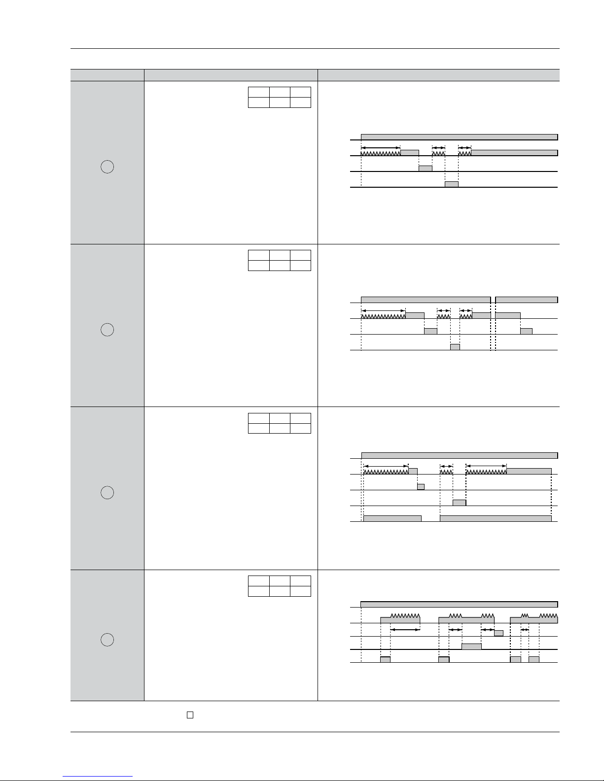
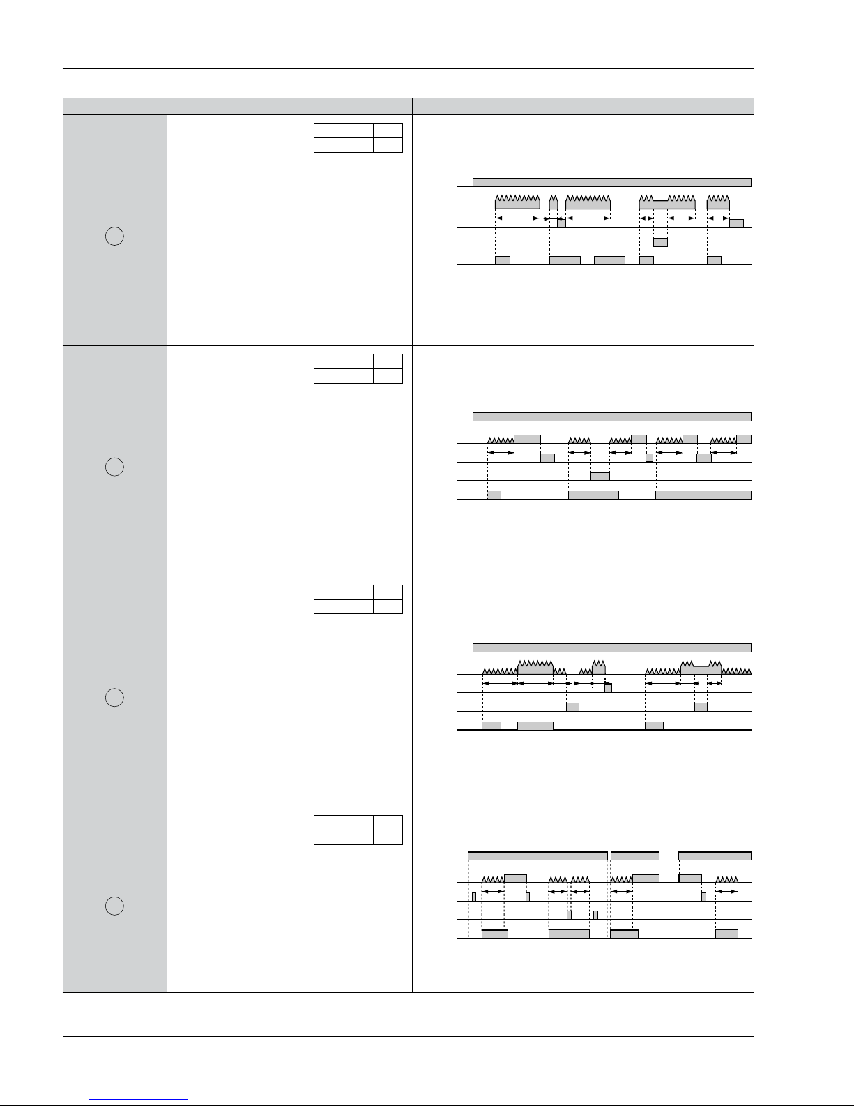
A (Power ON delay 1), A2 (Power ON delay 2), B (Signal ON delay), C (Signal OFF delay), D (Pulse one-shot),
E (Pulse ON delay), F (Signal Flicker), G (Totalizing ON delay) (selectable by DIP switch)
Min. input signal width: 1 ms, 20 ms (2 directions by selected by DIP switch) (The 8-pin type does not have a stop input.)
Min. input signal width: 20 ms (The 8-pin type does not have a lock input.)
Open collector input Input impedance: Max. 1 kΩ; Residual voltage: Max. 2 V
Open impedance: 100kΩor less, Max. energized voltage: 40V DC
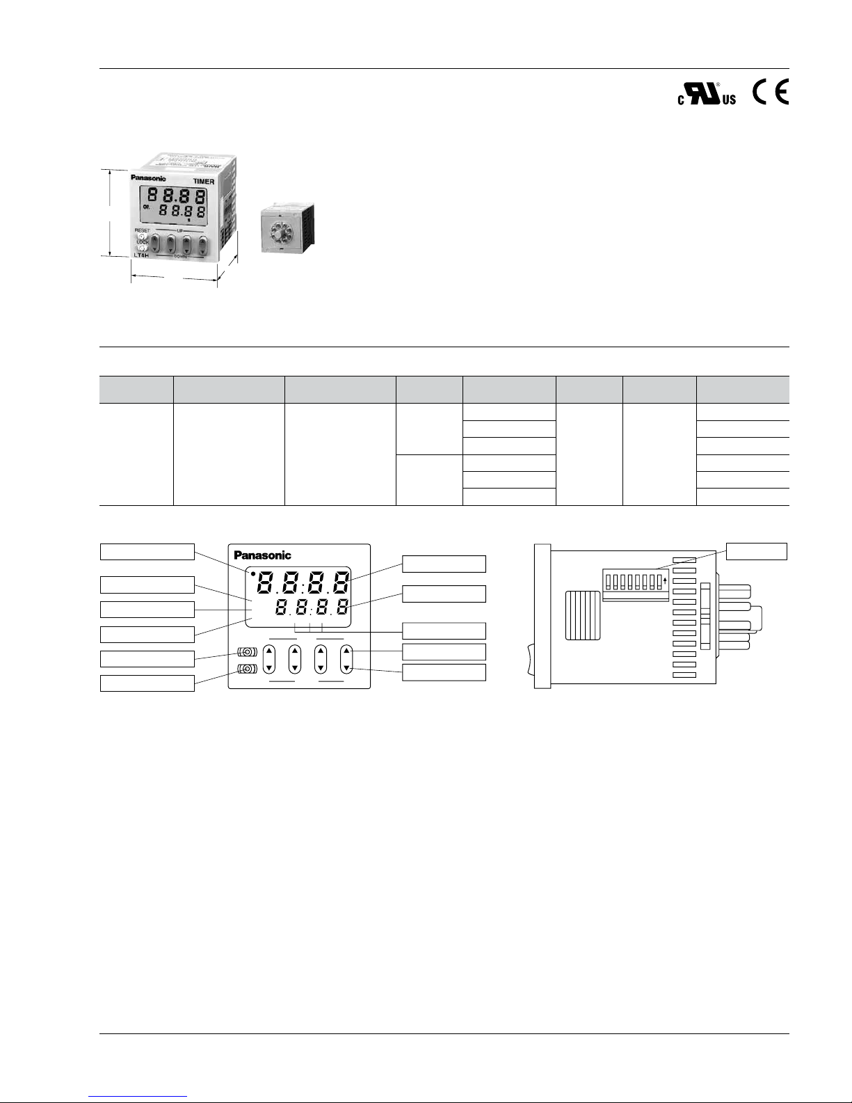
7-segment LCD (LT4H, LT4H-L common), Elapsed value (backlight red LED), Setting value (backlight yellow LED)
EEP-ROM (Min. 105overwriting)
±(0.005 % + 50 ms) in case of power on start
±(0.005 % + 20 ms) in case of input signal start
Operating voltage: 85 to 110%
Temperature: –10 to +55°C +14 to +131°F
Min. input signal width: 1ms
Timed-out 1 Form C
100 mΩ(at 1 A 6 V DC)
Ag alloy/Au flash
Min. 2 ×10⁷ope. (Except for switch operation parts)
1.0 ×10⁵ope. (At rated control voltage)
85 to 110 % of rated operating voltage
2,000 Vrms for 1 min: Between live and dead metal parts (Pin type)
2,000 Vrms for 1 min: Between input and output
2,000 Vrms for 1 min: Between live and dead metal parts (11-pin)
2,000 Vrms for 1 min: Between input and output
1,000 Vrms for 1 min: Between contacts
Between live and dead metal parts
Min. 100 MΩ:Between input and output (At 500V DC)
Between contacts
Min. 100 MΩ:Between live and dead metal parts
Between input and output (At 500V DC)
Max. 0.5 s
10 to 55 Hz: 1 cycle/min single amplitude of 0.35 mm .014 inch (10 min on 3 axes)
10 to 55 Hz: 1 cycle/min single amplitude of 0.75 mm .030 inch (1 h on 3 axes)
Timed-out 1 Form A (Open collector)
—
—
—
Min. 107ope. (At rated control voltage)
12 to 24 V DC
—
Max. 3 W
100 to 240 V AC, 24 V AC,
24 V AC/DC
50/60 Hz common
Max. 10 V A
100 mA, 30 V DC
12 to 24 V DC
—
Max. 3 W
DC type
Transistor output type
AC type AC/DC type DC type
Rating
Time
accuracy
(max.)
Contact
Life
Electrical
Mechanical
Operating
conditions
Rated operating voltage
Rated frequency
Rated power consumption
Rated control capacity
Time range
Time counting direction
Operation mode
Start/Reset/Stop input
Lock input
Input signal
Indication
Power failure memory
method
Operating time fluctuation
Temperature error
Voltage error
Setting error
Contact arrangement
Contact resistance (Initial value)
Contact material
Mechanical (contact)
Electrical (contact)
Allowable operating voltage range
Breakdown voltage
(Initial value)
Insulation resistance
(Initial value)
Operating voltage reset
time
Max. 65° C
(under the flow of nominal operating current at nominal voltage)
—Temperature rise
Functional
Destructive
Vibration
resistance
Min. 98 m 321.522 ft./s2(4 times on 3 axes)
Min. 294 m 964.567 ft./s2(5 times on 3 axes)
–10° C to 55° C +14° F to +131° F
Max. 85 % RH (non-condensing)
860 to 1,060 h Pa
—
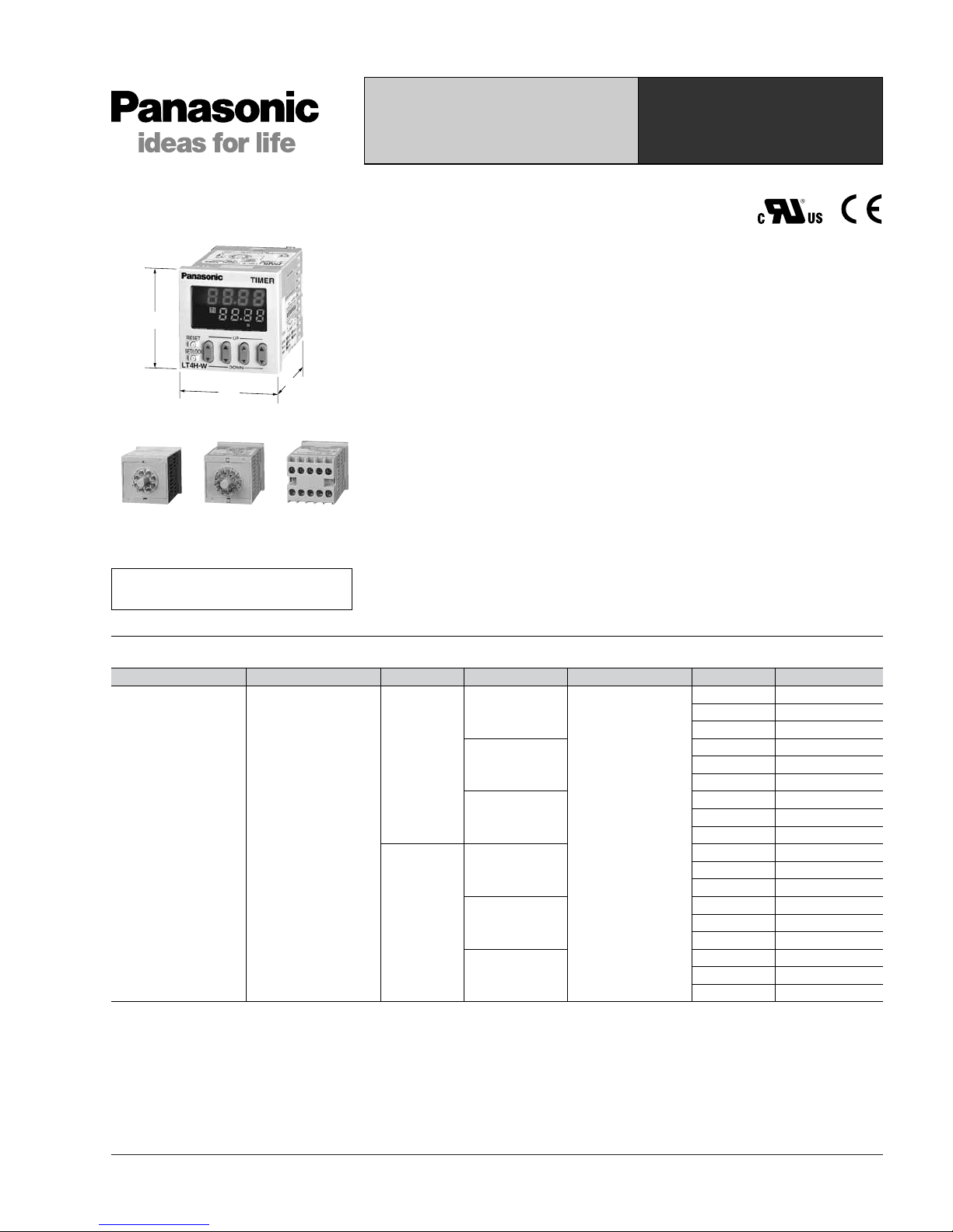
8-pin/11-pin/screw terminal
IP66 (front panel with rubber gasket)
20 % or less — 20 % or less
Functional
Destructive
Ambient temperature
Ambient humidity
Air pressure
Ripple rate
Connection
Protective construction
Shock
resistance
Specifications
[]
LT4H/-L
Applicable standard
Safety standard EN61812-1 Pollution Degree 2/Overvoltage Category II
EMC
(EMI)EN61000-6-4
Radiation interference electric field strength
Noise terminal voltage
(EMS)EN61000-6-2
Static discharge immunity
RF electromagnetic field immunity
EFT/B immunity
Surge immunity
Conductivity noise immunity
Power frequency magnetic field immunity
Voltage dip/Instantaneous stop/Voltage fluctuation immunity
EN55011 Group1 ClassA
EN55011 Group1 ClassA
EN61000-4-2 4 kV contact
8 kV air
EN61000-4-3 10 V/m AM modulation (80 MHz to 1 GHz)
10 V/m pulse modulation (895 MHz to 905 MHz)
EN61000-4-4 2 kV (power supply line)
1 kV (signal line)
EN61000-4-5 1 kV (power line)
EN61000-4-6 10 V/m AM modulation (0.15 MHz to 80 MHz)
EN61000-4-8 30 A/m (50 Hz)
EN61000-4-11 10 ms, 30% (rated voltage)
100 ms, 60% (rated voltage)
1,000 ms, 60% (rated voltage)
5,000 ms, 95% (rated voltage)