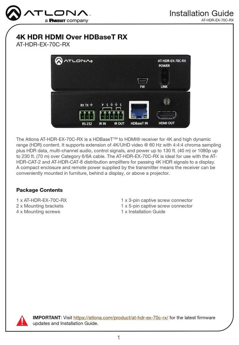
Panduit Atlona AT-HDR-EX-100CEA-RX User manual
Other Panduit Network Hardware manuals
Panduit
Panduit smartzone G5 User manual
Panduit
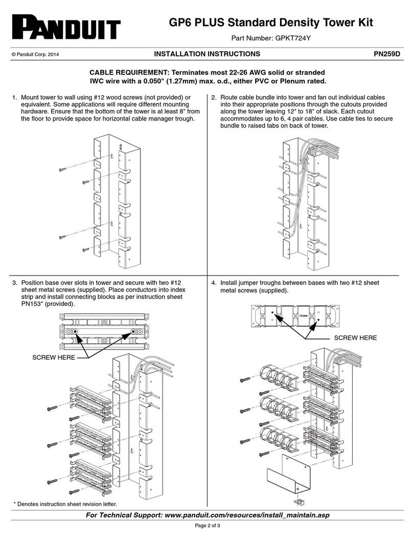
Panduit DPOE24U1XG User manual
Panduit
Panduit GP6 Plus User manual

Panduit
Panduit M1 User manual
Panduit
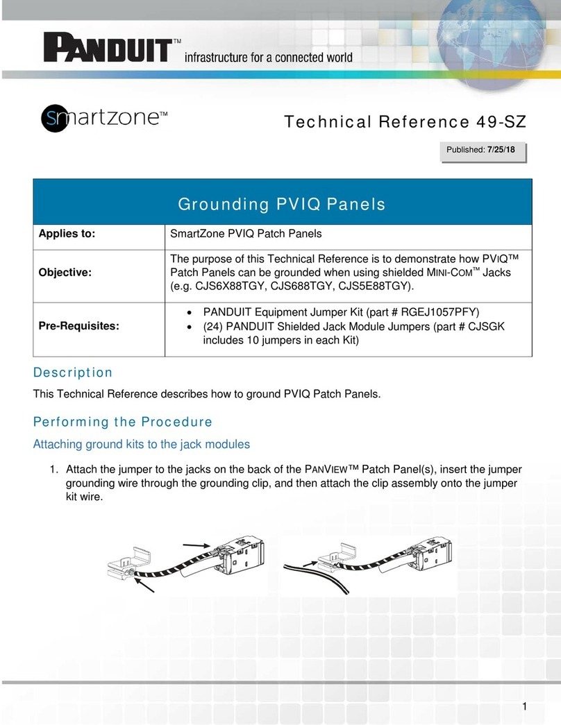
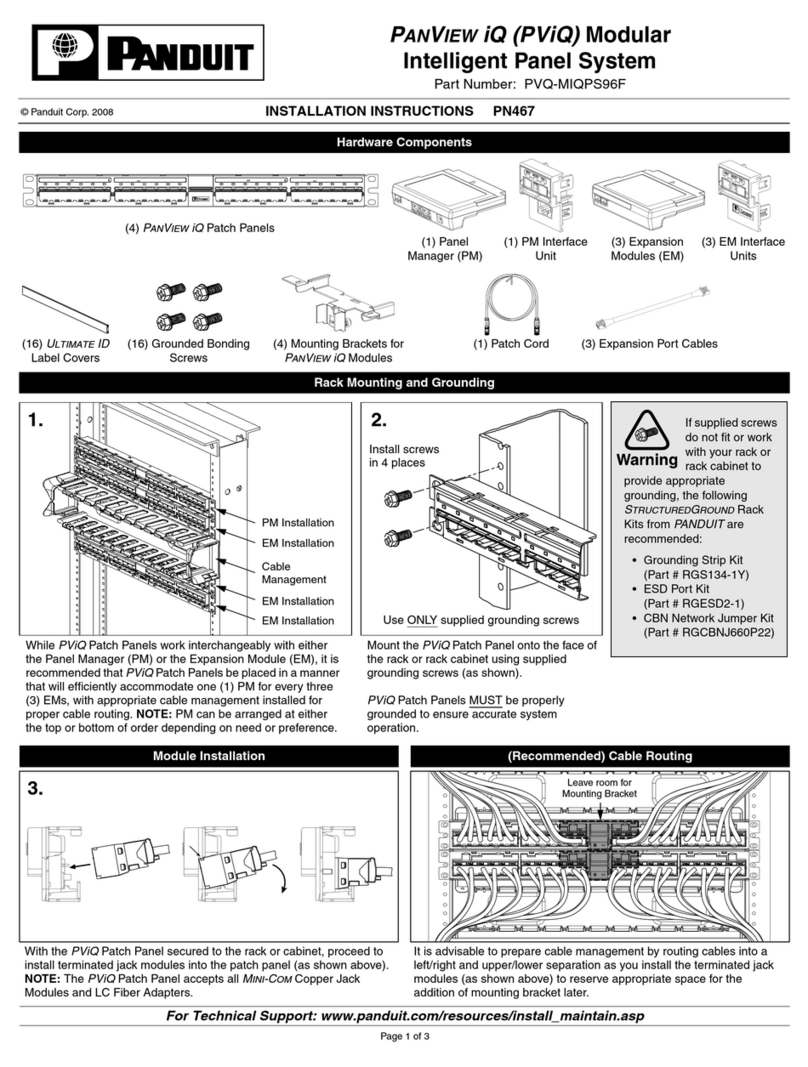
Panduit SmartZone PViQ Use and care manual
Panduit
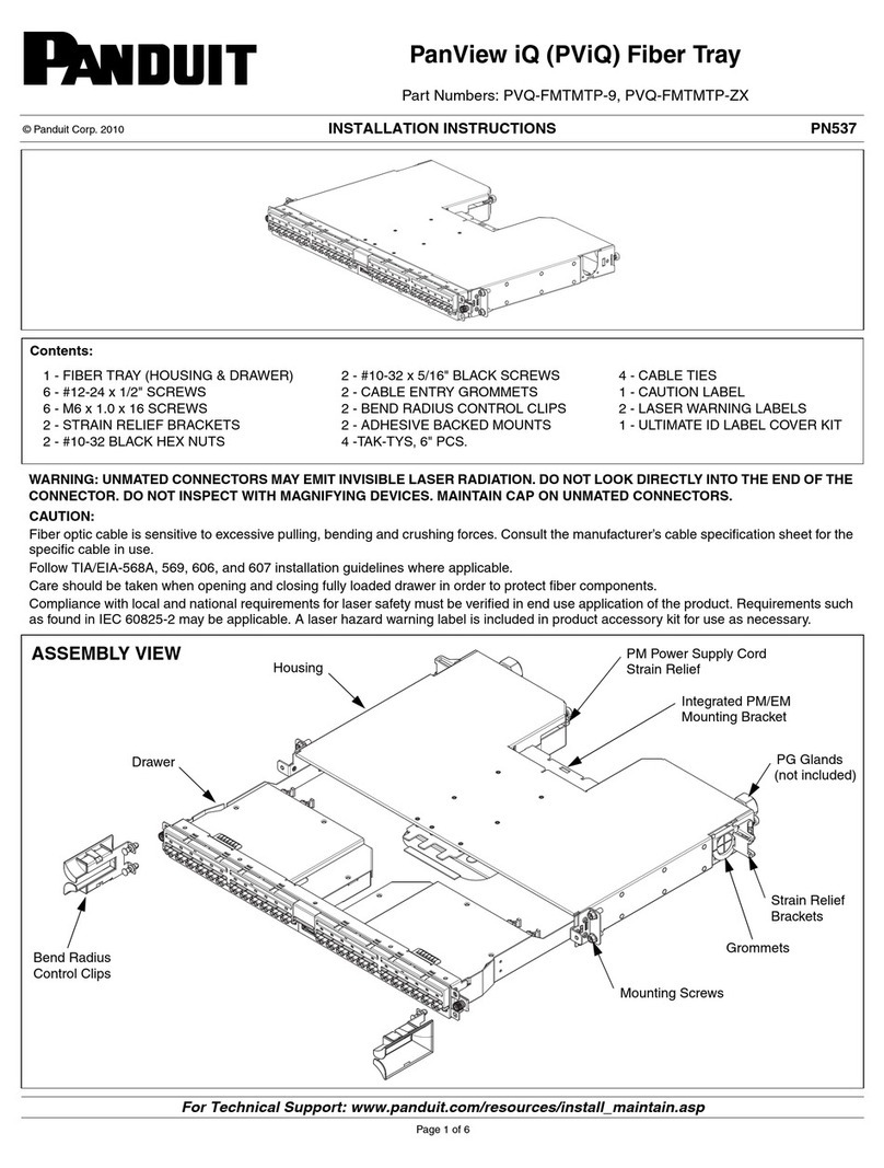
Panduit PANVIEW iQ PVQ-MIQPS96F User manual
Panduit
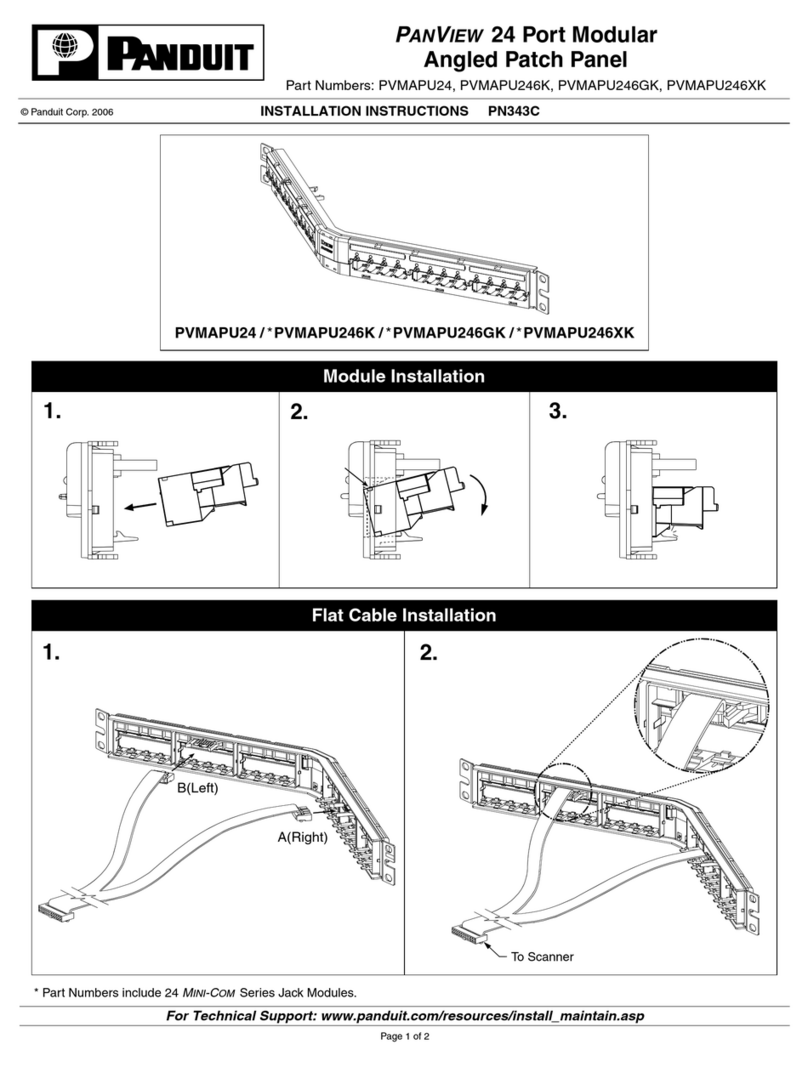
Panduit PVMAPU24 User manual
Panduit
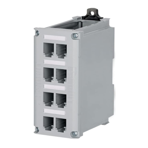
Panduit CDPP8RG-S User manual
Panduit
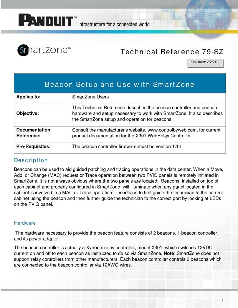
Panduit SmartZone Use and care manual
Panduit
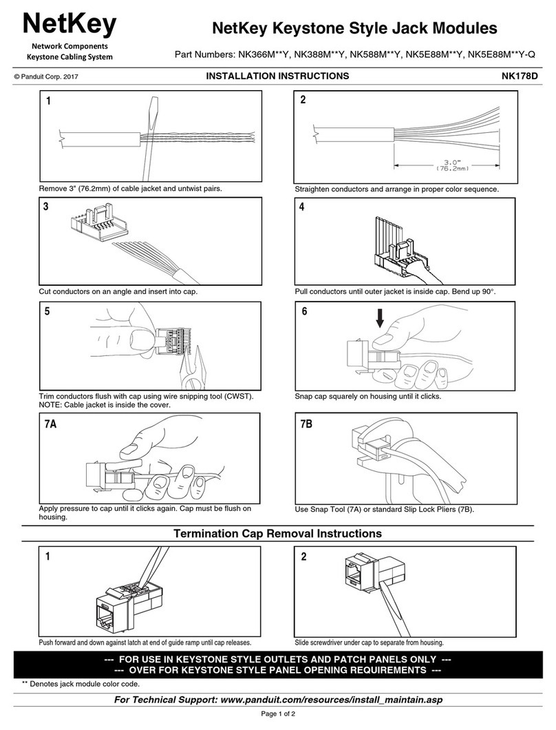
Panduit NetKey NK366M**Y User manual
Popular Network Hardware manuals by other brands

Matrix Switch Corporation
Matrix Switch Corporation MSC-HD161DEL product manual

B&B Electronics
B&B Electronics ZXT9-IO-222R2 product manual

Yudor
Yudor YDS-16 user manual

D-Link
D-Link ShareCenter DNS-320L datasheet

Samsung
Samsung ES1642dc Hardware user manual

Honeywell Home
Honeywell Home LTEM-PV Installation and setup guide
