manuals.online logo
Brands
  1. Home
  2. •
  3. Brands
  4. •
  5. Pantron
  6. •
  7. Amplifier
  8. •
  9. Pantron IMX-N Series User manual

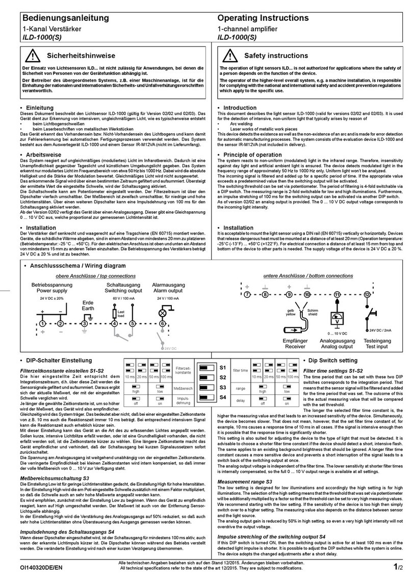
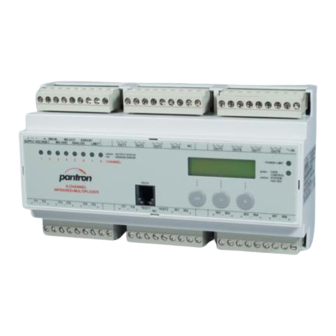
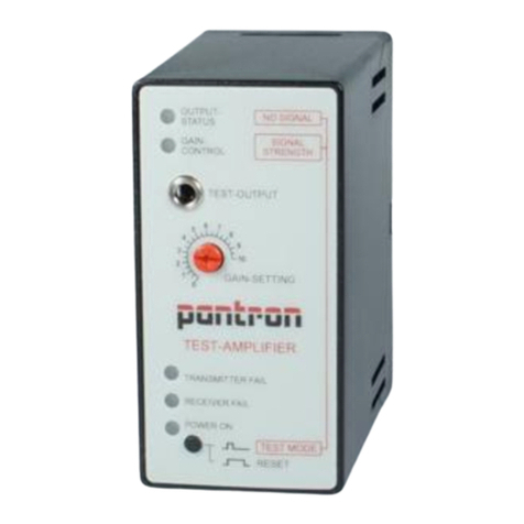
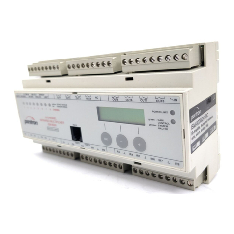
Pantron IMX-N Series User manual

Bedienungsanleitung
2-Kanal Lichtschrankenverstärker
IMX-N...
Operating Instructions
2-channel light barrier amplier
IMX-N...
1/2OI140408DE/EN
Alle technischen Angaben beziehen sich auf den Stand 12/2015. Änderungen bleiben vorbehalten.
All technical specications refer to the state of the art 12/2015. They are subject to modications.
Sicherheitshinweise
Der Einsatz von Infrarot-Verstärkern IMX-N... ist nicht zulässig für Anwendungen,
bei denen die Sicherheit von Personen von der Gerätefunktion abhängig ist.
Der Betreiber des übergeordneten Systems, z.B. einer Maschinenanlage,
ist für die Einhaltung der nationalen und internationalen Sicherheits- und
Unfallverhütungsvorschriften verantwortlich.
•Einleitung
Die Lichtschrankenverstärker werden zur Erkennung von Objekten in Maschinen oder
Produktionsanlagen eingesetzt. Sie bilden in Verbindung mit Infrarotsendern IT... und
Infrarotempfängern IR... (nicht im Lieferumfang) eine leistungsstarke Lichtschranke
und sind einsetzbar in Bereichen mit hoher Reichweite oder Verschmutzung.
•Arbeitsweise
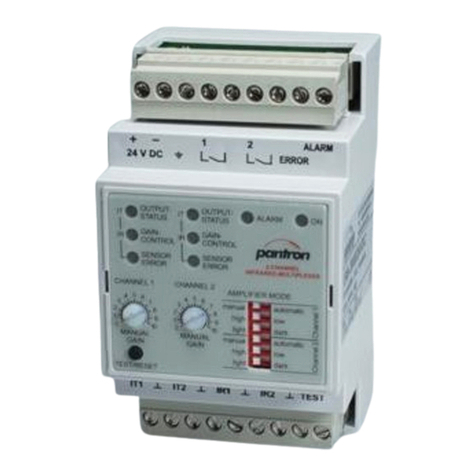
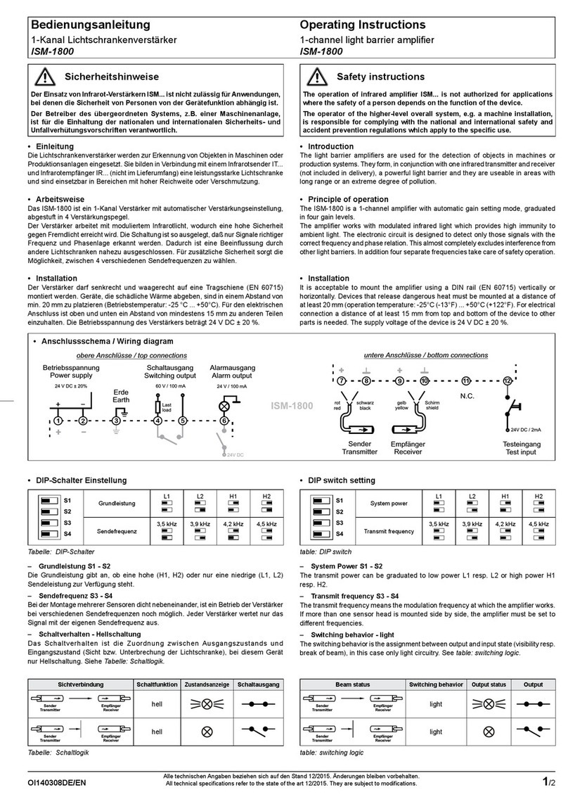
Das IMX-N... ist ein 2-Kanal Multiplex-Verstärker mit manueller Verstärkungseinstellung.
Durch ein Potentiometer wird die Empfindlichkeit je nach Reichweite und
Verschmutzungsgrad für jeden Kanal eingestellt.
Der Verstärker arbeitet mit moduliertem Infrarotlicht, wodurch eine hohe Sicherheit
gegen Fremdlicht erreicht wird. Die Schaltung ist so ausgelegt, daß nur Signale
richtiger Frequenz und Phasenlage erkannt werden. Dadurch ist eine Beeinussung
durch andere Lichtschranken nahezu ausgeschlossen.
•Montage
Die Verstärker sind für eine schnelle Montage und Demontage konzipiert und besitzen
daher einen Steckanschluß. Um eine sichere Funktion zu garantieren und eine
Beschädigung des Gerätes zu vermeiden, immer einen Stecksockel benutzen.
Safety instructions
TheoperationofinfraredamplierIMX-N...isnotauthorizedforapplications
where the safety of a person depends on the function of the device.
The operator of the higher-level overall system, e.g. a machine installation,
is responsible for complying with the national and international safety and
accidentpreventionregulationswhichapplytothespecicuse.
•Introduction
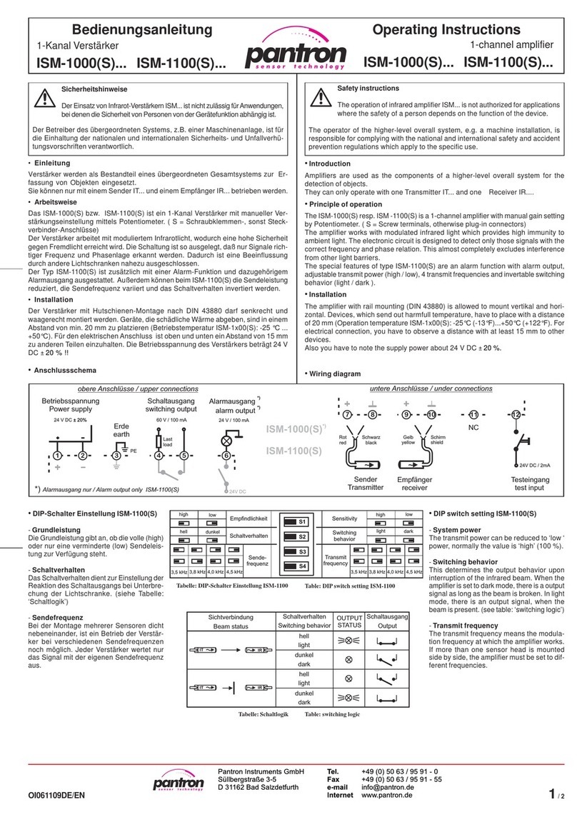
The light barrier ampliers are used for the detection of objects in machines or production
systems. They form, in conjunction with infrared transmitters and receivers (not included
in delivery), a powerful light barrier and they are useable in areas with long range or
an extreme degree of pollution.
•Principle of operation
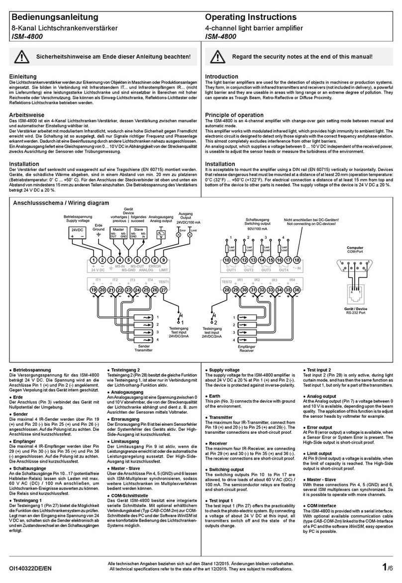
The IMX-N... is a 2-channel multiplex-amplier with manual gain settings. The sensitivity
must be set with a potentiometer according to the mounting range and environmental
inuences for each channel.
The ampliers works with modulated infrared light which provides high immunity to
ambient light. The electronic circuit is designed to detect only those signals with the
correct frequency and phase relation. This almost completely excludes interference
from other light barriers.
•Installation
The device includes a plug for simple installation. As a safe operating procedure and
to avoid damaging the device, use an 11-PIN socket.
•Betriebsspannung
Die Betriebsspannungsangabe ist
in den letzten zwei oder drei Nummern
der Gerätebezeichnung enthalten (siehe
rückseitiges Typenschild).
Bei 24 V DC ein passend dimensioniertes UL
Class 2 Netzteil verwenden.
•Funktionen
Die Funktionen sind mit dem DIP-Schalter auf
der Geräterückseite einzustellen.
– Schaltfunktion
Die Schaltfunktion beschreibt das Verhalten des Schaltausganges beim Unterbrechen
des Infrarotstrahls. Bei Dunkelschaltung erfolgt bei unterbrochener Lichtstrecke ein
Ausgangssignal. In Hellschaltung erfolgt bei freier Lichtstrecke ein Ausgangssignal.
– Grundleistung
Die Grundleistung des Lichtschrankenverstärkers läßt sich unempndlicher schalten.
100 %: Der Verstärker hat seine maximale Empndlichkeit (maximale Reichweite).
20 %: Der Verstärker hat 20 % der maximalen Empndlichkeit zur Verfügung.
– Multiplexgeschwindigkeit
Die Multiplexgeschwindigkeit ist die Geschwindigkeit mit der die Sensoren nacheinander
aktiviert werden.
high: Die Reaktionszeit ist kurz und die Reichweite verringert sich.
low: Die Reaktionszeit ist lang und die Reichweite ist maximal.
•DIP-Schaltereinstellung
1 2 3 4
Schaltfunktion
Kanal 1 Schaltfunktion
Kanal 2 Grundleistung Multiplex-
geschwindigkeit
dunkel ON dunkel ON 100 % ON 16 ms ON
hell OFF hell OFF 20 % OFF 8 ms OFF
Werkseinstellung grau hinterlegt
•Supply voltage
The supply voltage is the last two or three
numbers of the part number. On the bottom
of the amplier is the type plate with the part
number.
24V DC to be provided by a suitably rated UL
Listed Class 2 power supply.
•Functions
The functions are selectable by DIP-switches
on the bottom of the amplier.
– Switching mode
The switching mode determines the output behavior upon interruption of the infrared
beam. When the amplier is set to dark mode, there is an output signal as long as
the beam is broken. In light mode, there is an output signal when the beam is present.
– Transmit power
The transmit power of the light barrier amplier can be switched to less sensitive.
100 %: The amplier has the maximum penetrating power (maximum range).
20 %: The amplier has 20 % of the maximum penetrating power.
– Multiplex speed
The multiplex speed is the speed between activating the sensor heads one after another.
high: The reaction time is short, the range gets shorter.
low: The reaction time is long, the range has the maximum value.
•DIP switch setting
1 2 3 4
switching function
channel 1 switching function
channel 2 transmit
power multiplex
speed
dark ON dark ON 100 % ON 16 ms ON
light OFF light OFF 20 % OFF 8 ms OFF
Factory setting is marked in grey
Typenschild
Stecker
DIP-Schalter
IMX-N34/230VAC
2-ch. multiplexer, manual,
relay, time
Betriebsspannung
zumBeispiel: 230VAC
-16/14-
Type plate
Plug
DIP-switch
Supply voltage
for example: 230VAC
IMX-N34/230VAC
2-ch. multiplexer, manual,
relay, time -16/14-
CH1 CH2
COM
Relais
Relay
Betriebsspannung
Supply voltage
IR1
IR2
Empfänger
Receiver
Gelb/
Yellow
Gelb/
Yellow
Schirm/
Shield
7
Ground
Sender
Transmitter
IT1
IT2
Rot/
Red
Rot/
Red
Schwarz/
Black
•Anschlußschema / Wiring diagram
NPN
(max. 30 VDC)
PNP
7 7
Transistorausgang 2
Transistor output 2
NPN
(max. 30 VDC)
PNP
7 7
Transistorausgang 1
Transistor output 1
nur/only IMX-Nx4... nur/only IMX-Nx3...
2/2
Technische Daten bei 20 °C IMX-N... Technical data at 20 °C (68 °F)
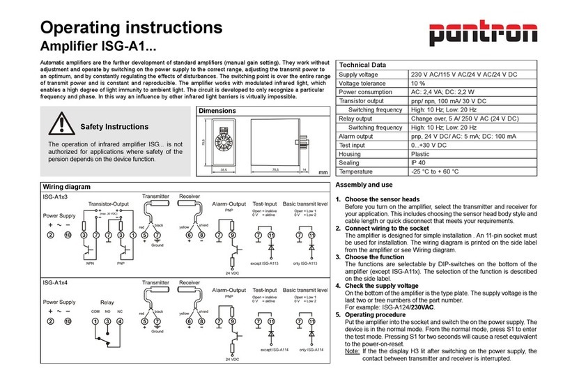
Betriebsspannung ...AC 230 V AC / 115 V AC / 24 V AC / ± 10% / 2,4 VA Supply power ...AC
Betriebsspannung ...DC 24 V DC / ± 20% / 2,0 W Supply power ...DC
Messverfahren moduliertes IR-Licht modulated IR-light Operating basis
Maximale Reichweite (Einweg) Empfänger / Receiver IRL-... Empfänger / Receiver IRH-..., IR-... Maximum range (through beam)
Sender ITL-..., IT-... 10 m (33 ft) 20 m (66 ft) Transmitter ITL-..., IT-...
Sender ITH-..., IT-...HP 15 m (49 ft) 30 m (98 ft) Transmitter ITH-..., IT-...HP
Sender ITA-... 25 m (82 ft) 50 m (165 ft) Transmitter ITA-...
Sendefrequenz 4,0 kHz Transmit frequency
Sendeleistung manuell manual Transmit power
Schaltfunktion bzw. Schaltverhalten hell / dunkel light / dark Switching behavior
Schaltverzögerung nur IMX-N3x... 0 ... 10 s Switching delay only IMX-N3x...
Grundleistung 20 % / 100 % System power manual mode
Multiplexgeschwindigkeit 8 ms / 16 ms Multiplex speed
Relaisausgang nur IMX-Nx4... 2 x Schließer 2 x normally open contact Relay output nur IMX-Nx4...
Strombelastbarkeit maximal 250 V AC (24 V DC) / 5 A Maximum values
Reaktionszeit (TON / TOFF) 8 ms / 8 ms (16 ms / 16 ms)* Reaction time (TON / TOFF)
Transistorausgang nur IMX-Nx3... 2 x pnp / npn Transistor output nur IMX-Nx3...
Schaltwerte maximal 100 mA / 30 V DC Maximum values
Reaktionszeit (TON / TOFF) 8 ms / 8 ms (16 ms / 16 ms)* Reaction time (TON / TOFF)
Alarmausgang ―Alarm output
Testeingang ― Test input
Gehäusewerkstoff Kunststoff Plastic Housing material
Schutzart IP 40 Protection class
Anschluß 11-PIN DIN-Stecksockel 11-PIN DIN socket Mounting
Maximale Kabellänge (Sensor-/Signalanschlüsse) 30 m Maximum cable length (sensor and signal connections)
Betriebstemperatur -25 °C ... + 60 °C (-13 °F ... +140 °F) Operating temperature
Lagertemperatur -40 °C ... + 80 °C (-40 °F ... +176 °F) Storage temperature
Prüfungen Approvals
* Multiplexgeschwindigkeit hoch (niedrig) * Multiplex speed high (low)
•Anzeigen und
Bedienelemente
siehe Bild 1
•Inbetriebnahme
Verstärker in den Sockel stecken
und die Betriebsspannung
einschalten. Die Betriebsanzeige
H1 leuchtet grün. Die Informationen
(unterbrochen oder frei, usw)
werden ermittelt und die Ausgänge
sowie die Anzeigen werden
dementsprechend geschaltet.
Die Anzeige H2 bzw. H4 zeigt den Status des Schaltausgangs an und H3 bzw. H5
die Intensität.
Um eine ordnungsgemäße Funktion des Lichtschrankenverstärkers zu gewährleisten,
muss die Empndlichkeit für jeden Kanal manuell eingestellt werden. Hierzu wird das
Potentiometer P1 vom Linksanschlag nach rechts gedreht, bis die Empndlichkeitsanzeige
H3 konstant leuchtet. Sollte das Potentiometer P1 weiter nach rechts gedreht werden,
so wird die Empndlichkeit verringert und die Verschmutzungsreserve vergrößert
(beschrieben für Kanal 1. Für Kanal 2 Potentiometer P2 und Empndlichkeitsanzeige
H5). Die Arbeitsweise der Schaltausgänge ist in der Tabelle Schaltlogik zu sehen.
Nach erfolgter Einstellung ist die Empndlichkeitsanzeige H3 oder H5 weiterhin ein
Indikator für die ordnungsgemäße Funktion des Verstärkers. Sollte nach längerer
Betriebszeit ein Sensor langsam verschmutzen, beginnt H3 bzw. H5 zu ackern und
erlöscht bei weiterer Verschmutzung. Um wieder einen optimalen Betrieb des Gerätes
herzustellen, muss entweder die Empndlichkeit erhöht oder die Verschmutzung
beseitigt werden. Mit den Potentiometer P3 und P4 für Kanal 1 bzw. P5 und P6 für
Kanal 2 (nur IMX-N3...) kann die Ein- und Ausschaltverzögerung zwischen 0...10 s
eingestellt werden.
i
WenndieEmpndlichkeitsanzeigeH3oderH5nichtleuchtet,istdieSicht-
verbindung zwischen Sender und Empfänger unterbrochen (verschmutzt
oder falsch justiert) oder der Abstand zwischen den Sensoren ist zu groß.
•Display contents and
operating elements
see picture 1
•Operating procedure
Put the amplifier into the
socket and switch on the
power supply. The power
on indicator H1 lights green.
The information (interrupt or
clearance, etc.) is evaluated
and the state of the displays
and outputs are shown. The
displays H2 resp. H4 indicates the state of the outputs and H3 resp. H5
indicates the state of the sensitivity.
To guarantee the regular operation of the infrared amplier, the sensitivity must
be adjusted manually. For this, turn the potentiometer P1 from the left side
to the right side until the green sensitivity indicator H3 is lit constantly. As the
potentiometer P1 is adjusted to the right side, the amplier will become less
sensitive (descriped for channel 1. For channel 2 use potentiometer P2 and
sensitivity indicator H5). For description of how the switching output works, see
the table Switching logic.
After adjustment, the sensitivity display H3 and H5 serves as an indicator
for the correct adjustment of the amplier. After many work days the sensor
heads polluted slowly. The sensitivity display H3 or H5 will begin to ash and
eventually go out if the sensor heads become contaminated. For optimal
working conditions, the sensitivity must be increased or sensor heads must be
cleaned. The switching ON and OFF delay is adjustable between 0...10 s using
potentiometers P3 and P4 for channel 1 resp. P5 and P6 for channel 2 (only
IMX-N3...).
i
IfthesensitivitydisplayH3orH5isnotlit,thecontactbetweenthe
transmitter and receiver is interrupted, polluted, adjusted incorrectly,
or the distance between the sensor heads is too far.
GAIN1-CONTROL
OUTPUT 1-STATUS
OUTPUT 2-STATUS
GAIN2-CONTROL
GAIN1 t-OFF
(0-10 sec.)
TIMER 1
TIMER 2
t-ON
t-ON
t-OFF
GAIN2
POWER ON
2-CHANNEL
INFRARED-MULTIPLEXER
Einschaltverzögerung 1
P3-Potentiometer
Ausschaltverzögerung 1
P4-Potentiometer
Einschaltverzögerung 2
P5-Potentiometer
Ausschaltverzögerung 2
P6-Potentiometer
Betrieb
H1-LED grün
Empfindlichkeit 1
H3-LED grün
Schaltzustand 1
H2-LED gelb
Schaltzustand 2
H4-LED gelb
Empfindlichkeit 2
LED grünH5 -
Empfindlichkeit 1
P1-Potentiometer
Empfindlichkeit 2
PotentiometerP2 -
nur IMX-N3x
Bild 1
GAIN1-CONTROL
OUTPUT 1-STATUS
OUTPUT 2-STATUS
GAIN2-CONTROL
GAIN1 t-OFF
(0-10 sec.)
TIMER 1
TIMER 2
t-ON
t-ON
t-OFF
GAIN2
POWER ON
2-CHANNEL
INFRARED-MULTIPLEXER
Switching-on delay 1
P3-Potentiometer
Switching-off delay 1
P4-Potentiometer
Switching-on delay 2
P5-Potentiometer
Switching-off delay 2
P6-Potentiometer
Power
H1-LED green
Intensity 1
greenH3-LED
Output status 1
H2-LED yellow
Output status 2
H4-LED gelb
Intensity 2
LED greenH5 -
Gain setting 1
P1-Potentiometer
Gain setting 2
PotentiometerP2 -
only IMX-N3x
picture 1
•Schaltlogik / Switching logic
Sichtverbindung
Beam status
Schalt-
funktion
Switching
mode
Zustandsan-
zeige
Switching
indicator
Relais-
ausgang
Relay
output
Transistor-
ausgang
Transistor
output
Sender
Transmitter
Empfänger
Receiver
hell
light 0 V
dunkel
dark 24 V DC
Sender
Transmitter
Empfänger
Receiver
hell
light 24 V DC
dunkel
dark 0 V
•Maßzeichnungen / Dimensions (in mm)
40
76,5
Pantron Instruments GmbH
Süllbergstraße 3-5
D-31162 Bad Salzdetfurth
Tel. +49 (0) 5063 / 9591-0
Fax +49 (0) 5063 / 9591-55
E-mail [email protected]
Internet www.pantron.de

This manual suits for next models

2

Other Pantron Amplifier manuals

Pantron ISM-1500 User manual

Pantron

Pantron ISM-1500 User manual

Pantron ISM-8000 Series User manual

Pantron

Pantron ISM-8000 Series User manual

Pantron ISM-4000 User manual

Pantron

Pantron ISM-4000 User manual

Pantron ISG-N1 Series User manual

Pantron

Pantron ISG-N1 Series User manual

Pantron ISG-A104 Series User manual

Pantron

Pantron ISG-A104 Series User manual

Pantron ISG-A1 Series User manual

Pantron

Pantron ISG-A1 Series User manual

Pantron ISG-A101 User manual

Pantron

Pantron ISG-A101 User manual

Pantron ISM-1200 User manual

Pantron

Pantron ISM-1200 User manual

Pantron ILD-1000(S) User manual

Pantron

Pantron ILD-1000(S) User manual

Pantron ISM-1220S User manual

Pantron

Pantron ISM-1220S User manual

Pantron ISM-4800 User manual

Pantron

Pantron ISM-4800 User manual

Pantron ISM-8800 User manual

Pantron

Pantron ISM-8800 User manual

Pantron ISM-2000 User manual

Pantron

Pantron ISM-2000 User manual

Pantron ISG-N Series User manual

Pantron

Pantron ISG-N Series User manual

Pantron ISM-1800 User manual

Pantron

Pantron ISM-1800 User manual

Pantron ISG-N124M User manual

Pantron

Pantron ISG-N124M User manual

Pantron ISM-1000 Series User manual

Pantron

Pantron ISM-1000 Series User manual

Pantron ISM-1000 User manual

Pantron

Pantron ISM-1000 User manual

Pantron ISG-A1 Series User manual

Pantron

Pantron ISG-A1 Series User manual

Popular Amplifier manuals by other brands

Optoma nu force MCA30 user manual

Optoma

Optoma nu force MCA30 user manual

Kanto YARO2 user manual

Kanto

Kanto YARO2 user manual

Directed Electronics Precision Power A1200/4 owner's manual

Directed Electronics

Directed Electronics Precision Power A1200/4 owner's manual

SONNETEER BRONTE instruction manual

SONNETEER

SONNETEER BRONTE instruction manual

Boss Audio Systems EQ600 user manual

Boss Audio Systems

Boss Audio Systems EQ600 user manual

Xtant 1.1I owner's manual

Xtant

Xtant 1.1I owner's manual

Panasonic MINAS-BL GU series operating instructions

Panasonic

Panasonic MINAS-BL GU series operating instructions

RMS RMS120RH Operation manual

RMS

RMS RMS120RH Operation manual

Bogen X-C35B Addendum manual

Bogen

Bogen X-C35B Addendum manual

Measurement Computing 101 operating manual

Measurement Computing

Measurement Computing 101 operating manual

Hertz PowerSports HMP 1D user manual

Hertz

Hertz PowerSports HMP 1D user manual

Traynor YGL1 Service manual

Traynor

Traynor YGL1 Service manual

Sonic Farm Silk Road user manual

Sonic Farm

Sonic Farm Silk Road user manual

DaytonAudio DTA-100LF user manual

DaytonAudio

DaytonAudio DTA-100LF user manual

McIntosh C8 - SCHEMATICS owner's manual

McIntosh

McIntosh C8 - SCHEMATICS owner's manual

Haas AD0263 Replacement

Haas

Haas AD0263 Replacement

SPHINX PROJECT EIGHTEEN user manual

SPHINX

SPHINX PROJECT EIGHTEEN user manual

Potter SCA manual

Potter

Potter SCA manual

manuals.online logo
manuals.online logoBrands
  • About & Mission
  • Contact us
  • Privacy Policy
  • Terms and Conditions

Copyright 2025 Manuals.Online. All Rights Reserved.