manuals.online logo
Brands
  1. Home
  2. •
  3. Brands
  4. •
  5. Pantron
  6. •
  7. Amplifier
  8. •
  9. Pantron ISM-1220S User manual

Pantron ISM-1220S User manual

Bedienungsanleitung Operating Instructions
1-KanalVerstärker
ISM-1220(S)... 1-channelamplifier
ISM-1220(S)...
Seite 1/ 2 Page 1/ 2
Pantron Instruments GmbH
Süllbergstraße 3-5
D 31162 Bad Salzdetfurth
Tel.
Fax
e-mail
Internet
++49 (0) 50 63 / 95 91 - 0
++49 (0) 50 63 / 95 91 - 55
[email protected]
www.pantron.de
Sicherheitshinweise
Der Einsatz von Infrarot-Verstärkern ISM... ist nicht zulässig für Anwendun-
gen, bei denen die Sicherheit von Personen von der Gerätefunktion abhängt.
Der Betreiber des übergeordneten Systems, z.B. einer Maschinenanlage, ist für
die Einhaltung der nationalen und internationalen Sicherheits- und Unfallverhü-
tungsvorschriften verantwortlich.
Safety instructions
TheoperationofinfraredamplifierISM...isnotauthorizedforapplications
where the safety of a person depends on the function of the device.
The operator of the higher-level overall system, e.g. a machine installation, is
responsible for complying with the national and international safety and accident
prevention regulations which apply to the specific use.
•Einleitung
Verstärker werden als Bestandteil eines übergeordneten Gesamtsystems zur Er-
fassung von Objekten eingesetzt.
Sie können nur mit einem Sender IT... und einem Empfänger IR... betrieben werden.
•Arbeitsweise
Das ISM-1220S ist ein 1-Kanal Verstärker mit umschaltbarer Verstärkungseinstel-
lung zwischen Manuell und Automatik (Potentiometer / Prozessor) per DIP-Schalter.
Der Verstärker arbeitet mit moduliertem Infrarotlicht, wodurch eine hohe Sicherheit
gegen Fremdlicht erreicht wird. Die Schaltung ist so ausgelegt, daß nur Signale
richtiger Frequenz und Phasenlage erkannt werden. Dadurch ist eine Beeinflussung
durch andere Lichtschranken nahezu ausgeschlossen.
Der Relaisausgang schaltet wahlweise zeitverzögert ‘delay’ (zwischen 0...10 s
einstellbar) oder impulsartig ‘pulse’ mit einstellbarer Impulsdauer zwischen 0...10 s.
•Installation
Der Verstärker mit Hutschienen-Montage nach DIN 43880 darf senkrecht und
waagerecht montiert werden. Geräte, die eine Wärme von > 30° C abgeben, sind in
einem Abstand von min. 20 mm zu platzieren (Betriebstemperatur: -25 °C ...
+50°C). Für den elektrischen Anschluss über die Schraubklemmen ist oben und
unten ein Abstand von 15 mm zu anderen Teilen einzuhalten.
Die Betriebsspannung des Verstärkers auf dem Typenaufkleber ist zu beachten!!
•Anschlussschema
•Introduction
Amplifiers are used as the components of a higher-level overall system for the
detection of objects.
They can only operate with one Transmitter IT... and one Receiver IR....
•Principle of operation
The ISM-1220S is a 1-channel amplifier with change-over gain setting mode between
manual and automatic (Potentiometer / Processor) by DIP switch.
The amplifier works with modulated infrared light which provides high immunity to
ambient light. The electronic circuit is designed to detect only those signals with the
correct frequency and phase relation. This almost completely excludes interference
from other light barriers.
The relay output switches either delayed with adjustable time between 0...10 s or
pulsed with adjustable period between 0...10 s.
•Installation
The amplifier with rail mounting (DIN 43880) is allowed to mount vertikal and
horizontal. Devices, which send out temperature > 30° C (86° F), have to place with
a distance of 20 mm (Operation temperature: -25°C (-13°F)...+50°C (+122°F). For
electrical connection with the terminals, you have to observe a distance with at
least 15 mm to other devices.
Also you have to note the supply power on the type plate!!
•Wiring diagram
untere Anschlüsse / under connectionsobere Anschlüsse / upper connections
IT IR
Testeingang
Test input
Errorausgang
Error output
14 15
60V / 100 mA
16 17
ALARM ERROR
60V / 100 mA
Alarmausgang
Alarm output
18
Sender
Transmitter
rot
red
schwarz
black
Empfänger
Receiver
gelb
yellow
Schirm
shield
131211
~~
TEST
10
NO COM
NC
789
Relais
Relay
5
PE
Erde
Earth
6
4
3
Betriebsspannung
Power supply
2
230 V AC ± 10%
2
~~
~~
Betriebsart
Schaltverhalten
Sendefrequenz
Manuell Automatik
dunkel
hell
manual
high low
dark
4,3 kHz
3,7 kHz
light
automatic
Operation mode
Sensitivity
Switching
behavior
Transmit
frequency
4,3 kHz
3,7 kHz
Empfindlichkeit
high low
S1
S2
S3
S4
S5
S6
Reaktionsart
Schaltzeitpunkt
pulse
delay
on-delay
off-delay
pulse
delay
on-delay
off-delay
Switching
reaction
Release time
Tabelle: DIP-Schalter Einstellung Table: DIP switch setting
•DIP-Schalter Einstellung S1 - S6
- Betriebsart
In der Betriebsart ‘Manuell’ stellt der An-
wender über ein Potentiometer die Sende-
leistung auf seine Anwendung ein. Bei ‘Au-
tomatik’ erfolgt eine automatische Einstel-
lung und Regelung der Leistung.
- Empfindlichkeit
Die Empfindlichkeit kann bei Bedarf redu-
ziert werden (low). Die max. Empfindlich-
keit wird in der Einstellung ‘high’ erreicht.
- Schaltverhalten
Das Schaltverhalten dient der Reaktions-Ein-
stellung des Schaltausgangs bei Unterbrechung
der Lichtschranke. (siehe Tabelle: ‘Schaltlogik’)
- Sendefrequenz
Bei Montage mehrerer Sensoren dicht nebenein-
ander, ist ein Betrieb der Verstärker bei ver-
schiedenen Sendefrequenzen noch möglich. Je-
der Verstärker wertet nur das Signal mit der ei-
genen Frequenz aus.
- Reaktionsart
Zur Auswahl stehen normale (verzögerte) oder
impulsartige Reaktion des Relais-Ausgangs.
- Schaltzeitpunkt
Der Schalter legt fest, ob zu Beginn oder zum
Ende der Unterbrechung eine Verzögerung oder
ein Impuls erfolgen soll.
•DIP switch setting S1 - S6
- Operation mode
You can choose the operation mode bet-
ween ‘manual’ (the user adjusts the required
transmit power with a potentiometer) and
‘automatic’(transmit power is setting by the
processor-controlled amplifier).
- Sensitivity
Thesensitivitycanbereducedto‘low‘mode,
normally the sensitivity is ‘high’ (100 %).
- Switching behavior
This determines the output behavior upon
interruption of the infrared beam. When the
amplifier is set to dark mode, there is a output
signal as long as the beam is broken. In light
mode, there is an output signal, when the beam
is present. (see table: ‘switching logic’)
- Transmit frequency
The transmit frequency means the modulation
frequency at which the amplifier works. If more
than one sensor head is mounted side by side,
the amplifier must be set to different frequen-
cies.
- Switching reaction
You can choose between delayed or pulsed
reaction of the relay output.
- Release time
This switch determines the point of time when
the delay or pulse starts, either at the beginning
or end of beam interruption.
hell
light
Relaisausgang
Relay output
OUTPUT
STATUS
Schaltverhalten
Switching behavior
IT IR
IT IR
hell
light
dunkel
dark
dunkel
dark
Sichtverbindung
Beam status
NO COM
NC
7 8 9
NO COM
NC
7 8 9
NO COM
NC
7 8 9
NO COM
NC
7 8 9
Tabelle: Schaltlogik Table: switchinglogic
Bedienungsanleitung Operating Instructions
1-KanalVerstärker
ISM-1220(S)... 1-channelamplifier
ISM-1220(S)...
All technical specifications refer to
the state of the art 08/2004.
They are subject to modifications.
AlletechnischenAngabenbeziehen
sich auf den Stand 08/2004.
Änderungenbleibenvorbehalten.
Seite 2/ 2 Page 2/ 2
Pantron Instruments GmbH
Süllbergstraße 3-5
D 31162 Bad Salzdetfurth
Tel.
Fax
e-mail
Internet
++49 (0) 50 63 / 95 91 - 0
++49 (0) 50 63 / 95 91 - 55
[email protected]
www.pantron.de
Technische Daten
(bei 20 °C U = U )
bN
Betriebsspannung
Messverfahren
max. Reichweite (Einweg)
Sensoren ITL... + IRL...
Sensoren ITH... + IRL...
Sensoren ITL... + IRH...
Sensoren ITH... + IRH...
Sendefrequenz [kHz]
Sendeleistung
Schaltfunktion bzw. Schaltverhalten
Grundleistung
Schaltverzögerung / Impulsbreite
Schaltausgang
Schaltwerte
Reaktionszeit
Alarm-/ Errorausgang (kurzschlussfest)
Analogausgang
Testeingang
Gehäusewerkstoff
Schutzart
Betriebstemperatur
Supply power
Operating basis
max. range
Sensor heads ITL... + IRL...
Sensor heads ITH... + IRL...
Sensor heads ITL... + IRH...
Sensor heads ITH... + IRH...
Transmit frequency [kHz]
Transmit power
Switching behavior
System power
Switching delay / impulse period
Switching output
values (max.)
reaction time
Alarm / Error output (short-circuit proof)
Analog output
Housing material
Test input
Protection class
Operation temperature
Technical data
(at 20°C, V = V )
SN
230V--115V--24VAC/± 10% / 4,8 VA
moduliertes IR-Licht modulated IR-light
08 m (26 ft)
10 m (33 ft)
15 m (49 ft)
20 m (66 ft)
3,7 / 4,3
manuell / automatisch manual / automatic
hell / dunkel light / dark
high / low
0-10s
Change-over relay
5 A / 230 V AC (24 V DC)
20 Hz (Low) / 11 Hz (High)
Schließer 60 V AC (DC) / 100 mA
---
Aktiv LOW (L= 0 ...5VDC H=15...30VDC)
NORYL RAL 7035 (grau | grey)
IP 20
ISM-1220S
1 Wechsler (mech. Relais)
Gehäuse-Abmessungen Housing measurementssiehe Maßzeichnungen see dimensions
-25 °C ... +50 °C (-13 °F...+122 °F)
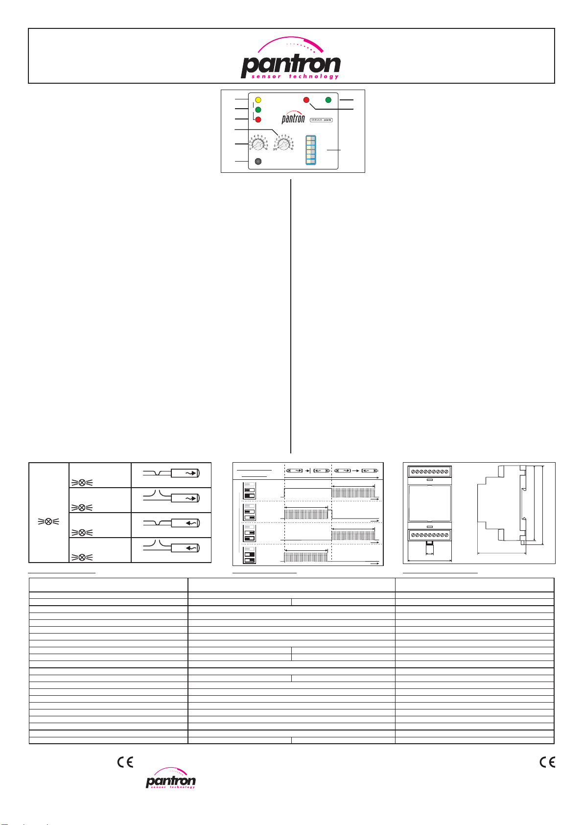
•Anzeigen und Bedienelemente
H1: Schaltzustandsanzeige / Fehleranzeige Sender
H2: Empfindlichkeitsanzeige / Fehleranzeige Empfän-
ger
H3: Sensor-Fehleranzeige
H4: Alarmanzeige
H5: Betriebsanzeige
P1: Empfindlichkeitseinsteller für Manuell-Betrieb
P2: Einsteller für Verzögerungszeit / Impulsdauer
S1 - S6: DIP-Schalter für Funktionseinstellungen
S7: Test / Reset-Taster
•Display content
H1: Switching indicator / Transmitter error
display
H2: Sensitivity display / Receiver error display
H3: Sensor Error display
H4: Alarm display
H5: Power ON display
P1: Manual Gain setting
P2: Delay and pulse period setting
S1 - S6: DIP-switch for operation settings
S7: Test / Reset-Taster
H1
H2
H3
H5
P1
S7
S1-S6
MANUAL
GAIN
IT
IR
OUTPUT-
STATUS
GAIN-
CONTROL
SENSOR
ERROR
ALARM ON
TEST/RESET
high
manual
f1
delay
off-delay
low
automatic
f2
pulse
on-delay
darklight
AMPLIFIER MODE
DELAY/
PULSE
IR-AMPLIFIER
H4
P2
•Inbetriebnahme
Vor Inbetriebnahme DIP-Schalter S1 - S6 am Gerät passend einstellen. Sensoren
aufeinander ausrichten. Nach Anlegen der Betriebsspannung und automatischem
Reset, stellt sich in der Betriebsart ‘Automatik’ die Sendeleistung selbstständig ein.
Bei fehlerfreiem Betrieb leuchtet H2 auf (Automatik aktiv). Gleichzeitig leuchtet in
Hellschaltung H1. In der Betriebsart ‘Manuell’ muss der Anwender die Sendeleistung
mit P1 auf die erforderliche Höhe bringen, sodass bei Sichtverbindung H2 leuchtet.
In Hellschaltung leuchtet auch hier gleichzeitig H1. (siehe Tabelle ‘Schaltlogik’)
•Schaltreaktionsart delay / pulse
Die Funktionsweise bei Hellschaltung erklärt Tabelle ‘Logik delay / pulse’.
•- Reset -
Nach Anlegen der Betriebsspannung oder Drücken von S7 führt das Gerät einen
Reset durch. Er beinhaltet einen Lampentest. Alle Anzeigen erlischen und leuchten
danach kurz auf. Zusätzlich findet im Automatik-Betrieb eine automatische Neu-
regelung der Sendeleistung vom Maximal- auf den erforderlichen Wert statt.
•- Alarm - und Alarmausgang
Der Alarmzustand tritt ein, wenn die Sendeleistung im Manuell-Betrieb nicht ausrei-
chend ist, oder im Automatik-Betrieb der Prozessor nicht mehr nachregeln kann.
Ursache ist z. B. eine Verschlechterung der Sicht, eine zu große Distanz oder
Dejustage der Sensoren. Nach Beseitigung des Fehlers erlischt die Anzeige.
•- Test -
Durch kurzes Drücken von S7 wird die Streckenqualität durch Blinken von H2 (1x
- schlecht bis 10x - sehr gut) angezeigt. Ohne Sichtverbindung blinkt lediglich H3.
• Testeingang
Legt man an den Testeingang an Masse, so schaltet der Sender ab. Damit kann die
Funktion des Systems überprüft werden.
•- Sensor-Error - und Errorausgang
Mit der Sensor Error-Funktion überwacht das Gerät den elektrischen Zustand der
Sensoren auf Kurzschluss und Unterbrechung. Tritt ein Fehler auf, so meldet dies
das Gerät durch H3 und den Errorausgang. Schnelles Blinken bedeutet Kurzschluss
undlangsamesBlinkenbedeutetUnterbrechung(sieheTabelle:‘LogikSensorError’).
•Operating procedure
Before operating procedure you have to choose the DIP switch setting S1 - S6 for
your application. Sensor heads adjusts one on top of the other. After switch on the
power supply and automatic Reset, the transmit power will be turned to the
optimum (Automatic mode) . When there is no error LED H2 lights (automatic
active) and H1 lights (in light switching mode). In the Manual mode you have to
adjust the transmit power with P1 until H2 signals sufficient power. In light switching
mode H1 lights too. (see also table ‘Switching logic’)
•Switching reaction delay / pulse
This function describes table ‘Logic delay / pulse’ for switching behavior ‘light’.
•- Reset -
After connecting the device with power supply or pressing of button S7 for longer
time a Reset will done. This means a test of all displays. All LEDs lights down and
up for a short time. Additionally in Automatic mode a new adjustment of the
transmit power starts from maximum to the nominal value.
•- Alarm - and Alarm output
Alarm is active, when the transmit power is not sufficient in the Manual mode or the
automatic adjustment is interrupted. The cause can be e. g. deterioration of the
beam, too large distance or misadjustment of sensor heads. Is the cause removed,
the alarm is no longer active.
•- Test -
Short-time pressing of button S7 results flashes between 1 and 10 times of H2
(proportional to the received signal). If there is no signal, then H3 flashes only.
•Test input
By connecting the test input to GND, the transmitter beam switches off. With this
feature you can test the system.
•Sensor Error - and Error output
This function controls the electrical state of the sensor heads. If there is a error
(short-circuit or too high resistance resp. disconnection) H3 lights up. Additionally
H1 (transmitter error) or / and H2 (receiver error) flashes slowly (high resistance)
or fast (short-circuit). See for this table ‘Logic Sensor Error’.
SENSOR
ERROR
OUTPUT-STATUS
OUTPUT-STATUS
GAIN-CONTROL
GAIN-CONTROL
IT
IT
H3
H1
H1
H2
H2
Kurzschluss | short-circuit
hochohmig | high resistance
Kurzschluss | short-circuit
hochohmig | high resistance
IR
IR
schnelles Blinken
fast flashes
langsames Blinken
slowly flashes
schnelles Blinken
fast flashes
langsames Blinken
slowly flashes
Angaben in mm | values in mm
58
89,6
95
Maßzeichnungen| DimensionsLogik | Logic Sensor Error
52,8
9,5
Dt= 0...10 s
t
t
Dt= 0...10 s
t
Dt= 0...10 s
t
Dt= 0...10 s
t
IT IR IT IR
Eingangszustand
Beam status
S6
Relais-Ausgang|relayoutput
S5
COM - NC
COM - NO
COM - NC
COM - NO
COM - NC
COM - NO
COM - NC
COM - NO
S6
S5
S6
S5
S6
S5
Logik | Logic delay / pulse

This manual suits for next models

1

Other Pantron Amplifier manuals

Pantron ISG-A101 User manual

Pantron

Pantron ISG-A101 User manual

Pantron ISM-4800 User manual

Pantron

Pantron ISM-4800 User manual

Pantron ISG-N Series User manual

Pantron

Pantron ISG-N Series User manual

Pantron ISM-8000 Series User manual

Pantron

Pantron ISM-8000 Series User manual

Pantron ISG-A1 Series User manual

Pantron

Pantron ISG-A1 Series User manual

Pantron ISG-A104 Series User manual

Pantron

Pantron ISG-A104 Series User manual

Pantron ISG-N124M User manual

Pantron

Pantron ISG-N124M User manual

Pantron ISM-1200 User manual

Pantron

Pantron ISM-1200 User manual

Pantron ISM-1000 User manual

Pantron

Pantron ISM-1000 User manual

Pantron IMX-N Series User manual

Pantron

Pantron IMX-N Series User manual

Pantron ISM-1500 User manual

Pantron

Pantron ISM-1500 User manual

Pantron ILD-1000(S) User manual

Pantron

Pantron ILD-1000(S) User manual

Pantron ISM-8800 User manual

Pantron

Pantron ISM-8800 User manual

Pantron ISM-1800 User manual

Pantron

Pantron ISM-1800 User manual

Pantron ISM-1000 Series User manual

Pantron

Pantron ISM-1000 Series User manual

Pantron ISG-N1 Series User manual

Pantron

Pantron ISG-N1 Series User manual

Pantron ISM-2000 User manual

Pantron

Pantron ISM-2000 User manual

Pantron ISM-4000 User manual

Pantron

Pantron ISM-4000 User manual

Pantron ISG-A1 Series User manual

Pantron

Pantron ISG-A1 Series User manual

Popular Amplifier manuals by other brands

Megger VAX020 user manual

Megger

Megger VAX020 user manual

Radio Systems DDA 1x4SH manual

Radio Systems

Radio Systems DDA 1x4SH manual

Alpine MRA-D550 - V12 Amplifier owner's manual

Alpine

Alpine MRA-D550 - V12 Amplifier owner's manual

HPA B 300 owner's manual

HPA

HPA B 300 owner's manual

Miteq LN Series manual

Miteq

Miteq LN Series manual

Harman Kardon CITATION 7.1 Schematic diagrams

Harman Kardon

Harman Kardon CITATION 7.1 Schematic diagrams

Elan Z Series Z-660 Brochure & specs

Elan

Elan Z Series Z-660 Brochure & specs

Hogtunes NCA 450-RM installation manual

Hogtunes

Hogtunes NCA 450-RM installation manual

Crown DSi 2000 Architectural & engineering specifications

Crown

Crown DSi 2000 Architectural & engineering specifications

Technics SU-V8 Service manual

Technics

Technics SU-V8 Service manual

Xtant 603X Installer's reference guide

Xtant

Xtant 603X Installer's reference guide

Link electronics DigiFlex 1153 Specification sheet

Link electronics

Link electronics DigiFlex 1153 Specification sheet

Roland KC-350 owner's manual

Roland

Roland KC-350 owner's manual

Kenwood KAC-6403 instruction manual

Kenwood

Kenwood KAC-6403 instruction manual

Goodmans GHC31PLL user guide

Goodmans

Goodmans GHC31PLL user guide

Russound VM1 Video Matrix brochure

Russound

Russound VM1 Video Matrix brochure

Hifonics Brutus BX1500D user guide

Hifonics

Hifonics Brutus BX1500D user guide

Onkyo A-807 instruction manual

Onkyo

Onkyo A-807 instruction manual

manuals.online logo
manuals.online logoBrands
  • About & Mission
  • Contact us
  • Privacy Policy
  • Terms and Conditions

Copyright 2025 Manuals.Online. All Rights Reserved.