manuals.online logo
Brands
  1. Home
  2. •
  3. Brands
  4. •
  5. Pantron
  6. •
  7. Amplifier
  8. •
  9. Pantron ISM-1000 Series User manual

Pantron ISM-1000 Series User manual

Bedienungsanleitung Operating Instructions
1-Kanal Verstärker
ISM-1000(S)... ISM-1100(S)... 1-channel amplifier
ISM-1000(S)... ISM-1100(S)...
1/ 2
OI061109DE/EN
Sicherheitshinweise
DerEinsatzvonInfrarot-VerstärkernISM...istnichtzulässigfürAnwendungen,
beidenendieSicherheitvonPersonenvon der Gerätefunktion abhängig ist.
Der Betreiber des übergeordneten Systems, z.B. einer Maschinenanlage, ist für
die Einhaltung der nationalen und internationalen Sicherheits- und Unfallverhü-
tungsvorschriften verantwortlich.
Safety instructions
Theoperationofinfraredamplifier ISM... is not authorized for applications
where the safety of a person depends on the function of the device.
The operator of the higher-level overall system, e.g. a machine installation, is
responsible for complying with the national and international safety and accident
prevention regulations which apply to the specific use.
•Einleitung
Verstärker werden als Bestandteil eines übergeordneten Gesamtsystems zur Er-
fassung von Objekten eingesetzt.
Sie können nur mit einem Sender IT... und einem Empfänger IR... betrieben werden.
•Arbeitsweise
Das ISM-1000(S) bzw. ISM-1100(S) ist ein 1-Kanal Verstärker mit manueller Ver-
stärkungseinstellung mittels Potentiometer. ( S = Schraubklemmen-, sonst Steck-
verbinder-Anschlüsse)
Der Verstärker arbeitet mit moduliertem Infrarotlicht, wodurch eine hohe Sicherheit
gegen Fremdlicht erreicht wird. Die Schaltung ist so ausgelegt, daß nur Signale rich-
tiger Frequenz und Phasenlage erkannt werden. Dadurch ist eine Beeinflussung
durch andere Lichtschranken nahezu ausgeschlossen.
Der Typ ISM-1100(S) ist zusätzlich mit einer Alarm-Funktion und dazugehörigem
Alarmausgangausgestattet. AußerdemkönnenbeimISM-1100(S)dieSendeleistung
reduziert, die Sendefrequenz variiert und das Schaltverhalten invertiert werden.
•Installation
Der Verstärker mit Hutschienen-Montage nach DIN 43880 darf senkrecht und
waagerecht montiert werden. Geräte, die schädliche Wärme abgeben, sind in einem
Abstand von min. 20 mm zu platzieren (Betriebstemperatur ISM-1x00(S): -25 °C ...
+50°C). Für den elektrischenAnschluss ist oben und unten einAbstand von 15 mm
zu anderen Teilen einzuhalten. Die Betriebsspannung des Verstärkers beträgt 24 V
DC ± 20 % !!
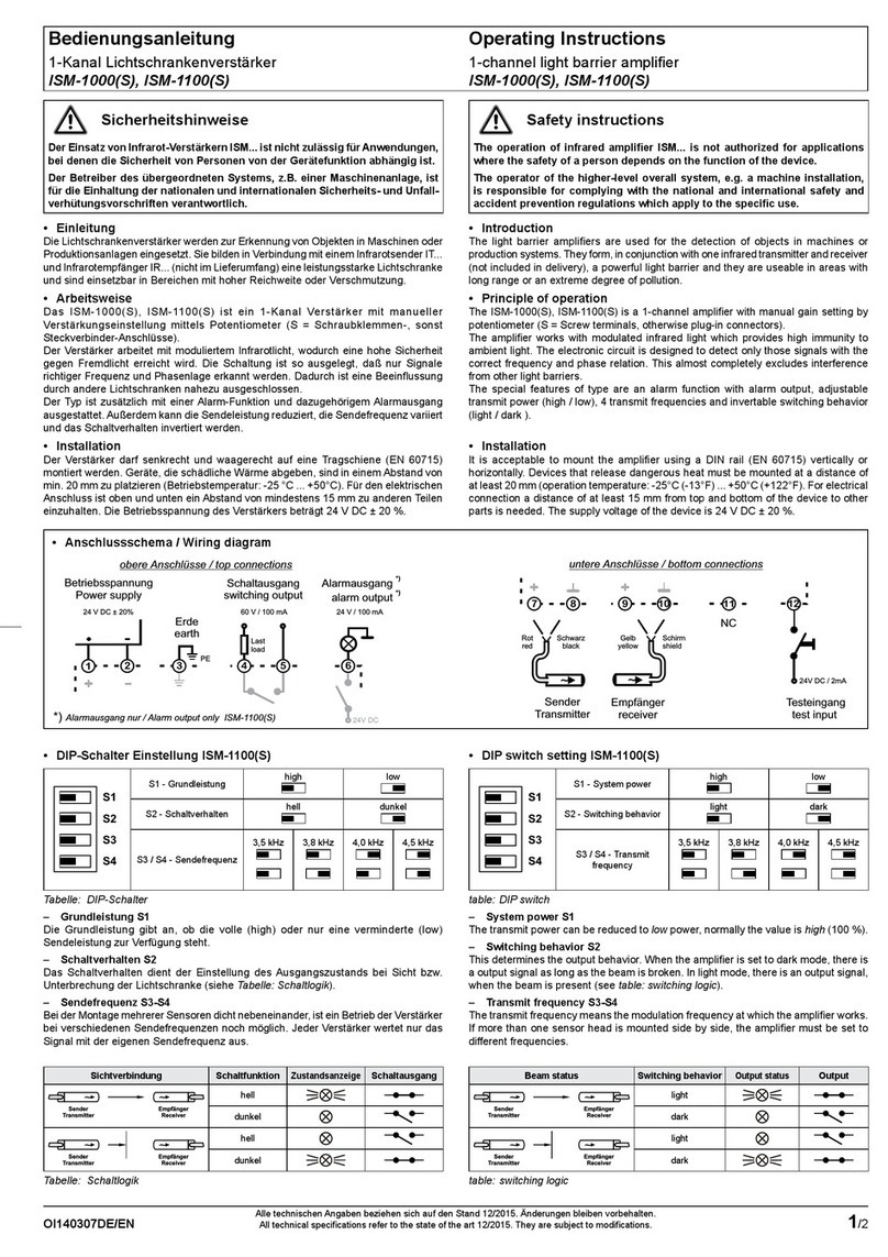
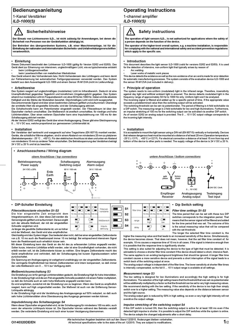
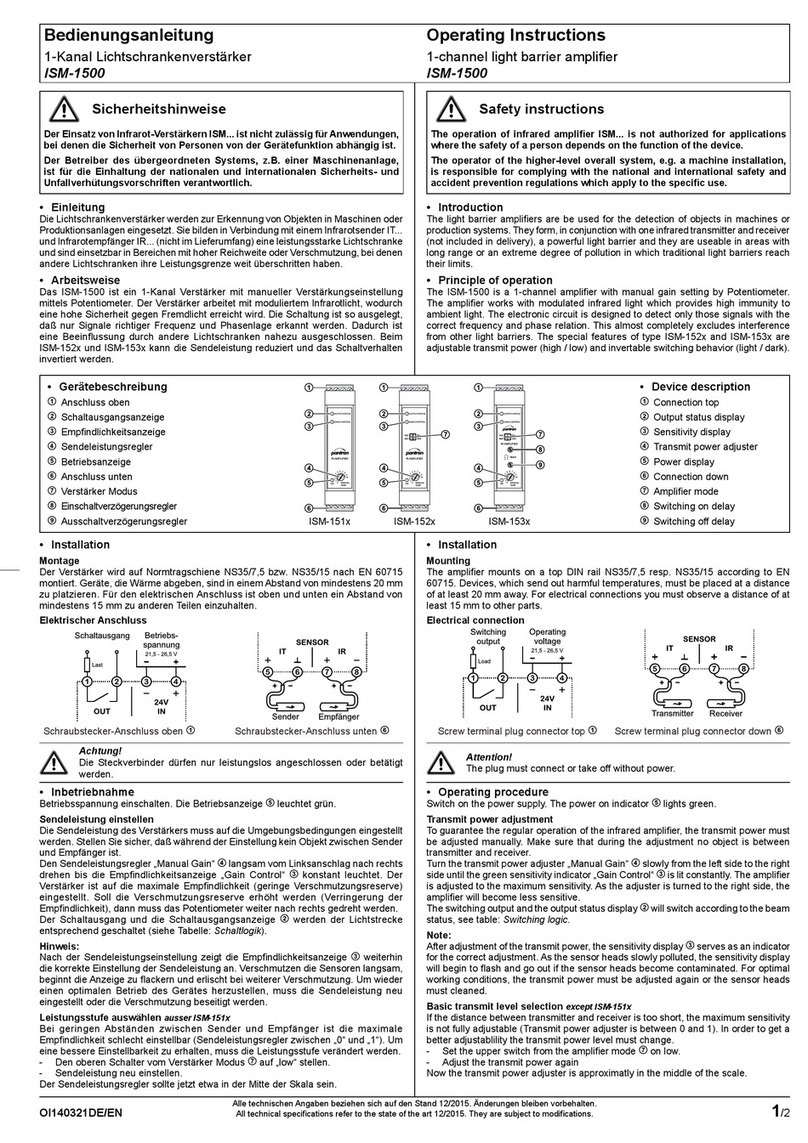
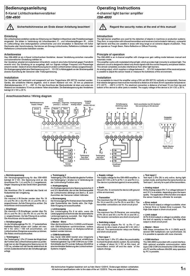
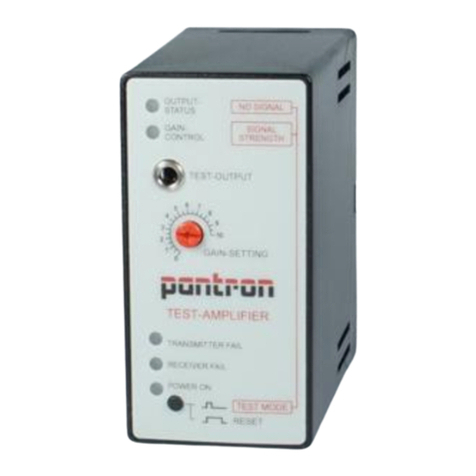
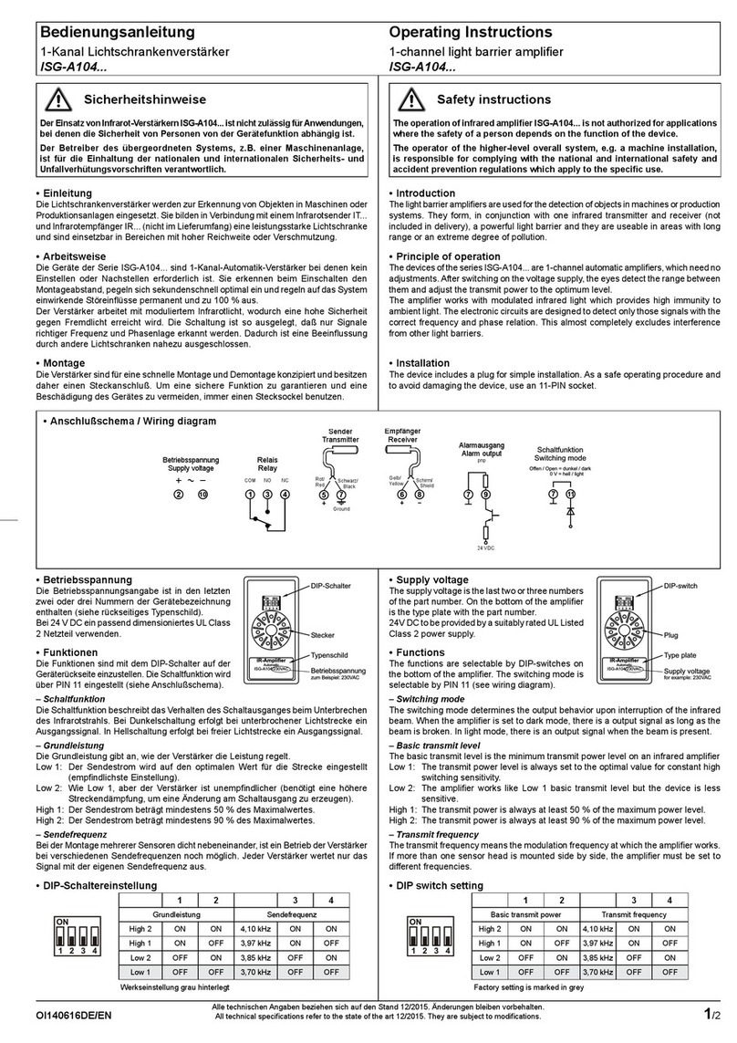
•Anschlussschema
•Introduction
Amplifiers are used as the components of a higher-level overall system for the
detection of objects.
They can only operate with one Transmitter IT... and one Receiver IR....
•Principle of operation
TheISM-1000(S) resp. ISM -1100(S) is a 1-channel amplifier with manual gain setting
by Potentiometer. ( S = Screw terminals, otherwise plug-in connectors)
The amplifier works with modulated infrared light which provides high immunity to
ambient light. The electronic circuit is designed to detect only those signals with the
correct frequency and phase relation. This almost completely excludes interference
from other light barriers.
The special features of type ISM-1100(S) are an alarm function with alarm output,
adjustabletransmitpower(high/low),4transmitfrequenciesandinvertableswitching
behavior (light / dark ).
•Installation
The amplifier with rail mounting (DIN 43880) is allowed to mount vertikal and hori-
zontal. Devices, which send out harmfull temperature, have to place with a distance
of 20 mm (Operation temperature ISM-1x00(S): -25°C (-13°F)...+50°C (+122°F). For
electrical connection, you have to observe a distance with at least 15 mm to other
devices.
Also you have to note the supply power about 24 V DC ± 20 %.
•Wiring diagram
24V DC
Betriebsspannung
Power supply
2
13
PE
24 V DC ± 20%
2
Erde
earth
Alarmausgang
alarm output
*)
*)
6
24 V / 100 mA
Schaltausgang
switching output
5
4
Last
load
60 V / 100 mA
ISM-1000(S)
ISM-1100(S)
*)
Sender
Transmitter
Rot
red
Schwarz
black
Empfänger
receiver
Gelb
yellow
Schirm
shield
10
9
8
711 12
Testeingang
test input
24V DC / 2mA
~~
NC
*)
Alarmausgang nur / Alarm output only ISM-1100(S)
untere Anschlüsse / under connections
obere Anschlüsse / upper connections
Empfindlichkeit
Schaltverhalten
Sende-
frequenz
high low
dunkel
4,0 kHz
3,8 kHz
hell
high low
dark
light
Sensitivity
Switching
behavior
Transmit
frequency
3,5 kHz 4,5 kHz 4,0 kHz
3,8 kHz
3,5 kHz 4,5 kHz
S1
S2
S3
S4
•DIP-Schalter Einstellung ISM-1100(S)
- Grundleistung
Die Grundleistung gibt an, ob die volle (high)
oder nur eine verminderte (low) Sendeleis-
tung zur Verfügung steht.
- Schaltverhalten
DasSchaltverhaltendientzurEinstellungder
Reaktion des Schaltausgangs bei Unterbre-
chung der Lichtschranke. (siehe Tabelle:
‘Schaltlogik’)
- Sendefrequenz
Bei der Montage mehrerer Sensoren dicht
nebeneinander, ist ein Betrieb der Verstär-
ker bei verschiedenen Sendefrequenzen
noch möglich. Jeder Verstärker wertet nur
das Signal mit der eigenen Sendefrequenz
aus.
•DIP switch setting ISM-1100(S)
- System power
The transmit power can be reduced to ‘low ‘
power, normally the value is ‘high’ (100 %).
- Switching behavior
This determines the output behavior upon
interruption of the infrared beam. When the
amplifierissettodarkmode, there is a output
signal as long as the beam is broken. In light
mode, there is an output signal, when the
beamispresent.(seetable:‘switchinglogic’)
- Transmit frequency
The transmit frequency means the modula-
tion frequency at which the amplifier works.
If more than one sensor head is mounted
side by side, the amplifier must be set to dif-
ferent frequencies.
hell
light
Schaltausgang
Output
OUTPUT
STATUS
Schaltverhalten
Switching behavior
IT IR
IT IR
hell
light
dunkel
dark
dunkel
dark
Sichtverbindung
Beam status
Tabelle:Schaltlogik Table: switching logic
Tabelle: DIP-Schalter Einstellung ISM-1100 Table: DIPswitch setting ISM-1100
Bedienungsanleitung Operating Instructions
1-KanalVerstärker
ISM-1000(S)... ISM-1100(S)... 1-channelamplifier
ISM-1000(S)... ISM-1100(S)...
All technical specifications refer to
the state of the art 11/2006.
They are subject to modifications.
AlletechnischenAngabenbeziehen
sich auf den Stand 11/2006.
Änderungenbleibenvorbehalten.
2/ 2
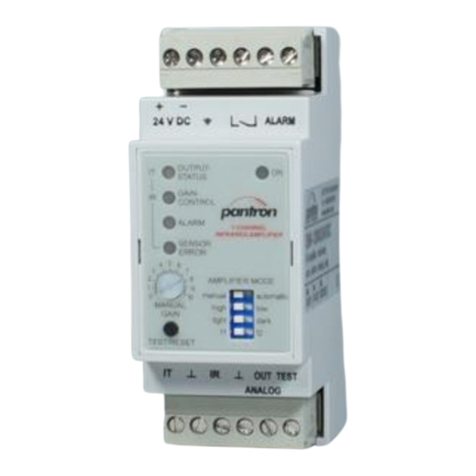
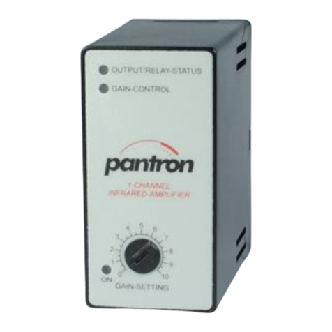
•Anzeigen und Bedienelemente
H1: Schaltzustandsanzeige - gelb
H2: Empfindlichkeitsanzeige - grün
H3: Betriebsanzeige - grün
H4: Alarmanzeige - rot
P1: Empfindlichkeitseinsteller
S1 - S4: DIP-Schalter Einstellungen
ISM-1000 ISM-1100 ISM-1000S ISM-1100S
35,8
9,5
58
89,6
95
H1
H2
P1
S1 - S4
IR-AMPLIFIER
OUTPUT-
STATUS
GAIN-
CONTROL
ALARM
ON
light
high
dark
low
MANUAL
GAIN
AMPLIFIER MODE
f1=1+3
f2=1+4
f3=2+3
f4=2+4
12
43
H3
H4
H1
H2
P1
OUTPUT-
STAT US
GAIN-
CONTROL
ON
MANUAL
GAIN
IR-AMPLIFIER
H3
•Inbetriebnahme
Vor Inbetriebnahme, wenn vorhanden, DIP-Schalter S1 - S4 am Gerät passend
einstellen. Sensoren aufeinander ausrichten. NachAnlegen der Betriebsspannung
muss der Anwender die Sendeleistung mit P1 auf die erforderliche Höhe bringen,
sodass bei Sichtverbindung H2 leuchtet. In Hellschaltung leuchtet gleichzeitig H1,
während in Dunkelschaltung nur ISM-1100(S) H1 erst bei Unterbrechung aufleuchtet
(siehe Tabelle ‘Schaltlogik’).
•Alarm und Alarmausgang nur ISM-1100(S)
DerAlarmzustand tritt ein, wenn die Sendeleistung nicht ausreichend ist.
Ursache kann z. B. eine Verschlechterung der Sicht, eine zu große Distanz oder
Dejustage der Sensoren sein. Nach Beseitigung des Fehlers erlischt dieAnzeige.
•Testeingang
Legt man an denTesteingang 24 V DC an, so schaltet der Sender ab. Es kann so die
Funktion der Lichtschranke überprüft werden.
•Operating procedure
Before operating procedure you have to choose the DIP switch setting S1 - S4 for
your application only ISM-1100(S). Sensor heads adjusts one on top of the other.After
switch on the power supply, you have to adjust the transmit power with P1 until H2
signalssufficientpower.In light switching mode H1lightstoowhereas in dark switching
mode only ISM-1100(S) H2 lights only, when the beam is interrupted. (see also table
‘Switching logic’)
•Alarm and Alarm output only ISM-1100(S)
Alarm is active, when the transmit power is not sufficient.
The cause can be e. g. deterioration of the beam, too large distance or misadjustment
of sensor heads. Is the cause removed, the alarm is no longer active.
•Test input
A voltage with a value of 24 V DC at test input switches off the transmitter beam.
With this feature you can test the system.
•Display content
H1: Switching indicator - yellow
H2: Sensitivity display - green
H3: Power On display - green
H4: Alarm display - red
P1: Gain setting
S1 - S4: DIP-switch settings
Maßzeichnungen in mm |Dimensions in mm
35,8
9,5
89,6
95
58

This manual suits for next models

3

Other Pantron Amplifier manuals

Pantron ISG-N1 Series User manual

Pantron

Pantron ISG-N1 Series User manual

Pantron ISG-A1 Series User manual

Pantron

Pantron ISG-A1 Series User manual

Pantron ISM-1500 User manual

Pantron

Pantron ISM-1500 User manual

Pantron ISM-4800 User manual

Pantron

Pantron ISM-4800 User manual

Pantron ISM-2000 User manual

Pantron

Pantron ISM-2000 User manual

Pantron ISG-A1 Series User manual

Pantron

Pantron ISG-A1 Series User manual

Pantron ILD-1000(S) User manual

Pantron

Pantron ILD-1000(S) User manual

Pantron ISM-1200 User manual

Pantron

Pantron ISM-1200 User manual

Pantron ISM-1800 User manual

Pantron

Pantron ISM-1800 User manual

Pantron ISG-N124M User manual

Pantron

Pantron ISG-N124M User manual

Pantron ISM-8000 Series User manual

Pantron

Pantron ISM-8000 Series User manual

Pantron IMX-N Series User manual

Pantron

Pantron IMX-N Series User manual

Pantron ISM-4000 User manual

Pantron

Pantron ISM-4000 User manual

Pantron ISG-N Series User manual

Pantron

Pantron ISG-N Series User manual

Pantron ISG-A101 User manual

Pantron

Pantron ISG-A101 User manual

Pantron ISG-A104 Series User manual

Pantron

Pantron ISG-A104 Series User manual

Pantron ISM-8800 User manual

Pantron

Pantron ISM-8800 User manual

Pantron ISM-1000 User manual

Pantron

Pantron ISM-1000 User manual

Pantron ISM-1220S User manual

Pantron

Pantron ISM-1220S User manual

Popular Amplifier manuals by other brands

Philips PM 3419A Service manual

Philips

Philips PM 3419A Service manual

Musical Fidelity A5 CR Instructions for use

Musical Fidelity

Musical Fidelity A5 CR Instructions for use

ADS M860 instruction manual

ADS

ADS M860 instruction manual

Deaf Bonce APOCALYPSE ATOM PRO Series owner's manual

Deaf Bonce

Deaf Bonce APOCALYPSE ATOM PRO Series owner's manual

Life Changer icOn 4PRO owner's manual

Life Changer

Life Changer icOn 4PRO owner's manual

Omron E3X-NH manual

Omron

Omron E3X-NH manual

M-system 20VS5-500 instruction manual

M-system

M-system 20VS5-500 instruction manual

Panasonic RAMSA WP-1200B/G Specifications

Panasonic

Panasonic RAMSA WP-1200B/G Specifications

Wisi MIDI Series operating instructions

Wisi

Wisi MIDI Series operating instructions

McIntosh MA352 owner's manual

McIntosh

McIntosh MA352 owner's manual

Sinfoni Tempo Andante owner's guide

Sinfoni

Sinfoni Tempo Andante owner's guide

thomann the t.amp S-75 MK II user manual

thomann

thomann the t.amp S-75 MK II user manual

Ground Zero DSP Series manual

Ground Zero

Ground Zero DSP Series manual

Behringer Ultragain Pro MIC2200 quick start guide

Behringer

Behringer Ultragain Pro MIC2200 quick start guide

Keces E40 user manual

Keces

Keces E40 user manual

Sony TA-FA30ES operating instructions

Sony

Sony TA-FA30ES operating instructions

Sony XM-2751 operating instructions

Sony

Sony XM-2751 operating instructions

Pioneer SA-710 operating instructions

Pioneer

Pioneer SA-710 operating instructions

manuals.online logo
manuals.online logoBrands
  • About & Mission
  • Contact us
  • Privacy Policy
  • Terms and Conditions

Copyright 2025 Manuals.Online. All Rights Reserved.