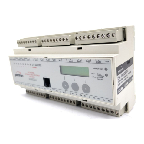
Operating instructions
Amplifier ISG-A1...
November 1999, subject to change
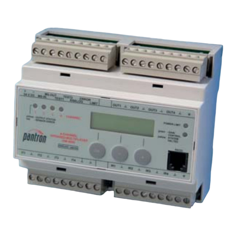
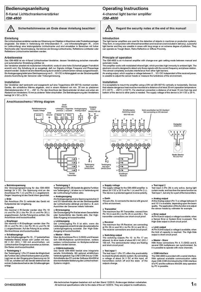
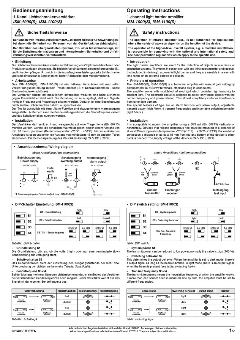
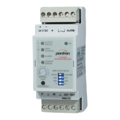
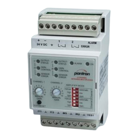
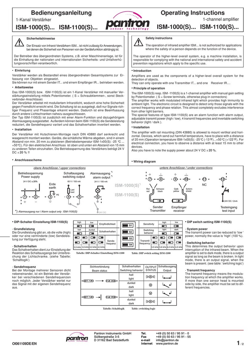
Display contents:
H1: Switching indicator
H2: Automatic level display
H3: Alarm display
H4 und H5:Transmit frequency display
H6 und H7:Basic transmit level display
P1: Switching on delay
P2: Switching off delay
S1: Test/reset button
Pantron Automation Inc.
P.O. Box 6039
Gastonia, NC 28056
Tel: (704) 864 1400
Fax: (704) 864 0120
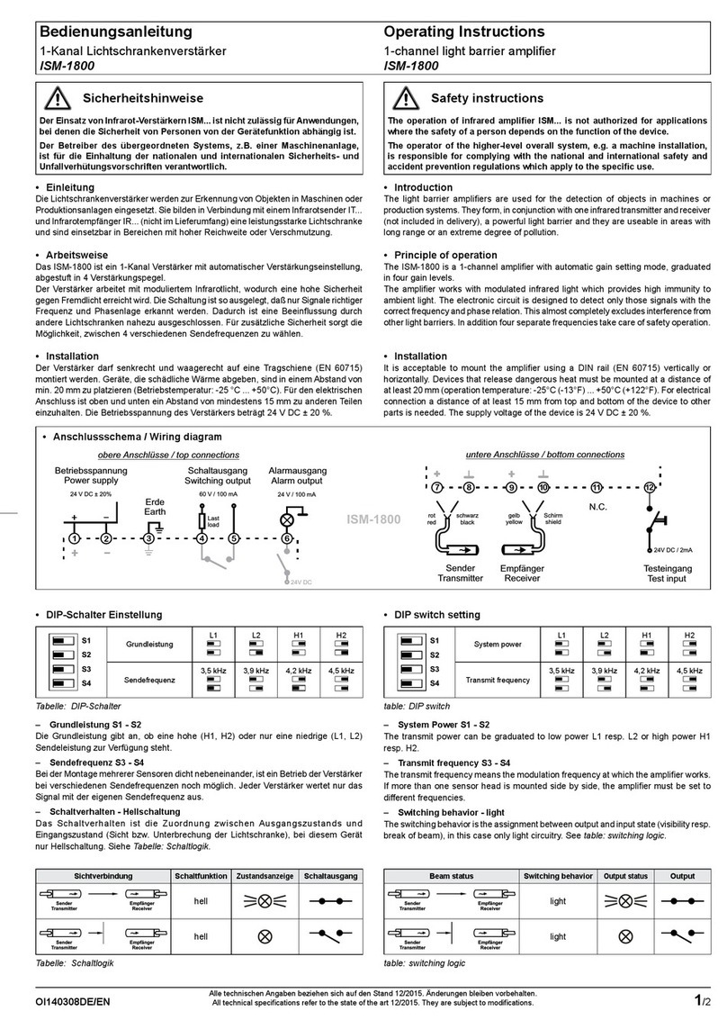
ISG-A11x ISG-A12x ISG-A13x ISG-A14x
Operation mode terminolgy
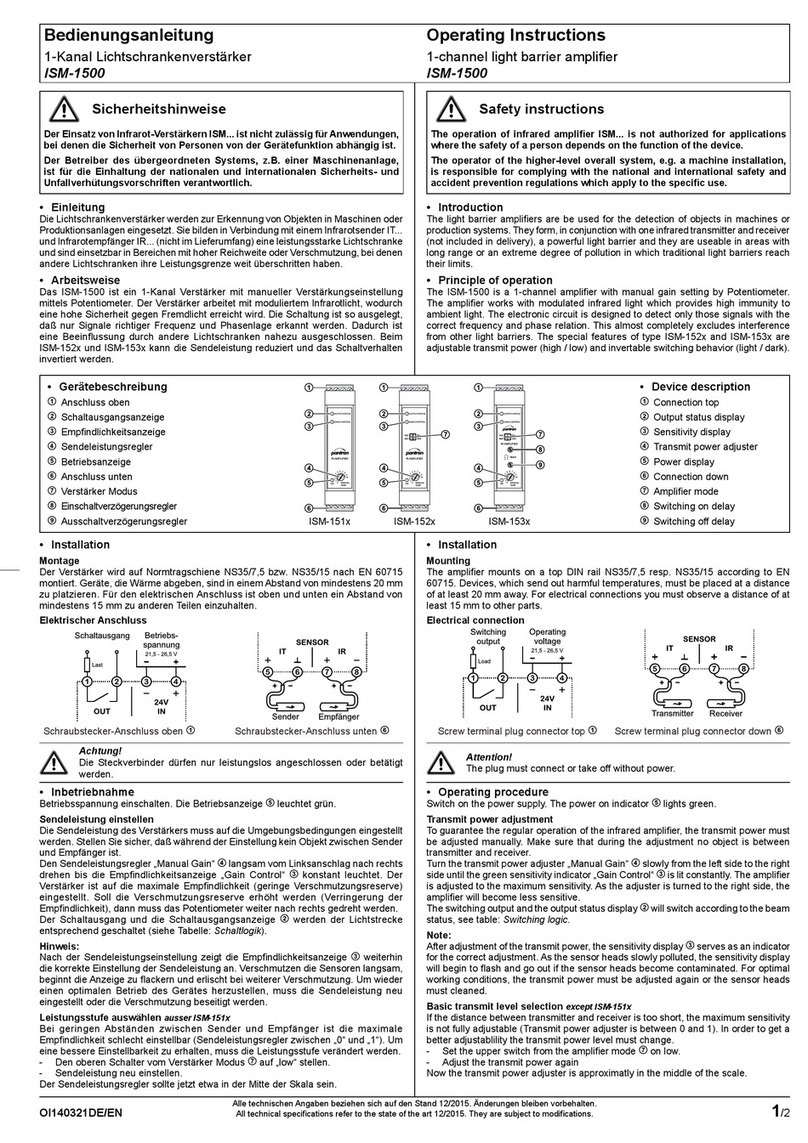
- Normal operation mode
If visual contact exists between transmitter and
receiver, the LED H2 lights.The ALC is active
and the transmit power will be turned
automatically on the optimum. If the sensor
heads pollute very slow the amplifier raises
the transmit power. At 95 % of the maximum
transmit power, the alarm display H3 lights
and the alarm output is active (24 V DC). If
the infrared beam is interrupted, the display H2
is off and the transmit power level will be
constant until the infrared beam is clear again.
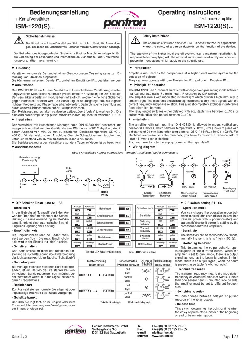
For a description of how the amplifier works, see
table switching logic. The switching on and
off delay is adjustable between 0...10 s with
the potentiometer P1 and P2 (only ISG-A13x).
- Test mode (except ISG-A11x)
In the test mode the amplifiers check the
sensor heads and the signal quality.Toenter
the test mode, press the S1 botton.
a) Signal strength
The display H2 flashes between 1 and 10
times. The flashes are proportional to the
received signal.
b) Error
The display H3 flashes red. Another LED
describes the mistake exactly:
cigolgnihctiwS
sutatsmaeB gnihctiwS
edom
tuptuO
rotacidni
yaleR
tuptuo
rotsisnarT
tuptuo
thgilCDV42
krad0
thgil0
kradCDV42
H1 flashes - no signal
The Sensor heads are OK.The transmit
signal can not be received.
H4 flashes - transmitter fail
like H3: The resistance is too high.
The transmitter isnt con-
nected or the cable is broken.
faster than H3: The resistance is too low. The
transmitter has a short circuit.
H5 flashes - receiver fail
like H3: The resistance is too high.
The receiver isnt connected
or the cable is broken.
faster than H3: The resistance is too low. The
receiver has a short circuit.
- Teach mode (only ISG-A14x)
In Teach mode, the switching points are
programmed by the user for each specific
application. Two teach modes are
possible:
Level1: The object should be recognized
Level2: The object shouldn’t be recognized
Programming execution:
Put the object between the Sensor heads and
push the button S1. The display H2 flashes.
If the teach mode completes successful, the
display H2 lightsconstantly.
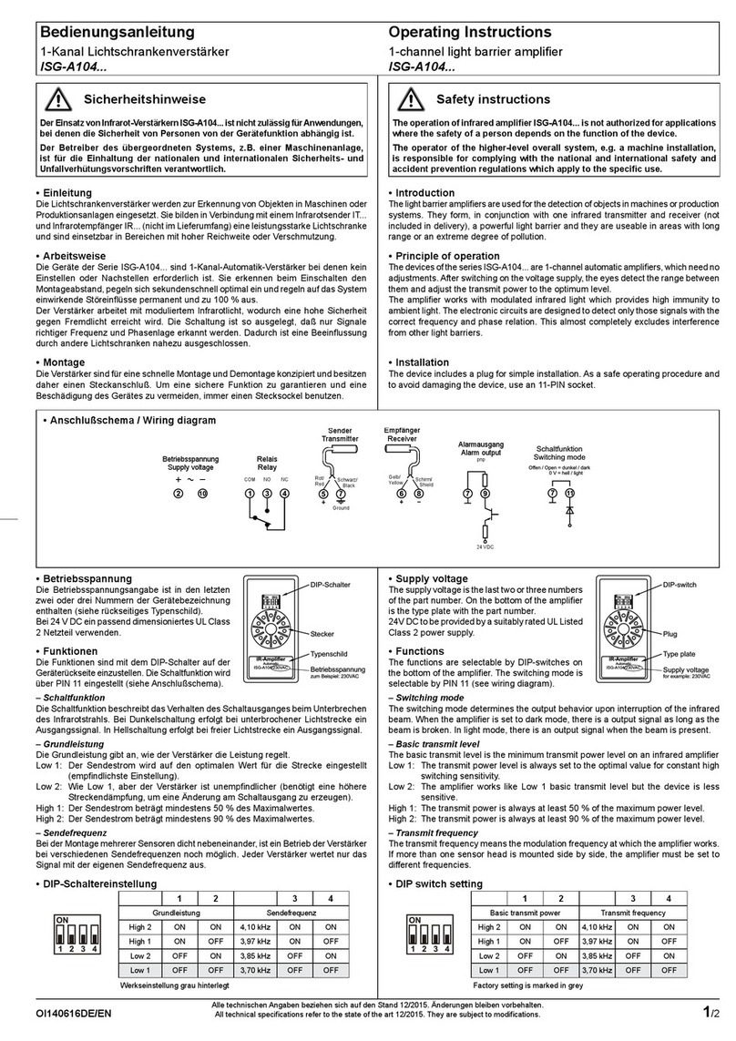
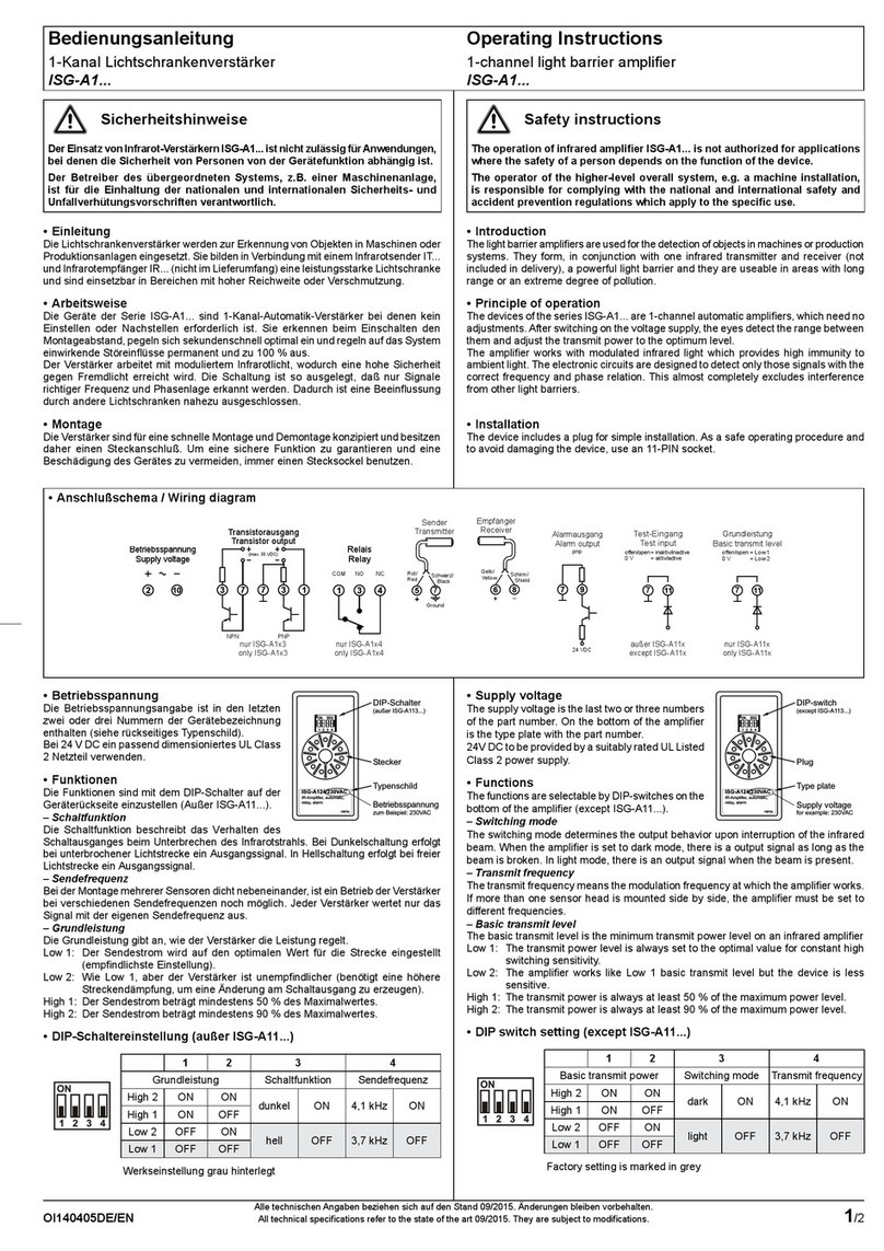
- Basic transmit level
The basic transmit level is the minimum trans-
mit power level of an infrared transmitter.
Low1: The transmit power level is always set
to the optimal value for constant high
switching sensitivity.
Low2: The amplifier works like the low 1
basic transmit level but the device is
less sensitive.
High1: The transmit power is always at least
50 % of the maximum power level.
High2: The transmit power is always at least
90 % of the maximum power level.
Function terminolgy
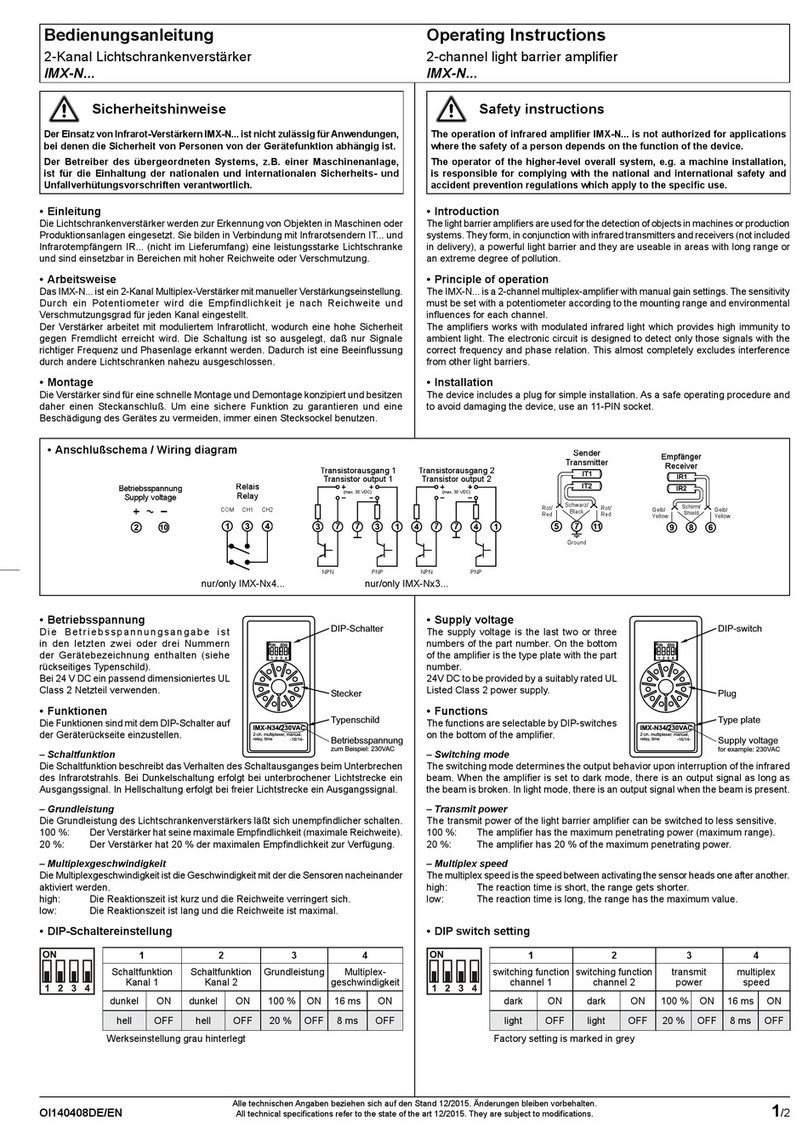
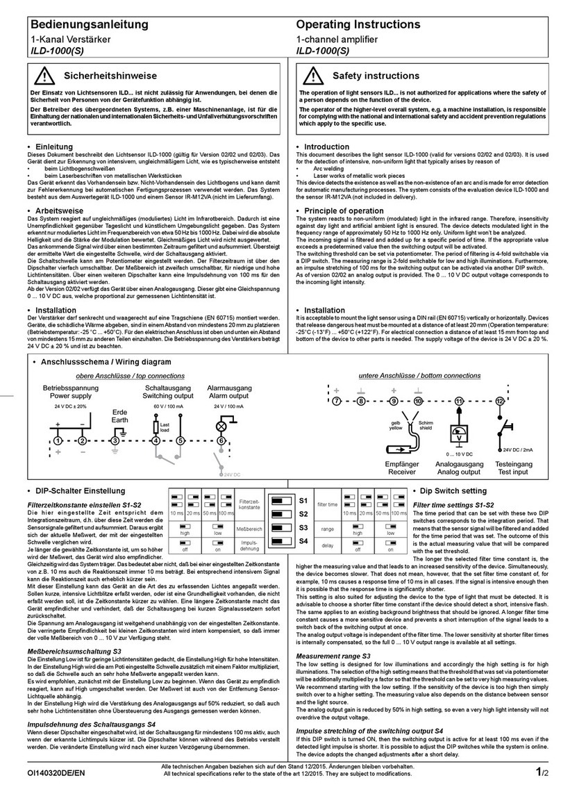
- Switching mode
The switching mode describes the output
behavior on clearance of the infrared beam.
The differences between light and dark
switching modes are shown in the switching
logic table shown above.
- Transmit frequency
The transmit frequency means the modulation
frequency at which the amplifier works. If more
than one sensor head is mounted in close
proximity, the amplifiers must be set to
different frequencies.
