Refrigerating Specialties Division 2
Important Note:
The motor cover should be kept on the motor at all times to
protect it from dust and mechanical damage. No lubrication of
the motor is required.
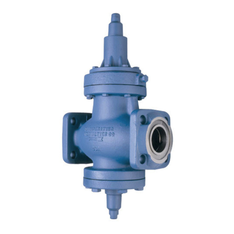
PRINCIPLES OF OPERATION, A4AM (SEE FIG. 1)
Themotorwillrespondto a signalfrom a suitablecontroller, for
example, a thermostat. When the temperature at the sensing
element changes the thermostat, the motor responds immedi-
ately to the signal by rotating the motor shaft. This rotation is
transmittedthroughthecamtothevalvestemandrangespring
tochange theset-point bychanging the springpressure acting
on top of the diaphragm. Whether used as part of a cooling
system to control evaporator pressure, or as part of a heat
reclaim system to control condensing pressure, an increase in
temperature at the thermostat will decrease the spring pres-
sure and lower the inlet pressure thus lowering the evaporator
or condenser temperature. Normally cam rotation is 160 de-
grees and one minute of time is required for the full cam
rotation. Amotorwith240degreesand1.5minuterotationtime
is available and must be so ordered.
TheprinciplesofoperationoftheA4AMSeriesarethesameas
forthebasicA4regulator except forthe varying set-pointof the
motorized pressure pilot. The inlet refrigerant pressure enters
thespace underthe diaphragmthrough passageN. When the
force created by the inlet pressure exceeds the varying spring
force, the diaphragm is lifted off of the pilot seat allowing
pressure to enter the top of the power piston. This causes the
powerpistontomove downward forcingthe modulating plugto
open and modulate to maintain the varying set-point pressure
as dictated by the temperature controller signal to the motor.
An increase in refrigerant inlet pressure, above the set-point
pressure setting, lifts the diaphragm further to allow more
pressureontop ofthe powerpistonand opens thevalvewider.
A decrease in inlet pressure, below the varying set-point
pressure setting, causes the diaphragm to move closer to the
pilot seat reducing the pressure to the top of the piston and
causing the closing spring to reduce the valve opening. The
pressure on top of the piston is controlled by the flow through
the bleed hole in the power piston and through the clearances
between the piston and main valve cylinder. A minimum of 2
psi (0.14 bar) pressure drop across the valve is required in
order for it to open fully.
ADJUSTMENT A4AM
Adjust the controller sensitivity to the desired point according
to the manufacturer’s directions. Open the regulator manually
(manualopeningstembackedout)andrunthesystemuntilthe
temperature at the sensing element reaches the desired level.
Adjust the controller (thermostat) setting to a reading that will
cause the cam of the motor to rotate and stop in center cam
position. Put the regulator back into automatic operation by
turning the manual opening stem in until just the flats on the
stemarevisible. Loosen the pressureadjusting screwlocknut
and turn the adjusting screw until the desired inlet pressure for
this temperature and load condition is reached. Turning the
adjustingscrewinwilllowerthepressure;turningitoutwillraise
the pressure. If after several hours of operation the tempera-
ture is not as desired, readjust the pressure adjusting screw
slightly. Once the desired setting is reached, make sure the
lock nut is tightened. The valve will now modulate in response
to load variation to maintain constant temperature.
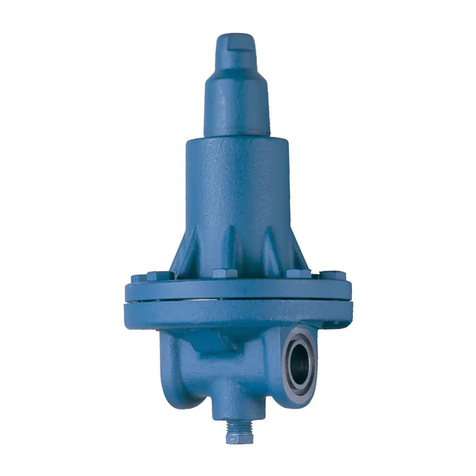
PRINCIPLES OF OPERATION, A4AOM (SEE FIG. 2)
Thispressureregulatormodulatestheoutletpressureinaccor-
dance to load requirements as sensed by an electric thermo-
stat or humidistat that varies an electric signal applied to a
motor mounted on the regulator pilot. The motor operation is
describedabove forA4AM, exceptthe A4AOM operatesas an
outlet pressure regulator. Available in standard Range V or
Range D.
Theoutletpressureissensedunderthediaphragmthroughthe
sensing tube, which is part of the Flange Ring-tube assembly.
Whenthe force createdby the outletpressure acting underthe
diaphragm is less than the force of the range spring, the pilot
plug is open, allowing pressure to enter on top of the piston.
Thiscausesthepowerpistontoforcethethrottlingplugtoopen
to maintain constant outlet pressure. Decrease in the outlet
pressure allows the range spring to open the pilot plug further,
allowing more pressure on top of the piston and opening the
throttlingplugfurther. An increasein theoutletpressure will lift
the diaphragm against the force of the range spring, allowing
thepilot plug tostart closing. The pressureontop ofthepower
piston is decreased and the closing spring acts to reduce the
opening of the throttling plug and the flow of fluid through the
regulator. Thepressureontopofthepowerpistoniscontrolled
bytheflow through the pilotseatandthebleed through ableed
hole in the power piston and through the clearance between
the piston and the cylinder. A minimum of 2 psi (0.14 bar)
pressure drop across the regulator is required to open it fully.
ADJUSTMENT A4AOM
Adjust the controller sensitivity to the desired point according
to the manufacturer’s directions. Open the regulator manually
(manualopeningstembackedout)andrunthesystemuntilthe
temperature at the sensing element reaches the desired level.
Adjust the controller (thermostat) setting to a reading that will
cause the cam of the motor to rotate and stop in center cam
position. Put the regulator back into automatic operation by
turning the manual opening stem in. Loosen the pressure
adjusting screw lock nut and turn the adjusting screw until the
desired inlet pressure for this temperature and load condition
is reached. Turning the adjusting screw in will lower the
pressure; turning it out will raise the pressure. If after several
hours of operation the temperature is not as desired, re-adjust
thepressureadjustingscrew slightly. Once thedesired setting
is reached, make sure the lock nut is tightened. The valve will
now modulate in response to load variation to maintain con-
stant temperature.
MANUAL OPENING STEM:
All Type A4 Regulators are provided with a manual opening
stem. To open the regulator manually, back the stem out (turn
counter-clockwise) until it stops. To put the regulator into
automatic operation, turn the stem in (clockwise) until only the
flats on the stem protrude from the packing nut.
