manuals.online logo
Brands
  1. Home
  2. •
  3. Brands
  4. •
  5. Parker
  6. •
  7. Controllers
  8. •
  9. Parker Sporlan S3C User manual

Parker Sporlan S3C User manual

S3C Case Control
Quick Reference Guide
The Sporlan S3C Case Control should be installed only by a qualified professional. All other system components
should be supplied by Sporlan to ensure compatibility and proper operation.
1. INSTALLATION
(Reference diagram on back side).
1. Mount the controller in a rain-tight
protected location using #8 sheet metal
screws; tighten to 14-16 in-lbs. DIN rail
may also be used as alternate mounting.
The suggested mounting area is 6 inches
high and 14 inches wide, depth is 3 inches.
2. Mount the suction temperature sensor
to the suction line after the evaporator.
Connect the non-polarized sensor wires to
“Coil Out” on the controller. Maximum
torque on screw terminals is 3.5 in-lbs.
3. Mount the defrost termination sensor to
the coil. Connect the non-polarized sensor
wires to “Def Term” on the controller.
4. Mount the discharge air temperature sen-
sor in the appropriate location in the case.
Connect the non-polarized sensor wires to
“Dsch Air” on the controller.
5. Mount the pressure transducer on the
suction line near the suction temperature
sensor, positioned at 12 o’clock. Install
the pressure transducer cable and connect
the wires to “Pressure” on the controller.
Black = “5V”, White = “S”, Green = “Gnd”.
Use caution when working around high voltage components.
Safety covers should be used for personal safety on high voltage panels.
6. Connect the liquid line solenoid to “Sol/
Pulse” on the controller.
7. Connect the Electronic Expansion Valve
to “Stepper Valve” on controller. For alter-
nate valve configurations, see Bulletin
100-50-9.1.
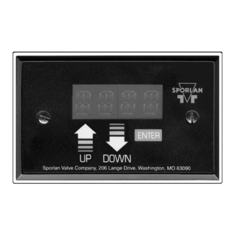
8. Install the S3C DM (display) and wire to
the controller.
9. Connect power supply to the controller
and DM. Transformer requirements are
24VDC 60VA, Class II.
2. SETUP
On initial power up, the display will show
 and the controller will drive the stepper
valve closed until set up is complete. Scan QR
code below for full installation and operating
manual.
Congure the controller using an S3C DM
(display). Press “UP” or “DOWN” arrow on
the display to view parameter options. Press
“SET” to save. Press “ESC” button to back up
one level in the menu. e set up must be
complete prior to exiting otherwise changes
will not be saved.
1. Is the case self contained (): Select
, then press SET
2. Set , Case Identier
3. Set , Application Type:
  (Walk In Cooler/Freezer)
  (Single Temperature)
  (Dual Temperature)
4. Set , Stepper Conguration:
  (Electronic Pressure Regulator)
  (Electronic Expansion Valve)
  (Use for TEV)
5. Set , Expansion Valve Type:
 1 
 
 1
Temperature sensor should be mounted at
either 4 or 8 o’clock, on a free-draining line.
Sporlan S3C Case Control
Installation and Operation Manual
SD-429 / 32022
6. Set , Number of Evaporators
7. Will case be integrated to a , Building
Automation System;  or 
8. Set , Building Automation Protocol
(skipped if no BAS):
  (MODBUS over RS-485)
  (BACnet over RS-485)
  (BACnet over IP)
  (MODBUS over IP)
9. Set , Month
10. Set, Day
11. Set, Year
12. Set, Time (24hr format)
13. Set , Refrigerant Type
14. Set , System EPR Type
15. Set , Discharge Air Setpoint
16. Set , Defrost Type
 , Hot Gas
 , Electric
 , Air
17. Set , Defrost Termination
Temperature
18. Set , Defrost Termination Failsafe
Time
19. Set , Defrost Per Day
For detailed instructions and part numbers,
scan this QR code or go to
solutions.parker.com/literature-100
and download Bulletin 100-50-9.1.
+–
SSR
RS-485 COMM
(TO BAS)
Suction
Temperature
Sensor
N
L
Pressure
Transducer
L1
L2
EEV
Liquid Line
Solenoid Valve
10”-14”
minimize
1”- 2”
ideal
Evaporator
Refer to the evaporator manufacturer’s
installation/orientation instructions.
Discharge Air
Anti-Sweat
Heater
Defrost
Termination Sensor
White
Green
Black
Red
Green
White
Black
Drain
Sensor
Occ.
Sensor
Humidity
Sensor
24VDC
60W
MIN
DM
D+
D-
GND
24V
%
Lights
Fans
Defrost
Contactor
INTERNALLY FUSED -
Sol/Pulse: 1A @ 240VAC
Fans, Lights, Defrost: 6A @ 240VAC
Anti-Sweat Output to SSR: 5 VDC @ 40mA
Green
Black
Red
Green
Black
Red
White
Black
Red
Parker Hannin Corporation
Sporlan Division
206 Lange Drive • Washington, MO 63090 USA
phone 636 239 1111 • fax 636 239 9130
www.sporlan.com
SD-429 / 32022© 2022 Parker Hannin Corporation
⚠WARNING – USER RESPONSIBILITY
Failure or improper selection or improper use of
the products described herein or related items
can cause death, personal injury and property
damage.
This document and other information from
Parker Hannifin Corporation, its subsidiaries and
authorized distributors provide product or system
options for further investigation by users having
technical expertise.
The user, through its own analysis and testing, is
solely responsible for making the final selection
of the system and components and assuring that
all performance, endurance, maintenance, safety
and warning requirements of the application are
met. The user must analyze all aspects of the
application, follow applicable industry standards,
and follow the information concerning the
product in the current product catalog and in
any other materials provided from Parker or its
subsidiaries or authorized distributors.
To the extent that Parker or its subsidiaries
or authorized distributors provide component
or system options based upon data or
specifications provided by the user, the user is
responsible for determining that such data and
specifications are suitable and sufficient for all
applications and reasonably foreseeable uses of
the components or systems.
Diagram for reference only. Refer to input/output electrical ratings for all external connections.
For safety information, see the Safety Guide at www.parker.com/safety or call 1-800-CPARKER.
Visit www.sporlan.com for details on other Sporlan products such as sensors, transducers, and valves.
Note: Use caution when working
around high voltage components.

Other manuals for Sporlan S3C

4

Other Parker Controllers manuals

Parker IQAN-LST User manual

Parker

Parker IQAN-LST User manual

Parker A4W Series Operating and installation instructions

Parker

Parker A4W Series Operating and installation instructions

Parker 507 Series User manual

Parker

Parker 507 Series User manual

Parker ERV Series Operating and maintenance instructions

Parker

Parker ERV Series Operating and maintenance instructions

Parker Lucifer EPP4 P4BG4 Series User instructions

Parker

Parker Lucifer EPP4 P4BG4 Series User instructions

Parker PAC340 User manual

Parker

Parker PAC340 User manual

Parker P2M Node 24 DO User manual

Parker

Parker P2M Node 24 DO User manual

Parker AC650V Series User manual

Parker

Parker AC650V Series User manual

Parker 506 Series User manual

Parker

Parker 506 Series User manual

Parker A4WO User manual

Parker

Parker A4WO User manual

Parker Compax3 Fluid T40 User manual

Parker

Parker Compax3 Fluid T40 User manual

Parker 650G series User manual

Parker

Parker 650G series User manual

Parker ACR7000 Series User manual

Parker

Parker ACR7000 Series User manual

Parker Lucifer EPP4 Series User instructions

Parker

Parker Lucifer EPP4 Series User instructions

Parker iqan-mc3 User manual

Parker

Parker iqan-mc3 User manual

Parker HAUSER HPLA Series User manual

Parker

Parker HAUSER HPLA Series User manual

Parker ACR7000 Series User manual

Parker

Parker ACR7000 Series User manual

Parker AC30 series User manual

Parker

Parker AC30 series User manual

Parker AC30V Series User manual

Parker

Parker AC30V Series User manual

Parker Sporlan S3C User guide

Parker

Parker Sporlan S3C User guide

Parker PTR Series Datasheet

Parker

Parker PTR Series Datasheet

Parker Gemini GV6K Series User manual

Parker

Parker Gemini GV6K Series User manual

Parker IPA Series Manual

Parker

Parker IPA Series Manual

Parker 690+ series User manual

Parker

Parker 690+ series User manual

Popular Controllers manuals by other brands

Mateksys F722-SE Basic Manual

Mateksys

Mateksys F722-SE Basic Manual

KFM 92 Series operating instructions

KFM

KFM 92 Series operating instructions

Johnson Controls Unitary Products YCCS TEC2603-4 BACnet installation instructions

Johnson Controls Unitary Products

Johnson Controls Unitary Products YCCS TEC2603-4 BACnet installation instructions

Hoffman Controls 865D Series Installation and operating instructions

Hoffman Controls

Hoffman Controls 865D Series Installation and operating instructions

Carel AT-th Tune manual

Carel

Carel AT-th Tune manual

esera ECO 503 quick guide

esera

esera ECO 503 quick guide

Edwards PGC202 instruction manual

Edwards

Edwards PGC202 instruction manual

Mitsubishi Electric MELSERVO MR-JET-G-N1 user manual

Mitsubishi Electric

Mitsubishi Electric MELSERVO MR-JET-G-N1 user manual

Magnum Energy ME-AGS-N owner's manual

Magnum Energy

Magnum Energy ME-AGS-N owner's manual

Cleanflight Seriously Pro manual

Cleanflight

Cleanflight Seriously Pro manual

Carel uAM user manual

Carel

Carel uAM user manual

cashco 8310HP-1+8 Installation, operation & maintenance manual

cashco

cashco 8310HP-1+8 Installation, operation & maintenance manual

Antec Fume Hood Controller Series manual

Antec

Antec Fume Hood Controller Series manual

Madas FRG/2MB manual

Madas

Madas FRG/2MB manual

Cutler-Hammer EATON Ampgard Mark V instructions

Cutler-Hammer

Cutler-Hammer EATON Ampgard Mark V instructions

Continental Instruments CICP1300 datasheet

Continental Instruments

Continental Instruments CICP1300 datasheet

Gewiss CHORUS GWA9140 user manual

Gewiss

Gewiss CHORUS GWA9140 user manual

Linear Technology LTC4266A manual

Linear Technology

Linear Technology LTC4266A manual

manuals.online logo
manuals.online logoBrands
  • About & Mission
  • Contact us
  • Privacy Policy
  • Terms and Conditions

Copyright 2025 Manuals.Online. All Rights Reserved.