manuals.online logo
Brands
  1. Home
  2. •
  3. Brands
  4. •
  5. Parker
  6. •
  7. Controllers
  8. •
  9. Parker XLT Series Datasheet

Parker XLT Series Datasheet

1
ParkerHannifinCorporation
AutomationActuatorDivision
135QuadralDrive
Wadsworth,Ohio44281
Telephone330/336-3511
Facsimile330/334-3335
PM-XLT-B
Service Information & Parts List
Issued: February 15, 1994
Supersedes: April 1, 1992
B. Reassembly Procedure.
1. Apply a few drops of Loctite RC/609 to the outside
diameter of the bearings, #15.
2. Press the four bearings, #15 into housing, #5.
3. Press the four seals, #14 into the housing, #5 securing
the bearings with no play.
4. Apply a liberal amount of bearing lubricant to all four
bearings.
NOTE: Recommended lubricant is Synco Super Lube with
Teflon or compatible NLG1 Grade 2 grease.
5. Replace cylinder, #1. Install using nut, #11.
6. Replace support shafts, #16 and tool plate, #13.
7. Screw piston rod of cylinder into tool plate and tighten
locknut, #12.
8. Replace bumpers & stop collars.
(Applies to bumper option only.)
9. Install fittings and/or flow controls.
MOUNTING
The XLT Thrust Slide incorporates square nut "T" slots on all
mounting surfaces and two through holes. The "T" slot feature
allows the slide housing to be positioned after mounting. An
assortmentofsquarenutsareincludedwiththeslidetofacilitate
mounting. Additional square nuts can be ordered - each kit
contains 8 square nuts (4 primary, 4 secondary).
LUBRICATION
The pneumatic cylinder and internal bearings are pre-lubricated
at the factory and are suitable for non-lubricated applications.
However,additionalairlinelubrication will increase the lifeofthe
unit.
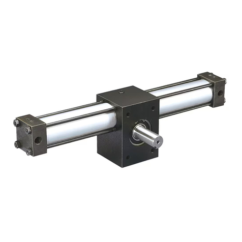
XLT Series Thrust Slide
Maintenance Instructions & Parts List
Provide Model Number and Serial Number When Ordering Spare Parts.
Model Kit Number
04 NK04
06 NK06
08 NK08
12 NK12
GENERAL
XLT Series Thrust Slides are pneumatic linear actuators that
incorporate linear ball bearings and support shafts which pro-
vide positive load support and torque resistance.
This manual contains maintenance instructions, replacement
parts information and information on various slide options.
Consult the factory or product catalog for additional information.
SPECIFICATIONS
•Maximum Operating Pressure: 100 psi
• Operating Characteristics: Double Acting Standard
(Single Acting Available)
• Four Support Rod Sizes: 1/4", 3/8", 1/2", 3/4"
• Output Force @ 60 psi: 15 - 105 lb
• Maximum Breakaway Pressure: 5 psi
• Operating Temperature Range:
Standard 0° to +180°F
Viton Seals 0° to +250°F
• 304 Stainless Steel Cylinder Body
• Stainless Steel Piston Rod
• Mounting: Unrestricted
A. Inspection and Replacement Procedure for Bearings,
Seals, Support Shafts and Cylinder.
1. Loosen locknut #12.
2. Remove stop collar, #7 and bumper, #6.
(Applies to bumper option only.)
3. Unscrew cylinder piston rod from tool plate, #13 and
remove tool plate with shafts, #16 from housing, #5.
4. Remove fittings from cylinder ports.
5. Remove nut, #11.
6. Pull cylinder, #1 from slide housing, #5.
7. Remove the four press fit seals, #14.
8. Remove the four bearings, #15.
9. Inspect cylinder, bearings, seals and support shafts
and replace if necessary.
10. Clean all parts thoroughly.
2
BUMPER/ADJUSTABLE STOP COLLARS (B)
Bumpers absorb shock, reduce noise, permit faster cycle
times and increase production rates. They can be placed on
the extend, retract or both positions.
Adjustable stop collars are only available when bumpers are
specified. They are standard on extend and provide stroke
adjustment in the extend position. For stroke adjustment in
the retract position, an adjustable stop collar can be spcified.
When bumpers and adjustable stop collars are specified for
the retract position, the stroke of the unit is DECREASED by
the "W" dimension provided in the table below.
RIGHT ANGLE FLOW CONTROL (F, G)
Right angle flow control valves allow precise adjustment of
cylinder speed by metering exhaust air flow. The Prest-Lok
design and 360° orientation capability provide a simple
means of plumbing the unit.
Right angle flow controls are designed to permit maximum
flow in both directions and provide a wide range of adjust-
ment between the minimum and maximum speeds.
911
STANDARD UNIT - BUMPER OPTION(B) AND FLOW CONTROL OPTION (F, G)
7
6
5
3
6
7
1
2 3
16
14
13
ITEM DESCRIPTION QUANTITY
1 AIR CYLINDER 1
2 FLOW CONTROL 2
3 ADAPTER (XLT04 ONLY) 2
4 WASHER (XLT04 ONLY) 2
5 HOUSING 1
6 BUMPER 2 or 4
7 STOP COLLAR 2 or 4
8 SOCKET HEAD CAP SCREW 2
9 MOUNTING PLATE 1
10a SOCKET HEAD CAP SCREW 2
11 NUT 1
12 NUT 1
13 LOAD PLATE 1
14 SEAL 4
15 BEARING 4
16 SUPPORT SHAFT 2
4
2
4
8
12
15
10a
Model W
04 .281
06 .344
08 .406
12 .500
3
HALL EFFECT AND REED SWITCHES
Hall effect and reed switches can be specified to sense the
position of the tool plate by detecting the magnetic band on
the cylinder piston. Magnets are standard on all units.
Switches are mounted on the cylinder body and are easily
positioned. Order switches separately as well as the appro-
priate clamps shown in the table below. See specifications
for more detail.
Switching Logic: Normally Open
Voltage Rating: 85-125 VAC or 5-30 VDC*
Power Rating: 10 Watts AC or DC/Resistive Load
5 Watts AC or DC/Inductive Load
Switching
Current Range: 10-200 mA/Resistive Load
(PC, Sequencer)
10-100 mA/Inductive Load (Relay)
Switching Response: 300 Hz Maximum
Breakdown Voltage: 1.8kVACrms for 1 sec., lead to case
Min. Current for LED: 18mA
Operating Temperature: 14° to 140° F(-10° to 60° C)
Lead Wire Length: 39 inches (1 meter)
AC125V CR
R
C=
=
(Recommendedforlonger
switch life 125V AC)
Putresistorandcapacitor
paralleltoloads.
CR: Relay coil (under 2W coil ratings)
R: Resistor under 1 K ohm
C: Capacitor 0.1 µF
(Requiredforproperoperation
24V DC)
PutDiodeparalleltoloads
followingpolarityas shownbelow.
DC 12V D
D: Diode: select a Diode with the breakdown
voltage and current rating according to the load.
CR: Relay coil (under 0.5W coil rating)
CR
INTEGRAL CIRCUIT FOR
SWITCHING CONTACT PROTECTION
-
+
-
+(WHITE)
(WHITE)
BROWN**
(BLACK) (BLACK)
BLUE** BLUE**
BROWN**
* Polarity is restricted for DC operation
(+) to BROWN
(-) to BLUE
If these conections are reversed the contacts will close, but the LED will not light.
Prior to October, 1993:
(+) WHITE
(-) BLACK
**Appliesto SwitchesManufactured
After10/15/93.
4 Black
Not Used
1 Brown
3Blue
Quick
Connect
Option
Hall Effect Switch Part No.
1467150000 (PNP)
1467140000(NPN)
146715000C (NPN Quick Connect)
146714000C (NPN Quick Connect)
Reed Switch Part No.
1459030000- Standard
145903000C-Quick Connect
(RED)
SWITCH
_
+
LOAD
*WhenconnectingInductive
Load(relay,electromagnetic
valve etc.) it is recommended
toinsertprotection circuit.
Diode100V1A.(NPN
connectionshown)
Type: Solid State Type (PNP or NPN)
SwitchingLogic: NormallyOpen
SupplyVoltageRange: 5 - 30VDC
CurrentOutputRange: Up to100 mA at 5 VDC,
Up to 200 mA at 12 VDC and 24 VDC
CurrentConsumption: 7 mA at 5 VDC, 15 mA at 12 VDC,
and 30 mA at 24 VDC
SwitchingResponse: 1000 Hz Maximum
ResidualVoltage: 1.5VMaximum
LeakageCurrent: 10uAMaximum
BreakdownVoltage: 1.8kVACrms for 1 sec., lead to case
Min.Current for LED: 1mA
OperatingTemperature: 14° to 140° F (-10° to 60° C)
LeadWireLength: 39inches (1meter)
BROWN**
(BLACK)
(WHITE)
BLUE**
SWITCH LOAD
SWITCH LOAD
BROWN**
(RED)
(WHITE)
BLACK**
BLUE**
(BLACK)
BROWN**
(RED)
BLACK**
(WHITE)
(BLACK)
NPN WIRING CONNECTION
BLUE**
**Applies to SwitchesManufactured
After10/15/93.
DC 5 - 30V
DC 5 - 30V
Quick Connect
Option
1 Brown
3Blue
4 Black
Model Clamp Part Number
04 L074730056
06 L074730075
08 L074730106
12 L074730150
PNP WIRING CONNECTION
6"Lead
3 BLUE
1 BROWN
Quick Connect
Option
4 BLACK
REED SWITCH SPECIFICATIONS
HALL EFFECT SPECIFICATIONS
BLACK**
+
_
_
+
4
PROXIMITY SWITCHES (P, N)
Proximity switches sense the extend and retract positions
of the slide. The proximity switch is attached to the side of
the slide, utilizing the square nut "T" slots . The switch is
installed at the factory and does not require adjustment.
Should adjustment be necessary, care should be taken to
insure that the switch does not come into contact with the
load plate. Distance from the load plate to the switch
should be approximately .016 inches.
ELECTRICAL SPECIFICATIONS
Voltage: 10-30 VDC (3 wire) PNP or NPN
Current: 7mA at 24 VDC
OutletCurrent: 130mA
SwitchingSpeed: 1000Hz
SwitchingDistance: Steel = 1.0 mm (0.039 in)
Brass = 0.7 mm (0.028 in)
Aluminum= 0.4 mm (0.016 in)
Switchisfully encapsulated.
PNP WIRING CONNECTION
DC 10-30V
(BLUE)
(BLACK)
(BROWN)
LOAD
+
-
DC 10-30V
(BLUE)
(BLACK)
(BROWN)
LOAD
+
-
SWITCH
NPN WIRING CONNECTION
SWITCH
FAILURE OR IMPROPER SELECTION OR IMPROPER USE OF THE PRODUCTS AND/OR SYSTEMS DESCRIBED
HEREIN OR RELATED ITEMS CAN CAUSE DEATH, PERSONAL INJURY AND PROPERTY DAMAGE.
This document and other information from Parker Hannifin Corporation, its subsidiaries and authorized distributors provide
product and/or system options for further investigation by users having technical expertise. It is important that you analyze
all aspects of your application and review the information concerning the product or system in the current product catalog. Due
to the variety of operating conditions and applications for these products or systems, the user, through its own analysis and
testing,is solely responsibleformakingthefinalselection of theproductsandsystemsandassuring that allperformance,safety
and warning requirements of the application are met.
The products described herein, including without limitation, product features, specifications, designs, availability and pricing,
are subject to change by Parker Hannifin Corporation and its subsidiaries at any time without notice.
REPLACEMENT PROXIMITY SWITCH
Plug In Style Switch with Connector
Type Switch Part Number
PNP SWP-1P
M8 NPN SWP-1N
ITEM DESCRIPTION QTY.
13 LOAD PLATE 1
17 SWITCH ELBOW CONN. PNP 2
17a SWITCH ELBOW CONN. NPN 2
18 PROX SWITCH - LEAD TYPE, PNP 2
18a PROX SWITCH - LEAD TYPE, NPN 2
19 PROX SWITCH - PLUG IN, PNP 2
19a PROX SWITCH - PLUG IN, NPN 2
20a SOCKET HEAD CAP SCREW 4
21a SWITCH HOUSING 2
22 SET SCREW 2
23a SQUARE NUT 4
24 STOP COLLAR FOR PROX 1
25 PROX FLAG 1
26 SOCKET HEAD CAP SCREW 1
37 SOCKET HEAD CAP SCREW 4
38 PROX FLAG 2
13
38
37
22
26
25
24
18
17
19
21a
20a
Additional information may be obtained from the Automation
Actuator Division in Wadsworth, Ohio or from your nearest
Parker Motion & Control Distributor. WARNING
23a

This manual suits for next models

4

Other Parker Controllers manuals

Parker ACR Series Manual

Parker

Parker ACR Series Manual

Parker ADAPTOMODE A4AS Guide

Parker

Parker ADAPTOMODE A4AS Guide

Parker Sporlan S3C User guide

Parker

Parker Sporlan S3C User guide

Parker ac890 User manual

Parker

Parker ac890 User manual

Parker iqan-mc3 User manual

Parker

Parker iqan-mc3 User manual

Parker Aries User manual

Parker

Parker Aries User manual

Parker PAC340 User manual

Parker

Parker PAC340 User manual

Parker CM2115 User manual

Parker

Parker CM2115 User manual

Parker ET Series Datasheet

Parker

Parker ET Series Datasheet

Parker Lucifer EPP4 P4BG4 Series User instructions

Parker

Parker Lucifer EPP4 P4BG4 Series User instructions

Parker AC30V Series User manual

Parker

Parker AC30V Series User manual

Parker 650 Series User manual

Parker

Parker 650 Series User manual

Parker 690+ series User manual

Parker

Parker 690+ series User manual

Parker 650G series User manual

Parker

Parker 650G series User manual

Parker AC890PX Series Instruction manual

Parker

Parker AC890PX Series Instruction manual

Parker ADAPTOMODE A4A Series Guide

Parker

Parker ADAPTOMODE A4A Series Guide

Parker ACR8000 User manual

Parker

Parker ACR8000 User manual

Parker ACR9000 User manual

Parker

Parker ACR9000 User manual

Parker Compax3 Fluid T40 User manual

Parker

Parker Compax3 Fluid T40 User manual

Parker P2M Node 24 DO User manual

Parker

Parker P2M Node 24 DO User manual

Parker A4AP-DN Manual

Parker

Parker A4AP-DN Manual

Parker 8903/DN User manual

Parker

Parker 8903/DN User manual

Parker ACR1505 Manual

Parker

Parker ACR1505 Manual

Parker X-Flow FM-1407 Quick start guide

Parker

Parker X-Flow FM-1407 Quick start guide

Popular Controllers manuals by other brands

Maxcess D-MAXE operating instructions

Maxcess

Maxcess D-MAXE operating instructions

Lindab UltraLink FTCU Mounting instructions

Lindab

Lindab UltraLink FTCU Mounting instructions

YASKAWA FSDrive-MV1000 Series Parameter guide

YASKAWA

YASKAWA FSDrive-MV1000 Series Parameter guide

Jeven UV TURBO UV-CONTROL G1 installation guide

Jeven

Jeven UV TURBO UV-CONTROL G1 installation guide

Amvex GR Series Operating and maintenance manual

Amvex

Amvex GR Series Operating and maintenance manual

Digital Aquatics Archon user guide

Digital Aquatics

Digital Aquatics Archon user guide

Kampmann 196000148925 manual

Kampmann

Kampmann 196000148925 manual

Graco 217075 Instructions-parts list

Graco

Graco 217075 Instructions-parts list

Paso PMS2006-V Instructions for use

Paso

Paso PMS2006-V Instructions for use

V2 JEDI-L manual

V2

V2 JEDI-L manual

Emerson Vilter Vission 20/20 Operation and service manual

Emerson

Emerson Vilter Vission 20/20 Operation and service manual

Honeywell M6410A Specification data

Honeywell

Honeywell M6410A Specification data

DVC 5630-006 Installation, operation & maintenance manual

DVC

DVC 5630-006 Installation, operation & maintenance manual

EuroLite DMX LED Operator 2 user manual

EuroLite

EuroLite DMX LED Operator 2 user manual

3Ware 9590SE Series User guide addendum

3Ware

3Ware 9590SE Series User guide addendum

Norac UC4+ installation manual

Norac

Norac UC4+ installation manual

Beckett HeatManager 2.5 7515 installation instructions

Beckett

Beckett HeatManager 2.5 7515 installation instructions

Honeywell MS4104F1010 manual

Honeywell

Honeywell MS4104F1010 manual

manuals.online logo
manuals.online logoBrands
  • About & Mission
  • Contact us
  • Privacy Policy
  • Terms and Conditions

Copyright 2025 Manuals.Online. All Rights Reserved.