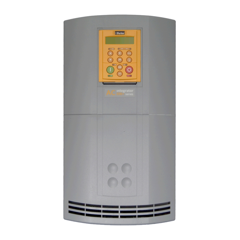
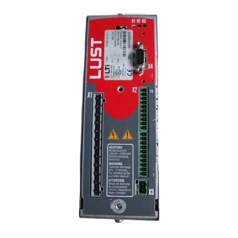
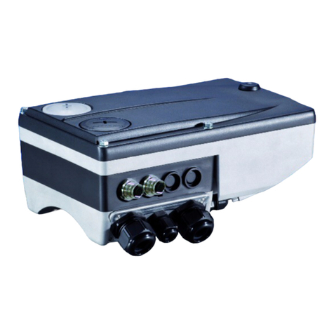
Parker 10G-11-0015 Series User manual

AC10 series
IP20 0-180kW
HA502320U001 Issue 4
Product Manual
aerospace
aerospace
climate control
climate control
electromechanical
filtration
filtration
fluid & gas handling
hydraulics
hydraulics
pneumatics
pneumatics
process control
process control
sealing & shielding
sealing & shielding
ENGINEERING YOUR SUCCESS.
www.comoso.com

www.comoso.com

AC10 series
IP20 0 – 180kW
Product Manual
HA502320U001 Issue 4
2015 Parker Hannifin Manufacturing Ltd.
All rights strictly reserved. No part of this document may be stored in a retrieval system, or transmitted in any form
or by any means to persons not employed by a Parker SSD Drives company without written permission from
Parker SSD Drives, a division of Parker Hannifin Ltd . Although every effort has been taken to ensure the accuracy
of this document it may be necessary, without notice, to make amendments or correct omissions. Parker SSD
Drives cannot accept responsibility for damage, injury, or expenses resulting therefrom.
WARRANTY
The general terms and conditions of sale of goods and/or services of Parker Hannifin Europe Sarl, Luxembourg,
Switzerland Branch, Etoy, apply to this product unless otherwise agreed. The terms and conditions are available
on our website www.parker.com/terms and conditions/switzerland
www.comoso.com

FAILURE OR IMPROPER SELECTION OR IMPROPER USE OF
THE PRODUCTS DESCRIBED HEREIN OR RELATED ITEMS
CAN CAUSE DEATH, PERSONAL INJURY AND PROPERTY
DAMAGE.
This document and other information from Parker-Hannifin
Corporation, its subsidiaries and authorized distributors provide
product or system options for further investigation by users having
technical expertise.
The user, through its own analysis and testing, is solely responsible
for making the final selection of the system and components and
assuring that all performance, endurance, maintenance, safety and
warning requirements of the application are met. The user must
analyze all aspects of the application, follow applicable industry
standards, and follow the information concerning the product in the
current product catalog and in any other materials provided from
Parker or its subsidiaries or authorized distributors.
To the extent that Parker or its subsidiaries or authorized distributors
provide component or system options based upon data or
specifications provided by the user, the user is responsible for
determining that such data and specifications are suitable and
sufficient for all applications and reasonably foreseeable uses of the
components or systems.
www.comoso.com

AC10 Inverter
Safety
Safety Information
Requirements
IMPORTANT: Please read this information BEFORE installing the equipment.
Intended Users
This manual is to be made available to all persons who are required to install, configure or
service equipment described herein, or any other associated operation.
The information given is intended to highlight safety issues, EMC considerations, and to enable
the user to obtain maximum benefit from the equipment.
Complete the following table for future reference detailing how the unit is to be installed and
used.
The information given is intended to highlight safety issues, and to enable the user to obtain
maximum benefit from the equipment.
INSTALLATION DETAILS
Model Number
(see product label)
Where installed
(for your own
information)
Unit used as a:
(refer to Certification
for the Inverter) Component Relevant Apparatus
Unit fitted: Wall-mounted Enclosure
Application Area
The equipment described is intended for industrial motor speed control utilising AC induction
motors.
Personnel
Installation, operation and maintenance of the equipment should be carried out by competent
personnel. A competent person is someone who is technically qualified and familiar with all
safety information and established safety practices; with the installation process, operation and
maintenance of this equipment; and with all the hazards involved.
Product Warnings
DANGER
Risk of electric
shock
WARNING
Hot surfaces
CAUTION
Refer to
documentation
EARTH/GROUND
Protective Conductor
Terminal
www.comoso.com

1-2 Safety
AC10 Inverter
Hazards
DANGER! - Ignoring the following may result in injury
8. This equipment can endanger life by
exposure to rotating machinery and high
voltages.
9. The equipment must be permanently
earthed due to the high earth leakage
current, and the drive motor must be
connected to an appropriate safety earth.
10. Ensure all incoming supplies are isolated
before working on the equipment. Be
aware that there may be more than one
supply connection to the drive.
11. There may still be dangerous voltages
present at power terminals (motor output,
supply input phases, DC bus and the
brake, where fitted) when the motor is at
standstill or is stopped.
12. For measurements use only a meter to
IEC 61010 (CAT III or higher). Always
begin using the highest range.
CAT I and CAT II meters must not be
used on this product.
13. Allow at least 5 minutes (20 mins for
above 30kW) for the drive's capacitors
to discharge to safe voltage levels
(<50V). Use the specified meter
capable of measuring up to 1000V dc &
ac rms to confirm that less than 50V is
present between all power terminals
and earth.
14. Unless otherwise stated, this product
must NOT be dismantled. In the event
of a fault the drive must be returned.
Refer to "Routine Maintenance and
Repair".
WARNING! - Ignoring the following may result in injury or damage to equipment
SAFETY
Where there is conflict between EMC and Safety requirements, personnel safety shall
always take precedence.
• Never perform high voltage resistance
checks on the wiring without first
disconnecting the drive from the circuit
being tested.
• Whilst ensuring ventilation is sufficient,
provide guarding and /or additional safety
systems to prevent injury or damage to
equipment.
• When replacing a drive in an application
and before returning to use, it is essential
that all user defined parameters for the
product’s operation are correctly
installed.
• The AC10 series is not a safety
component or safety related product.
• All control and signal terminals are
SELV, i.e. protected by double
insulation. Ensure all external wiring is
rated for the highest system voltage.
• Thermal sensors contained within the
motor must have at least basic
insulation.
• All exposed metalwork in the Inverter is
protected by basic insulation and
bonded to a safety earth.
• RCDs are not recommended for use
with this product but, where their use is
mandatory, only Type B RCDs should be
used.
EMC
• In a domestic environment this product
may cause radio interference in which
case supplementary mitigation measures
may be required.
• This equipment contains electrostatic
discharge (ESD) sensitive parts.
Observe static control precautions when
handling, installing and servicing this
product.
•
This is a product of the restricted sales
distribution class according to IEC
61800-3. It is designated as
“professional equipment” as defined in
EN61000-3-2. Permission of the supply
authority shall be obtained before
connection to the low voltage supply.
CAUTION!
APPLICATION RISK
• The specifications, processes and circuitry described herein are for guidance only and
may need to be adapted to the user’s specific application. We can not guarantee the
suitability of the equipment described in this Manual for individual applications.
www.comoso.com

Contents
Contents
Page
AC10 Inverter
Chapter 1 Introduction .......................................................................................................... 1-1
1.1 Understanding the Product Code ............................................................. 1-1
1.2 Nameplate Example ................................................................................. 1-1
1.3 Product Range .......................................................................................... 1-2
Chapter 2 Product Overview................................................................................................. 2-1
2.1 Designed Standards for Implementation .................................................. 2-1
2.2 Control Features ....................................................................................... 2-2
Chapter 3 Installation ............................................................................................................ 3-1
3.1 Equipment Precautions ............................................................................ 3-1
Chapter 4 Maintenance ........................................................................................................ 4-1
4.1 Periodic Checking .................................................................................... 4-1
4.2 Storage ..................................................................................................... 4-1
4.3 Daily Maintenance .................................................................................... 4-1
Chapter 5 The Keypad .......................................................................................................... 5-1
5.1 The Display .............................................................................................. 5-1
5.2 Remote-control ......................................................................................... 5-1
5.2.1 Panel Mounting Diagram .................................................................... 5-2
5.2.2 Port of control panel ............................................................................ 5-2
Chapter 6 The Menu Organisation ....................................................................................... 6-1
6.1 Parameters Setting ................................................................................... 6-1
6.2 Function Codes Switchover in/between Code-Groups ............................ 6-2
6.3 Panel Display ........................................................................................... 6-3
Chapter 7 Installation & Connection ..................................................................................... 7-1
7.1 Installation ................................................................................................ 7-1
7.2 Connection ............................................................................................... 7-3
7.3 Measurement of Main Circuit Voltages, Currents and Powers ................ 7-5
7.4 Functions of Control Terminals ................................................................. 7-7
7.5 Wiring for Digital Input Terminals: ............................................................ 7-8
7.5.1 Wiring for positive source electrode (NPN mode). ........................... 7-8
7.5.2 Wiring for active source electrode .................................................... 7-8
7.5.3 Wiring for positive Sink electrode (PNP mode) ................................ 7-8
7.5.4 Wiring for active drain electrode (PNP mode) .................................. 7-9
7.6 Connection Overview ............................................................................. 7-10
7.7 Basic methods of suppressing the noise................................................ 7-12
7.7.1 Noise propagation paths and suppressing methods ...................... 7-12
7.7.2 Basic methods of suppressing the noise ........................................ 7-13
7.7.3 Field Wire Connections .................................................................. 7-14
7.7.4 Earthing .......................................................................................... 7-14
7.7.5 Leakage Current ............................................................................. 7-15
7.7.6 Electrical Installation of the Drive ................................................... 7-15
7.7.7 Application of Power Line Filter ...................................................... 7-16
Chapter 8 Operation and Simple Running ............................................................................ 8-1
www.comoso.com

Contents
Contents
Page
AC10 Inverter
8.1 Basic Conception ..................................................................................... 8-1
8.1.1 Control Mode .................................................................................... 8-1
8.1.2 Mode of Torque Compensation ........................................................ 8-1
8.1.3 Mode of frequency setting ................................................................ 8-1
8.1.4 Mode of controlling for running command ........................................ 8-1
8.1.5 Operating status of inverter .............................................................. 8-1
8.2 Keypad Panel and Operation Method ...................................................... 8-2
8.2.1 Method of operating the keypad panel ............................................. 8-2
8.2.2 Operation Process of Setting the Parameters using the Keypad Panel
8-2
8.2.3 Setting the Parameters .................................................................... 8-2
8.2.4 Switching and displaying of status parameters ................................ 8-2
8.2.5 Switching of the parameters displayed under stopped status ......... 8-3
8.2.6 Switching of the parameters displayed under running status .......... 8-3
8.2.7 Operation process of measuring motor parameters ........................ 8-3
8.2.8 Operation process of simple running ............................................... 8-4
8.3 Illustration of Basic Operation .................................................................. 8-5
8.3.1 Frequency setting, start, forward running and stop using the keypad
panel 8-5
8.3.2 Setting the frequency using the keypad panel, and starting, forward
and reverse running, and stopping inverter through control terminals ........ 8-6
8.3.3 Operation process of jogging operation using the keypad panel ..... 8-7
8.3.4 Setting the frequency with analog terminal and controlling the
operation with control terminals ................................................................... 8-8
Chapter 9 Function Parameters ........................................................................................... 9-1
9.1 Basic Parameters ..................................................................................... 9-1
9.2 Operation Control ................................................................................... 9-10
9.3 Multifunctional Input and Output Terminals ............................................ 9-17
9.3.1 Digital multifunctional output terminals ............................................. 9-17
9.3.2 Digital multifunctional input terminals ................................................ 9-20
9.3.3 Analog input monitoring .................................................................. 9-24
9.4 Analog Input and Output ........................................................................ 9-25
9.5 Multi-stage Speed Control ...................................................................... 9-29
9.6 Auxiliary Functions ................................................................................. 9-31
9.7 Malfunction and Protection ..................................................................... 9-35
9.8 Motor Parameters ................................................................................... 9-39
9.9 Communication Parameter .................................................................... 9-42
9.10 PID Parameters .................................................................................... 9-43
9.11 Torque control parameters.................................................................... 9-46
Chapter 10 Troubleshooting ................................................................................................. 10-1
Chapter 11 Technical Specifications ..................................................................................... 11-1
11.1 Selection of Braking Resistance ............................................................ 11-1
www.comoso.com

Contents
Contents
Page
AC10 Inverter
Chapter 12 Modbus Communication .................................................................................... 12-1
12.1 General ................................................................................................. 12-1
12.2 Modbus Protocol .................................................................................. 12-1
12.2.1 Transmission mode ...................................................................... 12-1
12.2.2 ASCII Mode .................................................................................. 12-1
12.2.3 RTU Mode ................................................................................... 12-1
12.3 Baud rate .............................................................................................. 12-1
12.4 Frame structure: ................................................................................... 12-2
12.5 Error Check .......................................................................................... 12-2
12.5.1 ASCII mode .................................................................................. 12-2
12.5.2 RTU Mode .................................................................................... 12-2
12.5.3 Protocol Converter ....................................................................... 12-2
12.6 Command Type & Format .................................................................... 12-3
12.6.1 Address and meaning .................................................................. 12-3
12.6.2 Running Status Parameters ......................................................... 12-4
12.6.3 Control commands ....................................................................... 12-5
12.6.4 Illegal Response When Reading Parameters .............................. 12-6
12.7 Function Codes Related to Communication ........................................ 12-7
12.8 Physical Interface ................................................................................. 12-8
12.8.1 Interface instruction ...................................................................... 12-8
12.8.2 Structure of Field Bus ................................................................... 12-8
12.9 Grounding and Terminal ....................................................................... 12-8
12.9.1 Examples ........................................................................................ 12-9
Chapter 13 The Default Applications .................................................................................... 13-1
13.1 Application 1: Basic Speed Control ...................................................... 13-2
13.2 Application 2 : Auto/Manual Control ..................................................... 13-4
13.3 Application 3: Preset Speeds .............................................................. 13-6
13.4 Application 4 : Raise/Lower Secondary .............................................. 13-8
13.5 Application 5: PID ............................................................................... 13-10
Chapter 14 Compliance ........................................................................................................ 14-1
14.1 Applicable Standards ............................................................................ 14-1
14.2 European Compliance .......................................................................... 14-2
14.2.1 Low Voltage Directive...................................................................... 14-2
14.2.2 EMC Directive ................................................................................. 14-2
14.2.3 Machinery Directive......................................................................... 14-2
14.2.4 EMC Compliance ............................................................................ 14-2
14.3 EMC Standards Comparison .................................................................. 14-3
14.3.1 Radiated .......................................................................................... 14-3
14.4 North American & Canadian Compliance Information (Frame 1 – 5 ONLY)
14-5
14.4.1 UL Standards ................................................................................ 14-5
14.4.2 UL Standards Compliance ............................................................ 14-5
www.comoso.com

Contents
Contents
Page
AC10 Inverter
Chapter 15 Parameter Reference ........................................................................................ 15-1
15.1 Basic parameters: F100-F160 .............................................................. 15-1
15.2 Running control mode: F200-F230 ...................................................... 15-4
15.3 Multifunctional Input and Output Terminals: F300-F330 ...................... 15-6
15.4 Analog Input and Output: F400-F480................................................... 15-8
15.5 Multi-stage Speed Control: F500-F580 .............................................. 15-10
15.6 Auxiliary Functions: F600-F670 .......................................................... 15-11
15.7 Timing Control and Protection: F700-F770 ........................................ 15-12
15.8 Motor parameters: F800-F830 ........................................................... 15-14
15.9 PID parameters: FA00-FA80 .............................................................. 15-16
15.10 Torque control parameters: FC00-FC40 .......................................... 15-17
www.comoso.com

Introduction 1-1
AC10 Inverter
Chapter 1 Introduction
This manual offers an introduction to the installation and connection for the AC10 series.
Parameters setting, software and operations are also covered in this manual.
1.1 Understanding the Product Code
Model Number
The unit is fully identified using a four block alphanumeric code which records how the drive
was calibrated, and its various settings when dispatched from the factory. This can also be
referred to as the Product Code.
Input voltage:
1 : 1 Phase 230V/240V
2 : 3 Phase 230V/240V
4 : 3 Phase 380V/480V
Industry
Rated current (A):
XXXX OOO.O
Product model
Frame Size: (mm)
1:
2:
3:
4:
5:
F : Built in filter
N : without built in filter
10 G - 1 1 - 0015-B F
B: Built -in braking unit
80×135×138
106×150×180
138×152×235
156×170×265
205×196×340
6:
7:
8:
9:
10:
265×235×435
315×234×480
360×265×555
410×300×630
516×326×765
--
11:
560×342×910
1.2 Nameplate Example
This example nameplate shows the product as an AC10 series 3.7kW inverter with 3-phase
input. (UL pending).
3Ph: three-phase input; 380-480V, 50/60Hz: input voltage range and rated frequency.
3Ph: 3-phase output; 8.0A, 3.7kW: rated output current and power;
www.comoso.com

1-2 Introduction
AC10 Inverter
1.3 Product Range
Supply Part number kW Input current (A) Output
Current (A) Input
protection
current
230V 380V/400V 460V/480V
1Ph 230V
10G-11-0015-XX
0.2
4
1.5
6.0
10G-11-0025-XX
0.37
5.8
2.5
10.0
10G-11-0035-XX
0.55
7.6
3.5
14.0
10G-11-0045-XX
0.75
10
4.5
18.1
10G-12-0050-XX
1.1
10.8
5
24.5
10G-12-0070-XX
1.5
14
7
25.2
10G-12-0100-XX
2.2
20
10
32.0
3Ph 230V
10G-31-0015-XX
0.2
2.5
1.5
5.0
10G-31-0025-XX
0.37
3.5
2.5
8.2
10G-31-0035-XX
0.55
4.5
3.5
10.0
10G-31-0045-XX
0.75
5.4
4.5
11.5
10G-32-0050-XX
1.1
5.8
5
18.0
10G-32-0070-XX
1.5
7.8
7
18.2
10G-32-0100-XX
2.2
11
10
21.5
3Ph 400V
10G-41-0006-XX
0.2
1.1
0.8
0.6
2.5
10G-41-0010-XX
0.37
1.5
1.2
1
5.0
10G-41-0015-XX
0.55
2.1
1.8
1.5
5.5
10G-42-0020-XX
0.75
3
2.1
2
6.5
10G-42-0030-XX
1.1
4
3.2
3
10.2
10G-42-0040-XX
1.5
5
4.2
4
11.0
10G-42-0065-XX
2.2
7.5
7.0
6.5
15.0
10G-43-0080-XX
3.7
10.5
8.3
8
18.0
10G-43-0090-XX
4
11
9.2
9
21.0
10G-43-0120-XX
5.5
14
11.5
12
29.0
10G-44-0170-XX
7.5
18.5
16
17
34.0
10G-44-0230-XX
11
24
21
23
46.5
10G-45-0320-XX
15
36.5
27
32
80.0
10G-45-0380-XX
18.5
44
31
38
90
10G-45-0440-XX
22
51
35
44
100
10G-46-0600-XX
30
70
53
60
110
10G-47-0750-XX
37
80
64
75
120
10G-47-0900-XX
45
94
75
90
150
10G-48-1100-XX
55
120
85
110
180
10G-48-1500-XX
75
160
115
150
240
10G-49-1800-XX
90
190
130
180
285
10G-49-2200-XX
110
225
170
220
340
10G-410-2650-XX
132
275
210
265
400
10G-411-3200-XX
160
330
250
320
500
10G-411-3600-XX
180
370
280
360
550
www.comoso.com

Product Overview 2-1
AC10 Inverter
Chapter 2 Product Overview
The external structure of AC10 series inverter has a plastic housing.
Illustrated is the AC10G-12-0050-XX
Metal housing uses advanced exterior plastic- spraying and powder-spraying process on the
surface with color and detachable one-side door hinge structure adopted for front cover,
convenient for wiring and maintenance. Taking 10G-46-0060 for instance, its appearance and
structure are shown below.
2.1 Designed Standards for Implementation
IEC/EN 61800-5-1: 2007 Adjustable speed electrical power drive systems safety requirements.
IEC/EN 61800-3: 2004 Adjustable speed electrical power drive systems-Part 3: EMC product
standard including specific test methods.
Heatsink
www.comoso.com

2-2 Product Overview
AC10 Inverter
2.2 Control Features
Table 2-1 Technical Specification for AC10 series Inverters
Input Rated Voltage Range
3-phase 380-480V (+10%, -15%)
1-phase 220-240V ±15%
3-phase 220-240V ±15%
Rated Frequency
50/60Hz
Output
Rated Voltage Range
3-phase 0-INPUT (V)
Frequency Range 0.50~590.0Hz
Control Mode
Carrier Frequency
800~10000Hz; Fixed carrier-wave and random carrier-wave
can be selected by F159.
Input Frequency Resolution
Digital setting: 0.01Hz, analog setting: max frequency
×
0.1%
Control Mode
Sensorless vector control (SVC), V/Hz control
Start Torque
0.5 Hz / 150% (SVC)
Speed-control Scope
1:100 (SVC)
Steady Speed Precision
±0.5%
(
SVC
)
Torque Control Precision
±5%
(
SVC
)
Overload Capacity
150% rated current, 60 seconds.
Torque Elevating
Auto torque promotion, manual torque promotion
includes 1-20 curves.
VVVF Curve
3 kinds of modes: quadratic type, square type and
user-defined V/Hz curve.
DC Braking
DC braking frequency: 0.2-5.00 Hz, braking time:
0.00~30.00s
Jogging Control
Jogging frequency range: min frequency~ max
frequency, jogging acceleration/deceleration time:
0.1~3000.0s
Auto Circulating Running
and multi-stage speed
running
Auto circulating running or terminals control can realize
15-stage speed running.
Built-in PID adjusting
Easy to realize a system for process closed-loop control
Auto voltage regulation
(AVR)
When source voltage changes, the modulation rate can
be adjusted automatically, so that the output voltage is
unchanged.
Operation Function
Frequency Setting
Analog signal (0
~
5V, 0
~
10V, 0
~
20mA); keypad
(terminal)▲/▼ keys, external control logic and
automatic circulation setting.
Start/Stop Control
Terminal control, keypad control or communication
control.
Running Command
Channels
3 kinds of channels from keypad panel, control terminals
or RS485
Frequency Source
Frequency sources: User terminals, from the MMI or via
RS485.
Auxiliary frequency Source
5 options
Optional
Built-in EMC filter, built-in braking unit
Protection Function
Input phase loss, Output phase loss, input under-voltage, DC over-voltage,
over-current, inverter over-load, motor over-load, current stall, over-heat, external
disturbance, analog line disconnected.
MMI
Display
LED seven segment display showing output frequency, rotate-speed (rpm), output
current, output voltage, DC bus voltage, PID feedback value, PID setting value,
linear-velocity, types of faults, and parameters for the system and operation; LED
indicators showing the current working status of inverter.
Environment
Conditions
Equipment Location
In an indoor location, Prevent exposure from direct
sunlight, from dust, from caustic gases, flammable
gases, steam or other contamination.
Environment Temperature
-10oC
~
+40oC (50oC with derating)
Environment Humidity
Below 90% (non condensing)
Vibration Strength
Below 0.5g
Height above sea level
1000m or below (3000m with derating)
Environment
3C3 conformance
Protection level
IP20
Applicable Motor 0.2~180kW
www.comoso.com

Installation 3-1
AC10 Inverter
Chapter 3 Installation
IMPORTANT Read Chapter 14 “Compliance” before installing this unit.
3.1 Equipment Precautions
• Check for signs of transit damage.
• Check the product code on the rating label conforms to your requirements.
• Installation and application environment should be free of rain, drips, steam, dust and oily
dirt; without corrosive or flammable gases or liquids, metal particles or metal powder.
Environment temperature within the scope of -10℃~+50℃(40℃ without derating)
• Please install inverter away from combustibles.
• Do not drop anything into the inverter.
• The reliability of inverters relies heavily on the temperature. As the surrounding
temperature increases by 10 degrees the inverter life will be halved.
• The inverter is designed to be installed in a control cabinet, smooth ventilation should be
ensured and the inverter should be installed vertically. If there are several inverters in one
cabinet, in order to ensure ventilation, install inverters side by side. If it is necessary to
install several inverters above each other, you need additional ventilation.
• Never touch the internal elements for 15 minutes after power goes off. Wait until it is
completely discharged.
• Input terminals R, S and T are connected to power supply of 230V/400V while output
terminals U, V and W are connected to motor.
• Proper grounding should be ensured. Separate grounding is required for motor and
inverter. Grounding with series connection is forbidden.
• There should be separate wiring between control loop and power loop to avoid any
possible interference.
• Cable length should be minimized to limit common mode interference.
• If circuit breaker or contactor needs to be connected between the drive and the motor, be
sure to operate these circuit breakers or contactor when the drive has no output, to avoid
damaging the drive.
• Before using the drive, the insulation of the motors must be checked, especially if it is used for
the first time or if it has been stored for a long time. This is to reduce the risk of the drive being
damaged by poor insulation of the motor.
• Do not connect any varistor or capacitor to the output terminals of the drive because the drive’s
output voltage waveform is pulse wave, otherwise tripping or damaging of components may
occur.
www.comoso.com

3-2 Installation
AC10 Inverter
Inverter
M
Figure 3-1 Capacitors are prohibited to be used
• Derating must be considered when the drive is installed at high altitude (greater than
1000m). This is because the cooling effect of drive is deteriorated due to the thin air, as
shown in Figure 3-2 that indicates the relationship between the elevation and rated
current of the drive.
Figure 3-2 Derating drive’s output current with altitude
Temperature derating
0.2 0.37 0.55 0.75 1.1 1.5 2.2 3.7 45.5 7.5 11 15 18.5 22 30 37 45 55 75 90 110 132 160 180
0.2 40 C 50 C 50 C 50 C 50 C 50 C 50 C 50 C 50 C 50 C 50 C 50 C 50 C 50 C 50 C 50 C 50 C 50 C 50 C 50 C 50 C 50 C 50 C 50 C 50 C
0.37 30 C 40 C 50 C 50 C 50 C 50 C 50 C 50 C 50 C 50 C 50 C 50 C 50 C 50 C 50 C 50 C 50 C 50 C 50 C 50 C 50 C 50 C 50 C 50 C 50 C
0.55 20 C 30 C 40 C 50 C 50 C 50 C 50 C 50 C 50 C 50 C 50 C 50 C 50 C 50 C 50 C 50 C 50 C 50 C 50 C 50 C 50 C 50 C 50 C 50 C 50 C
0.75 20 C 30 C 40 C 45 C 50 C 50 C 50 C 50 C 50 C 50 C 50 C 50 C 50 C 50 C 50 C 50 C 50 C 50 C 50 C 50 C 50 C 50 C 50 C 50 C
1.1 30 C 40 C 45 C 50 C 50 C 50 C 50 C 50 C 50 C 50 C 50 C 50 C 50 C 50 C 50 C 50 C 50 C 50 C 50 C 50 C 50 C 50 C
1.5 30 C 40 C 50 C 50 C 50 C 50 C 50 C 50 C 50 C 50 C 50 C 50 C 50 C 50 C 50 C 50 C 50 C 50 C 50 C 50 C 50 C
2.2 35 C 40 C 50 C 50 C 50 C 50 C 50 C 50 C 50 C 50 C 50 C 50 C 50 C 50 C 50 C 50 C 50 C 50 C 50 C 50 C
3.7 25 C 40 C 50 C 50 C 50 C 50 C 50 C 50 C 50 C 50 C 50 C 50 C 50 C 50 C 50 C 50 C 50 C 50 C 50 C
430 C 40 C 50 C 50 C 50 C 50 C 50 C 50 C 50 C 50 C 50 C 50 C 50 C 50 C 50 C 50 C 50 C 50 C
5.5 30 C 40 C 50 C 50 C 50 C 50 C 50 C 50 C 50 C 50 C 50 C 50 C 50 C 50 C 50 C 50 C 50 C
7.5 25 C 40 C 50 C 50 C 50 C 50 C 50 C 50 C 50 C 50 C 50 C 50 C 50 C 50 C 50 C 50 C
11 20 C 40 C 50 C 50 C 50 C 50 C 50 C 50 C 50 C 50 C 50 C 50 C 50 C 50 C 50 C
15 20 C 40 C 50 C 50 C 50 C 50 C 50 C 50 C 50 C 50 C 50 C 50 C 50 C 50 C
18.5 20 C 40 C 50 C 50 C 50 C 50 C 50 C 50 C 50 C 50 C 50 C 50 C 50 C
22 20 C 40 C 50 C 50 C 50 C 50 C 50 C 50 C 50 C 50 C 50 C 50 C
30 20 C 40 C 50 C 50 C 50 C 50 C 50 C 50 C 50 C 50 C 50 C
37 20 C 40 C 50 C 50 C 50 C 50 C 50 C 50 C 50 C 50 C
45 20 C 40 C 50 C 50 C 50 C 50 C 50 C 50 C 50 C
55 20 C 40 C 50 C 50 C 50 C 50 C 50 C 50 C
75 20 C 40 C 50 C 50 C 50 C 50 C 50 C
90 20 C 40 C 50 C 50 C 50 C 50 C
110 20 C 40 C 50 C 50 C 50 C
132 20 C 40 C 50 C 50 C
160 20 C 40 C 50 C
180 20 C 40 C
Power of Motor (kW)
Power of drive (kW)
Iout
(m
)
100%
90%
80%
1000 2000 3000
www.comoso.com

Maintenance 4-1
AC10 Inverter
Chapter 4 Maintenance
4.1 Periodic Checking
Cooling fan and ventilation channel should be cleaned regularly to check it is clear; remove any
dust accumulated in the inverter on a regular basis.
Check inverter’s input and output wiring and wiring terminals regularly and check if wirings are
ageing.
Check whether screws on each terminals are fastened.
4.2 Storage
Please put the inverter in the packing case of manufacture.
If inverter is stored for long time, charge the inverter within half a year to prevent the electrolytic
capacitors being damaged. The charging time should be longer than 5 hours.
4.3 Daily Maintenance
Environment temperature, humidity, dust and vibration would decrease the life of inverter. Daily
maintenance is necessary to inverters.
Daily inspecting:
Inspecting for noise of motor when it is working.
Inspecting for abnormal vibration of motor when it is working.
Inspecting for the installing environment of inverter.
Inspecting for the fan and inverter temperature.
Daily cleaning:
Keep the inverter clean. Clean surface dust of inverter to prevent dust, metal powder, oily dirt
and water from dropping into the inverter.
www.comoso.com

5-1 The Keypad
AC10 Inverter
Chapter 5 The Keypad
5.1 The Display
The panel covers three sections: data display section, status indicating section and keypad
operating section, as shown in Figure 5-1.
Figure 5-1 Keypad Display
5.2 Remote-control
The remote mounted keypad can be ordered as 1001-00-00.
This includes the keypad, cable and mounting brackets.
Layout diagram
Keypad Measurements (Unit:mm)
Code
A
B
C
D
H
Opening size
1001-00-00
124
74
120
70
26
121*71
4 LEDs indicate working status. RUN while running. FWD running
forward and FRQ when the MMI is showing frequency.
LED shows running frequency, flashing target frequency,
function code, parameter value or fault code.
Press “M” for function code, and “E” for original
parameters.
▲and▼keys can be used to select function
codes and parameters. Press
“E” again to confirm. In the
mode of keypad control,
▲and▼key
s can also be used for
dynamic speed control.
“I” and “O” keys control start and
stop. Press
“O” key to reset inverter in fault status.
www.comoso.com

The Keypad 5-2
AC10 Inverter
5.2.1 Panel Mounting Diagram
Mounting panel
Keypad frame
Frame back cover
Panel mounting size (Unit: mm)
Code Keypad panel size Opening size
E
F
L
N
M
1001-00-00
170
110
22
102
142
5.2.2 Port of control panel
Pins
1
2
3
4
5
6
7
8
8 core
None
5V
Grounding
Grounding
Signal
1
Signal
2
Signal
3
Signal
4
The default length of remote cable is 1m. On the occasion of heavy interference or if remote
control cable is longer than 3m, please add magnetic ring on the cable.
www.comoso.com

6-1 The Menu Organisation
AC10 Inverter
Chapter 6 The Menu Organisation
All keys on the panel are available for user. Refer to Table 6-1 for their functions.
Table 6-1 Uses of Keys
Keys
Names
Remarks
Menu To call function code and switch over display mode.
Enter To call and save data.
Up To increase data (speed control or setting parameters)
Down To decrease data (speed control or setting parameters)
Run To start inverter
Stop or
Reset
To stop inverter; to reset in fault status; to change function codes in a
code group or between two code groups. In the interface of
function code, keep pressing “O” key for 3s, inverter will be stopped.
(if stop command is controlled by keypad).
6.1 Parameters Setting
This inverter has numerous function parameters that the user can modify to effect different
modes of operation. The user should be aware that if they set password valid (F107=1), the
password must be entered first.
Table 6-2 Steps for Parameters Setting
Steps Keys Operation Display
1 Press “M” key to display function code
2 Press “Up” or “Down” to select required function code
3 Read data set in the function code
4 To modify data
5
Shows corresponding target frequency by flashing
after saving the set data
Displays the current function code
The above-mentioned step should be operated when inverter is in stop status.
M
E
I
O
▲
▼
M
▲
▼
or
E
M
E
▲
▼
or
www.comoso.com
Other manuals for 10G-11-0015 Series
1
This manual suits for next models
38
Table of contents
Other Parker Inverter Drive manuals