Partner K950 RING Instruction manual

Workshop
Manual
PARTNER
K950 RING

1. LITERATURE 1
2. BASIC FUNCTION 2
3. COMPONENTS – ORIENTATION 3
4. REPLACEMENT OF CUTTER BLADE 4
5. ROLLERS – ADJUSTMENT/INSPECTION 6
6. ENGAGEMENT AND SUPPORT ROLLERS 7
7. REPLACEMENT OF ENGAGEMENT AND
SUPPORT ROLLERS 8
8. REPLACEMENT OF THE ROLLERS’ BEARINGS 11
9. REPLACEMENT OF ENGAGEMENT ROLLERS’
BEARING SLEEVE 14
10. REPLACEMENT OF DRIVE DISC BEARING 15
CONTENTS Page
PARTNER
K950 RING
108 89 37-26

1
LITERATURE 1
Workshop manuals
A complete manual for service and repair of
the Partner K950 Ring consists of two work-
shop handbooks.
Workshop manual K950 RING
This encompasses measures that are specific
to the K950 Ring, such as servicing of the
blade’s drive and control systems.
Workshop manual POWER CUTTERS
This covers measures that are the same for
the centre-driven K950 Active and the K950
Ring, such as the engine unit.
This manual also deals with most of the
petrol-powered cutting machines that fea-
ture a centre-driven blade.
Structure – text and illustrations
This manual is divided into chapters, with
chapter numbers printed at the top of each
page.
In addition to photographs and drawings,
there are usually two columns of text. The
column on the left is brief and is intended
for the experienced mechanic, while the
column on the right is more detailed and is
aimed at the mechanic with less experience
of power cutters.
Spare parts
Spare parts, K950 RING
This folder covers all the spare parts for the
Partner K950 Ring.
The folder includes comprehensive skele-
ton drawings of the entire machine, allo-
wing convenient and clear identification of
each component’s position, part number
and appearance.
PARTNER
Workshop
Manual
PARTNER
Workshop
Manual
K950 RING
108 89 37-26

BASIC FUNCTION2
The blade’s drive and control
systems
Eccentric drive
The unique concept behind the K950 Ring is its
eccentric drive (outside the centre) and control of
the cutter blade (A).
Function
The drive disc (B) which is powered by a belt dri-
ven off the engine, has a groove into which the
blade slots.
The two engagement rollers (C) exert pressure
against the blade (from the engagement roller
springs, when the knob is tightened), causing the
blade to press against the drive disc. The lower
picture shows how the engagement roller flanges
grip in the cutter blade’s groove. The only function
of the support roller (D) is to exert counter-pressu-
re so that the blade is located properly against the
rollers without any play or clearance.
With this design, the cutter blade can be con-
trolled in both the radial and axial directions (rota-
ting and lateral movements). Three points (at the
two engagement and support rollers and at the
drive disc) guide the blade at the same time as the
pressure against the drive disc generates sufficient
friction to drive the blade.
Important for good function
The description of the function indicates that it is
particularly important that the engagement rollers
can move axially without interference from the
spring force (the direction of the arrows), so as to
provide the correct pressure against the drive disc.
Corrosion or dirt that blocks movement will cause
the blade to slip against the drive disc. A properly
greased bearing housing will reduce the risk of
operational disruption.
Wear
In comparison with a traditional centre-driven
machine, the blade’s drive and engagement
systems are subjected to harder wear since the
mechanical parts work constantly in an environ-
ment of water and slurry.
Parts subject to wear
The wear-prone parts are the drive discs, engage-
ment rollers and support rollers (B, C and D in the
figure). These parts can be quickly and easily re-
placed and this job is normally carried out by the
user.
(The machine comes with a video that provides a
detailed description of the service measures that
the user should carry out.)
IMPORTANT
In all control and adjustment work on the engage-
ment and support rollers, the knob that tensions
the blade against the drive disc must be unscrewed
to its end position. Make a habit of starting off
each shift by unscrewing the knob and finish-
ing your shift by screwing it back in!
2
A
B
B
C
CD
C
A
A
B
DC
108 89 37-26

3
COMPONENTS – ORIENTATION 3
Components
1. Cutter blade, ring-shaped steel
blade with laser-welded diamond
tips
2. Engagement rollers (behind the
shroud)
3. Blade guard
4. Splash guard
5. Hose for water supply
6. Control for adjustment of water
flow
7. Water disc
8. Lock button for disc drive
9. Knob tensioning the blade
against the drive disc
10 Support roller cover
11 Support rollers (behind the
shroud)
12. Adjustment screws for roller
tension against the blade
13. Lock-nuts for roller adjustment
14 Drive disc (behind the shroud)
15 Transmission cover
16 Grease nipples for lubrication of
the bearing housings
17 Lubrication duct outlets
NOTE
Compared with the hydraulic ring
cutter, the Partner K3600, the
engagement and support rollers have
switched places in the K950 Ring.
The blade’s direction of rotation in
relation to the machine is the same
for both machines (dragging blade),
but the blade itself rotates in the
opposite direction.
For this reason, it is important not
to confuse the blades used in these
two machines. Switching between
the direction of rotation causes
added blade wear.
1
2
4
8
5
69
9
10
211
14
12
11
11
12 13
13
15
7
2
3
12
13
1716
New version
Grease nipples (16) and lubrication ducts
have been engineered into the bearing
housings. The exit holes (17) indicate when
the correct amount of grease has been
filled.

REPLACEMENT OF CUTTER BLADE
Removal
Unscrew the knob to its end
position.
Unscrew the adjustment
screws (A) at least two turns.
Undo the lock-nuts (B).
Removal
First unscrew the two knobs to their
end positions – the drive disc now
applies no tension at all on the
blade.
Unscrew the adjustment screws (A) at
least two turns.
Undo the lock-nuts (B) for the sup-
port rollers.
4
Remove the shroud
Undo the four hex-head
screws.
Remove the support roller shroud
The support roller shroud is secured
with four hex-head screws. Undo
them.
Lift out the blade
Lift off the shroud.
Remove the blade.
Lift out the blade.
Lift off the shroud.
Lift off the blade from the engage-
ment rollers and take the blade out
of the drive disc’s groove. Remove
the blade.
Inspection
The rollers’ bearings
Check that the engagement
and support rollers rotate
easily.
For bearing replacement, see
chapter 8.
Inspection
Check at blade replacement
In connection with blade replace-
ment, it is a good idea and an easy
operation to carry out a quick check
of the condition of the engagement
and support rollers.
The rollers’ bearings
Check by hand to feel whether the
rollers rotate easily and smoothly. If
the bearings are damaged, this must
be rectified, see chapter 8.
Flange and waist
Check the rollers’ flange and
waist respectively. Replace if
necessary. See chapters 6 and
7.
Bearing housing – engage-
ment rollers
Check that the bearing hous-
ings do not stick axially.
Flange and waist
Check also that the engagement rol-
ler’s flange and the support roller’s
waist (circled) are within the stated
tolerances, see chapter 6. If necessary,
replace the engagement and support
rollers as per chapter 7.
Bearing housing – engagement
rollers
Check that the bearing housings do
not stick:
Previous model: press in the disc by
hand.
New model: tighten the knob about
one turn and check that the bearing
housings move.
A
B
4

5
REPLACEMENT OF CUTTER BLADE
Replacement of drive disc
Blade and drive disc replaced together
A new blade is always fitted together with a new driver disc. When
fitting an already used blade, its respective drive disc should also be
fitted.
A used blade may be run together with a new drive disc, but a new
blade may never be run together with a used drive disc.
Remove the drive disc
Press in the rotation catch.
Remove the centre screw, lift
out the washer and drive
disc.
Fit new drive disc
Remove the drive disc
Press in the drive disc’s rotation catch,
which is found on the underside of
the transmission shroud.
Remove the centre screw, lift out the
washer and drive disc.
Fit new drive disc
Fit the new drive disc. Keep the
rotation catch pressed and pull hard
on the centre screw.
Fit the blade
Fit according to 1, 2, 3 below.
Fit the blade
The knob should be unscrewed all
the way to its end position. Fit accor-
ding to 1, 2, 3 below.
Check the position of the adjust-
ment screws
Fit the shroud and tighten the screws
lightly. Check that the adjustment
screws are sufficiently unscrewed, as
follows: rotate the blade by hand –
the discs should not rotate or should
be easily able to be stopped. If not,
unscrew the adjustment screws.
Now tighten the shroud’s screws
firmly.
Adjust disc pressure
Before the machine is used, the discs
must first be adjusted as in chapter 5
1. Align the cutter blade with the drive
disc.
2. Align the groove in the blade with
the upper engagement roller.
3. Press in the lower engagement roller
with one hand at the same time as the
blade slips into the engagement roller.
In the new version with the pre-
tensioned springs in the bearing housing,
the disc does not need to be pressed in.
Check the position of the
adjustment screws
Fit the shroud and tighten the
screws lightly. Rotate the
blade by hand – the discs
should not rotate or should be
easily able to be stopped. If
not, unscrew the adjustment
screws.
Now tighten the shroud’s
screws firmly.
Adjust disc pressure
Adjust as in chapter 5.
!
4

ROLLERS – ADJUSTMENT/INSPECTION5
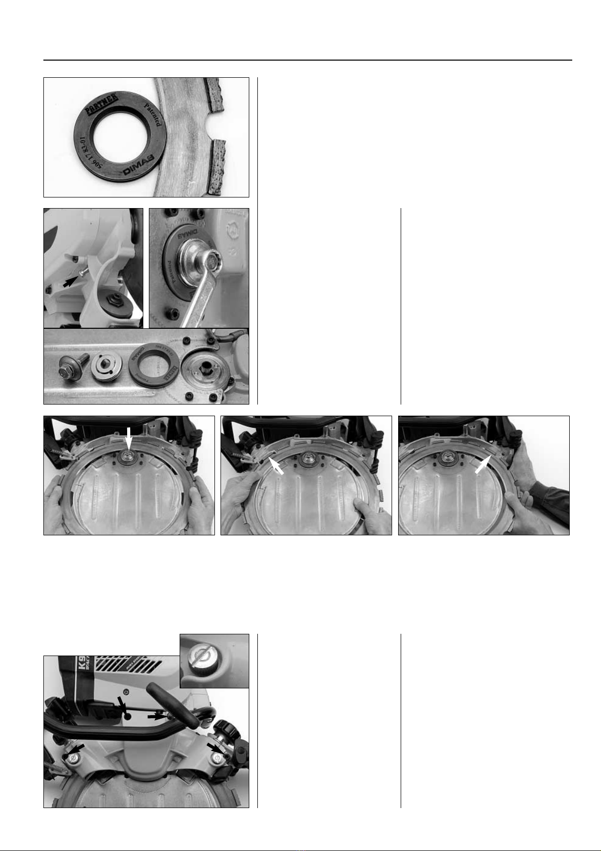
Adjustment
Important – knob unscrewed
The knob should be un-
screwed to its end position.
Undo the lock-nuts
Rough adjustment
Rotate the blade by hand
and tighten the adjustment
screws until the rollers rotate
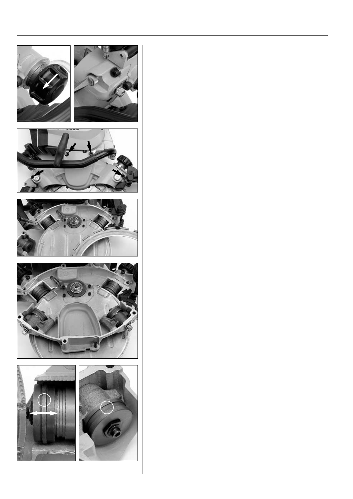
Fine adjustment
Fine-tune the adjustment to
a position where you can
easily stop the rotation of
the rollers using your thumb
(lower picture).
Tighten the lock-nuts –
final check
Tighten the lock-nuts firmly
and carry out a final check of
the adjustments.
Tighten the knob
Adjustment
Important – knob unscrewed
Roller adjustment should always be
performed with the knob unscrewed
to its end position. Undo the lock-
nuts.
The best adjustment check is obtai-
ned if the lock-nuts are tightened
somewhat before adjustment is
carried out.
Rough adjustment
Rotate the blade by hand and tighten
the adjustment screws until the rol-
lers rotate.
Fine adjustment
Fine-tune the adjustment to a posi-
tion where you can easily stop the
rotation of the rollers using your
thumb (lower picture).
Tighten the lock-nuts – final check
Tighten the lock-nuts firmly and carry
out a final check of the adjustments.
Tighten the knob
End by tightening the knob that ten-
sions the blade against the drive disc.
Correct adjustment
Correctly adjusted rollers are very important to
the machine’s function and in order to reduce
wear.
Correct adjustment means that the rollers
should be in uniform contact with the blade
without any play or clearance.
If the rollers fit too tightly, the result is in-
creased wear and blade deformation, which
can even lead to blade breakage.
If the rollers are not fitted tightly enough,
the blade is not guided properly, which in the
worst-case scenario can lead to the blade jum-
ping out of its groove.
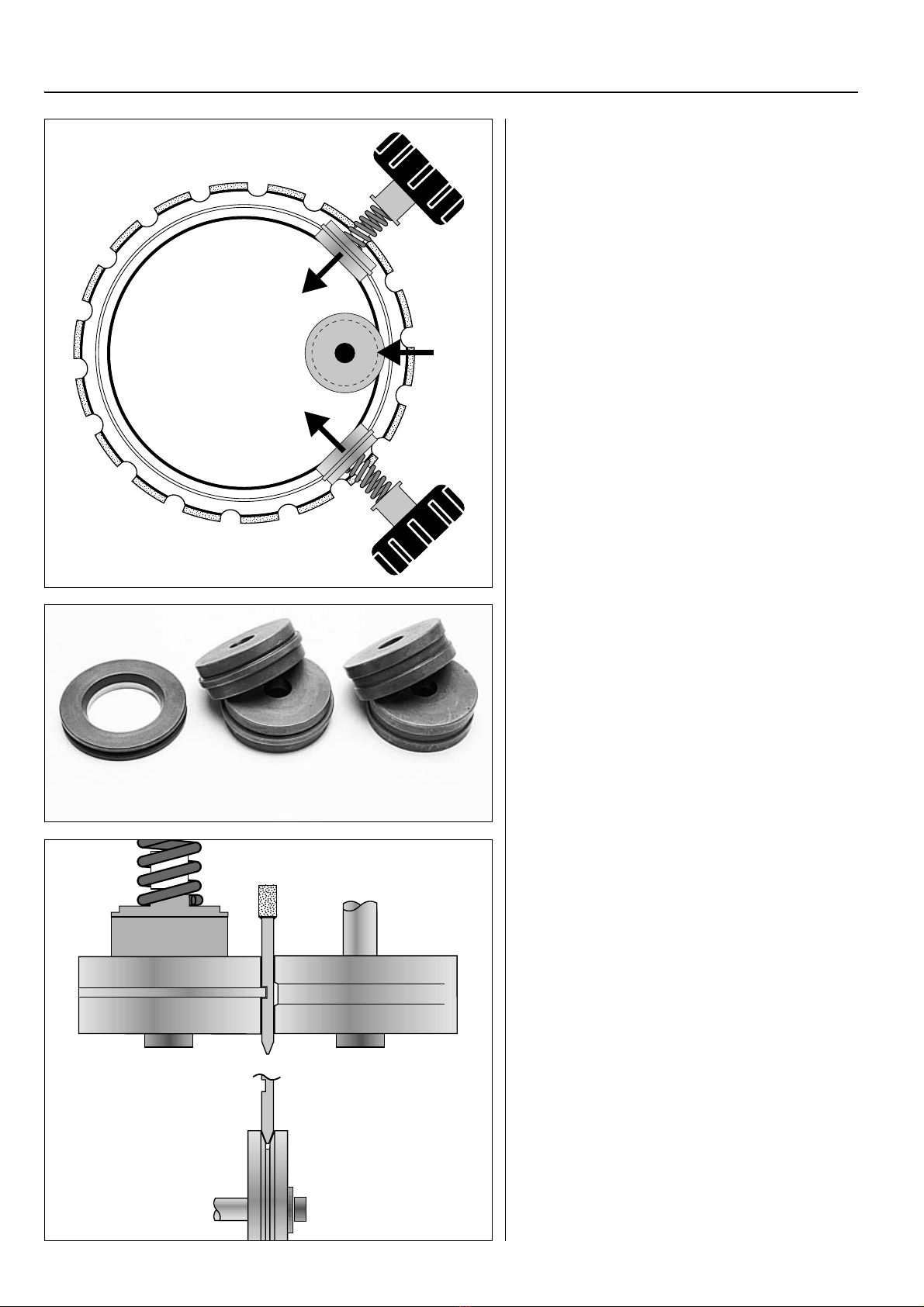
Function
The support rollers are fitted on levers in the
support roller shroud. The adjustment screws
(A) are used to alter the position of the lever.
The lock-nuts (B) lock the lever in position.
6
The rollers must always be adjusted when:
– switching to a new blade
– switching to another used blade
– replacing engagement or support rollers
Always check adjustment when the support roller shroud has
been removed and refitted.
A
A
A
AB
B
B
Inspection
At least once during the
blade’s lifetime
This check is carried out in
the same way as described
above.
Do not forget that the
knob must be unscrewed to
its end position when perfor-
ming the check!
Inspection
At least once during the blade’s
lifetime
This check is carried out in the same
way as described above.
Do not forget that the knob must
be unscrewed to its end position
when performing the check! If the
pressure is incorrect, undo the lock-
nut and adjust properly. Tighten the
lock-nut securely, carry out a final
check and end by tightening the
knob to its end position.

7
ENGAGEMENT AND SUPPORT ROLLERS 6
The drive disc and the engagement
and support rollers are subjected to
considerable wear owing to the slurry
in which they have to operate. These
wear-prone parts are therefore
designed for easy replacement. The
service life of a set of engagement
and support rollers may vary consider-
ably depending on the material
being cut and the cutting technique
used. If insufficient water is used
during cutting, the rate of wear
increases. A set of rollers usually lasts
for about 2 to 6 blades.
The same disc/roller type is repla-
ced in pairs
In order for the blade to sit straight
in the drive disc, the same roller type
must always be replaced in pairs.
Upper and lower rollers can
switch places
It is normal for the upper engage-
ment roller’s flange to wear more
quickly owing to the feed pressure’s
extra load on this disc. It is OK to
switch the positions of the upper and
lower discs to exploit the entire ser-
vice lifetime of both discs before
replacement.
Wear limit
Engagement rollers
The engagement rollers must have a
flange width of at least .06 in./1.5 mm.
Support rollers
The support rollers must be replaced
when the rollers no longer have a
waist.
Min. 1.5 mm
0.06 in.
Older model
The older model is recognisable by its
stop screws (A). The stop screws limit
the movement of the knob at its
extended position and must be re-
moved in order to extract the knob
and press out the bearing housing.
New model
In the new version, the spring and
stroke limiter are enclosed in the
bearing housing. The knob has a
distinct stop position when it is un-
screwed for adjustment of the rollers.
The new model has a grease nipple
(B) and lubrication ducts in the bea-
ring housing. An outlet duct (C)
shows when the correct amount of
grease has been filled.
Knob with snap-in fastener
The new knob has a snap-in fastener
that engages with the bearing hous-
ing’s pin. By unscrewing the knob,
the snap-in fastener disengages from
the pin and the bearing housing can
be pulled out.
Engagement rollers – model variants
A
A
B
C
0.44 in.
11 mm
Conversion
The older model can be converted to
conform to the newer standard. The
following parts have to be replaced:
bearing sleeves, bearing housing and
knob.
A grease nipple has to be added.
Drill a hole as in the illustration, dia-
meter 5.0 mm and thread M6. Fit the
grease nipple. The hole for the stop
screw is left open.
2
Replaceable consumables

REPLACEMENT OF ENGAGEMENT AND SUPPORT ROLLERS
Engagement rollers
Remove the complete en-
gagement roller unit (bea-
ring housing with fitted
engagement roller).
Old model
Remove the stop screws (A).
Remove the knob (B).
New model
Unscrew the knob.
Engagement rollers
Remove the support roller shroud
and the blade.
When replacing the engagement
roller, the complete bearing housing
is taken out for inspection and ser-
vice.
Old model
Remove the stop screws (A). Remove
the knob (B).
New model
Force the knob off the snap-in faste-
ner by unscrewing the knob past the
end position. Unscrew the knob (B).
8
Replacement of engage-
ment rollers
Tension the tool in a vice
The easiest way to remove the worn
part is to secure a box spanner in a
vice. Lock the nut using the box
spanner and unscrew the hex-head
screw.
Never put the roller in the vice!
Inspection, cleaning
Pull or push out the bearing housing.
A defective bearing housing
(wear/corrosion) is most conveniently
replaced with a new bearing housing
complete with bearings.
Bearings are replaced as per chap-
ter 8.
Clean the bearing housing from all
traces of old grease.
Wipe the bearing housing clean and
dry and check that it is undamaged.
Check that the engagement roller’s
bearings are in good condition.
Grease – properties
The grease used in the following
service measures should be of a
thick type that offers good
resistance to water penetration.
The grease used by the factory
during assembly is Shell Alvania
RL3 (lithium grease), where the
figure 3 indicates the grease’s
NLGI rating.
If other brands are used, grease
with a corresponding NLGI rating
should be used.
(The NLGI rating indicates the
grease’s stiffness, with a high
rating indicating stiff grease.)
Worn-out engagement rollers and sup-
port rollers have a smaller diameter
than their new counterparts. Unscrew
the adjustment screws 2 turns if one
roller type is replaced, and 4 turns if all
the rollers are replaced with new parts,
before refitting the shroud.
A
A
B
B
Old model New model
Inspection, cleaning
Pull or push out the bearing
housing.
A defective bearing housing
is most conveniently replaced
with a new bearing housing
complete with bearings.
Bearings are replaced as per
chapter 8.
Clean the bearing housing.
Wipe the bearing housing
clean and dry and check that
it is undamaged.
Check the engagement roller’s
bearings.
Replacement of
engagement rollers
Tension the tool in a vice
Lock the nut using the box
spanner and unscrew the
hex-head screw.
Never put the roller in the
vice!
7

9
REPLACEMENT OF ENGAGEMENT AND SUPPORT ROLLERS
Remove the worn-out
parts
Lift off the engagement rol-
ler.
Clean and grease the
engagement roller’s seat.
Remove the worn-out parts
After removing the hex-head screw,
take off the worn part.
Clean and grease the engagement
roller’s seat. (The grease prevents
penetration of concrete slurry.)
Fit the new parts
Insert the new engagement roller
into place, attach the lock-nut and fit
a new hex-head screw with
thread-lock. Press in the lock-nut
against the disc so it locks the shaft
and tighten the screw against the nut.
Place the disc against the tool in the
vice and tighten the hex-head
screw securely.
Fit the new parts
Use a new hex-head screw
with thread-lock during
fitting. Press in the lock-nut
and tighten the screw
against the nut.
Place the disc against the box
spanner in the vice and
tighten the hex-head
screw securely.
Bearing housing
Old model
Grease the bearing housing
thoroughly. Be particularly careful to
ensure that the front sealing ring
(arrow) is properly greased.
Grease the knob’s thread too.
New model
Fit the bearing housing
Tighten the knob a few turns. Press
in the bearing housing into the knob’s
snap-in fastener.
Then unscrew the knob to its end
position. Fit the blade and adjust the
rollers as per chapters 4 and 5.
Grease the bearing housing
The knob must be tightened!
Place the grease gun against the
nipples (A) and pump in grease until
clean grease appears from the out-
lets (B).
!
7
A
AB
B
Fit the bearing housing
Press in the complete bearing hous-
ing with the long groove in line with
the stop screw hole.
Fit the knob and tighten it so far
that the flange (arrow) aligns with
the stop screw’s hole. Tighten the
stop screw by hand until it bottoms
out. Then tighten fully.
Now screw the knob to its end
position. Fit the blade and adjust the
rollers as per chapters 4 and 5.

REPLACEMENT OF ENGAGEMENT AND SUPPORT ROLLERS7
10
Support rollers
Inspection
Check that the support roller’s bear-
ings are undamaged – the roller
should be able to rotate freely, with
smooth movement and without play.
The support rollers are mounted
on an arm that changes position
when the rollers are adjusted. Check
that the arm can move and that
there is no play when fitted.
A defective bearing arm is re-
placed most easily with a complete
bearing arm with fitted bearing.
Defective bearings are replaced as
per chapter 8.
Clean and grease
Clean the support roller’s seat and
grease it.
Fit the new part
Put the new support roller in place,
fit the lock-nut and fit a new hex-
head screw with thread-lock.
Place the roller against the tool in
the vice and tighten the hex-head
screw firmly.
Fit the new part
Use a new hex-head screw
with thread-lock for instal-
lation.
Place the roller against the
tool in the vice and tighten
the hex-head screw firmly.
!
Support rollers
Inspection
Check that the support roller’s
bearings are undamaged.
Check that the bearing arm
can move and that there is
no play when fitted.
A defective bearing arm is
replaced most easily with a
complete bearing arm with
fitted bearing. Defective bea-
rings are replaced as per
chapter 8.
Replacement of
support rollers
Secure the tool in a vice
Secure a box spanner in a
vice as in the picture.
Lock the nut with the box
spanner and undo the hex-
head screw.
Never put the roller in the
vice!
After the hex-head screw has been
removed, the worn part can be re-
moved..
After the hex-head screw has
been removed, the worn part
can be removed
Clean and grease
Clean the support roller’s
seat and grease it.
Replacement of support
rollers
Secure the tool in a vice
The simplest way of removing the
worn part is to place a box spanner
in a vice as in the picture.
Lock the nut with the box spanner
and undo the hex-head screw.
Never put the roller in the vice!

11
REPLACEMENT OF THE ROLLERS’ BEARINGS 8
Tools
Tool 506 38 85-01
Used for removing and fit-
ting the rollers’ bearings.
The inner diameter of the
rotating handle is tailored
for the new type of bearing
housing. The handle is used
for removal and fitting of
the pin.
Tools
Tool 506 38 85-01
The bearing tool, with an installation
and removal sleeve, is used for
removing and fitting of bearings for
the engagement and support rollers.
The inner diameter of the rotating
handle is tailored for the new type of
bearing housing for engagement
roller featuring a snap-in fastener.
The handle is used for removal and
fitting of the pin for the snap-in
fastener.
506 38 85-01
Engagement rollers
New bearing housing: Remove
the pin
Use the handle as above.
Press down the handle so the spring
under the pin is compressed some-
what. Angle the handle so that one
end of the pin’s washer can be
moved past the internal flange in the
bearing sleeve.
Remove the pin and the spring that
is below it, together with the stroke
limiter inside the spring.
Engagement rollers
New bearing housing:
Remove the pin
Use the handle as above.
Press in the pin somewhat.
Angle the handle and remove
the pin from the bearing
sleeve.
Remove the pin and spring
together with the stroke
limiter.
Remove the seals
Lift off the cover washer (A).
Extract the stuffing box (B) using a
sharp tool (the stuffing box has to be
replaced).
Remove the wear ring (C) from the
shaft.
Remove the circlip (D).
Remove the bearing unit
Place the bearing tool in a vice.
Place the removal sleeve on the
bearing tool with its face upward
and turn the bearing housing with its
protruding shaft downward.
Press out the bearing unit from the
bearing housing.
Remove the bearing unit
Place the removal sleeve with
its face upward.
Press out the bearing unit
from the bearing housing.
Tap out the shaft
Tap out the shaft, first with a plastic
hammer flush with the bearing, and
then with the help of a mandrel.
Note that the screw in the shaft
should not be removed.
Tap out the shaft
Use a plastic mallet and
mandrel.
ABC D

REPLACEMENT OF THE ROLLERS’ BEARINGS
Support bearings
Remove the roller adjuster’s
lock-nut and washer and the
bearing arm’s screw/shaft.
Support bearings
Remove the roller adjuster’s lock-nut
and washer.
Remove the bearing arm’s screw/
shaft and take out the bearing arm.
Sealing collar
Remove the sealing collar by
carefully tapping all around
it.
Sealing collar
Remove the sealing collar by care-
fully tapping all around it with a
small hammer and a larger mandrel.
Remove the seals
– Lift off the cover washer (A).
– Extract the stuffing box (B) using a
sharp tool (the stuffing box has to be
replaced).
– Remove the wear ring (C) from the
shaft.
– Remove the circlip (D).
8
12
Fit new bearings
1. Place the shaft with the
screw head in the hole on
the bearing tool. Press in the
bearing until the mandrel
comes into contact with the
shaft.
2. Insert the inner and outer
spacer rings.
3. Insert the next ball-
bearing.
Fit new bearings
1. Place the shaft with the screw
head in the hole on the bearing tool.
Insert a ball-bearing and place the
mandrel on the shaft. Press in the
bearing until the mandrel comes into
contact with the shaft.
2. Insert the inner and outer spacer
rings.
3. Insert the next ball-bearing.
4. Press down the entire bearing unit
against the shaft’s screw.
5. Grease the sealing washer’s O-ring.
Place the sealing washer on the
assembly mandrel and insert the
bearing housing over it. Press the
washer by hand into the bearing
housing and remove the mandrel.
6. Turn the bearing housing and
place it in the bearing tool. Press in
the bearing unit until it bottoms
against the sealing washer.
7. Grease the parts and fit the circlip,
a new stuffing box, wear ring (facing
as in the illustration) and cover was-
her.
Fit the spring and stroke limiter. Fit
the pin for the snap-in fastener (new
version).
4. Press down the entire
bearing unit against the shaf-
t’s screw.
5. Grease the sealing washer’s
O-ring. Place the sealing washer
on the assembly mandrel and
press the washer by hand
into the bearing housing.
Remove the mandrel.
6. Turn the bearing housing.
Press in the bearing unit until
it bottoms against the sea-
ling washer.
1.
4. 5. 6.
2. 3.
ABCD
7. !
D

REPLACEMENT OF THE ROLLERS’ BEARINGS 8
13
5.
1. 2. 3.
8.
6.4.
Fit new bearings
1. Place the shaft with the screw
head in the hole in the bearing tool.
Insert a ball-bearing and place the
mandrel on top. Press down the
bearing until the mandrel comes into
contact with the shaft.
2. Insert the inner and outer spacer
rings.
3. Insert the next ball-bearing.
Fit new bearings
1. Place the shaft with the
screw head in the bearing
tool. Insert a ball-bearing
and place the mandrel on
top. Press down the bearing
until the mandrel comes into
contact with the shaft.
2. Insert the inner and outer
spacer rings.
3. Insert the next ball-bearing.
4. Press down the entire bearing unit
so it bottoms against the shaft’s
screw.
5. Grease the O-ring on the screw
and fit it on the bearing arm.
6. Turn the bearing arm with the
screw through the hole in the tool.
Press in the bearing unit until it bot-
toms against the bearing arm.
7. Grease the parts and fit the circlip,
a new stuffing box, wear ring (facing
as in the illustration) and cover
washer.
8. The sealing collar is fitted using
the bearing tool and the removal
sleeve. Turn the face towards the
sealing collar.
Place a suitable metal object on
top of the sleeve and press on the
sealing collar.
9. Fit the bearing arm in the shroud.
4. Press down the entire
bearing unit against the
shaft’s screw.
5. Grease the O-ring on the
screw and fit it on the bear-
ing arm.
6. Turn the bearing arm with
the screw through the hole
in the tool. Press in the bear-
ing unit until it bottoms
against the bearing arm.
Remove bearing units
Secure the bearing tool in a vice.
Place the removal sleeve with its face
upward and turn the bearing arm so
that the tool’s sleeve meets the bear-
ing arm’s screw.
Press out the bearing unit from the
bearing housing.
Tap the shaft out of the bearing in
the same way as shown on page 11.
Remove bearing units
Place the removal sleeve with
its face upward and turn the
bearing arm so that the tool’s
sleeve meets the bearing
arm’s screw.
Press out the bearing unit
from the bearing housing.
Tap the shaft out of the
bearing in the same way as
shown on page 11.
7. !
9.

14
REPLACEMENT OF ENGAGEMENT ROLLER BEARING SLEEVE9
Removal
Tool
Replace the bearing sleeve
using tool 506 37 53-01.
Removal
Tool
In order to be able to replace the
bearing sleeve, it is necessary to use a
special tool produced by Partner.
The tool’s part number is 506 37 53-01.
For removal, use the complete tool
as in the illustration.
For assembly, remove the long
intermediate ring.
Replaceable seals
Remove the seals using a sharp tool.
The scraper consists of two parts,
an O-ring and a plastic ring. The O-
ring is fitted first and placed on the
outside (against the roller). The
plastic ring is first shaped around a
round object (1) and then fitted in
the bearing sleeve (2). Use a pair of
pliers that do not damage the sealing
surface, circlip pliers will do very well.
Shape the plastic ring and press it
into place with finger pressure.
Remove the sleeve
Fit the puller as shown in the illustra-
tion. The puller’s two rings are used
for removal.
Tighten the screw until the sleeve
is entirely out.
Remove the sleeve
Fit the puller as shown in the
illustration. The puller’s two
rings are used for removal.
Tighten the screw until the
sleeve is entirely out.
Assembly
Grease the tool
As the bearing sleeve is screwed in
using the tool, there is a tendency
for the sleeve to rotate in the same
direction. (This problem is illustrated
in the next picture.)
Greasing the tool’s sliding surface
minimises this tendency.
Assembly
Grease the tool
As the bearing sleeve is
screwed in, there is a tenden-
cy for the sleeve to rotate in
the same direction.
Minimise this by greasing
the tool’s sliding surfaces.
Align the sleeve with the thread
Fit the tool, see the next illustration,
and secure the sleeve in place by
hand.
Rotate the sleeve so that its hole
lines up with the hole* in the machi-
ne body.
*) Old model = stopper screw
New model = exit duct
Align the sleeve with the
thread
Fit the tool and secure the
sleeve lightly in place.
Rotate the sleeve so that
its hole lines up with the
hole* in the machine body.
*) Old model = stopper screw
New model = exit duct
Tighten the bearing sleeve
Tighten the bearing sleeve until it
bottoms in the chassis.
Tighten the bearing
sleeve
506 37 53-01
Old model New model
Old model New model
1.
2.

REPLACEMENT OF DRIVE DISC BEARING
Removal
Starting-point
Remove the cutter blade.
Let the drive disc remain in
place.
Removal
Starting-point
Remove the cutter blade as described
in chapter 4, “Replacement of cutter
blade”. Let the drive disc remain in
place.
Water disc
Remove the 4 screws that secure the
water disc.
Pull off the water disc from the hose.
Transmission shroud
Remove the 4 screws that secure the
shroud and take off the shroud.
Transmission shroud
Remove the shroud.
Drive belt
Undo the tension roller’s
locking screw.
Remove the belt.
Pulley
Press in the rotation catch
and remove the pulley.
Drive belt
Undo the tension roller’s locking
screw.
Remove the belt.
Water disc
Remove the water disc.
15
506 37 61-01
Tool
In order to replace the drive disc bear-
ing, it is necessary to use a special
tool produced by Partner. The tool’s
part number is 506 37 61-01.
The tool is used both for removal
and for installation of the drive disc
bearing.
Tool
Replace the drive disc bea-
ring using tool 506 37 61-01.
Pulley
Prevent the pulley from rotating by
pressing in the rotation catch under
the pulley. Remove the centre screw
and take off the pulley.
10

16
REPLACEMENT OF DRIVE DISC BEARING
Drive disc
Press in the rotation catch
and remove the drive disc.
Drive disc
Press in the rotation catch and
remove the centre screw. Remove the
flange washer and the drive disc.
Companion flange
Lift off the drive disc’s companion
flange.
Sealing collar
Remove the sealing collar’s three
screws and remove the sealing collar.
Companion flange
Lift off the drive disc’s com-
panion flange.
Sealing collar
Remove the sealing collar.
Stuffing box/carrier
Lift out the stuffing box and carrier.
Wear ring
Lift out the shaft’s wear ring.
Stuffing box/carrier
Lift out the stuffing box and
carrier.
Wear ring
Lift out the shaft’s wear ring.
O-ring
Remove the O-ring.
O-ring
Remove the O-ring.
Remove the bearing unit
Turn the machine so the transmission
side faces upward.
Place the special tool’s triangle in the
chassis recess.
Tap out the entire bearing unit using
a plastic mallet.
Remove the bearing unit
Turn the machine around.
Place the triangle in the
chassis recess.
Tap out the entire bearing
unit.
Split the bearing unit
Use a vice as a counterhold.
Fit the special tool’s screw in the
shaft and tap the shaft out of the
two bearings.
Alternatively, a brass mandrel can
be used to drive out the shaft.
Split the bearing unit
Fit the special tool’s screw in
the shaft and tap the shaft
out of the bearing.
Alternatively, a brass man-
drel can be used.
10

REPLACEMENT OF DRIVE DISC BEARING 10
Fit bearing
Do the following with the
transmission side facing
upward.
Re-installation
Check that all the parts are un-
damaged and then fit them. Grease
the O-ring and the stuffing box seal
against the shaft’s wear ring.
Fit the pulley and the other parts.
Replace the stuffing box
Replace the stuffing box with a new
unit. Press out the old stuffing box in
either direction.
On a flat surface, place the new
stuffing box with the spring side
facing upwards. Press down the hou-
sing until it bottoms out against the
base.
Note that the spring side should be
turned down during assembly.
Replace the stuffing box
Press out the old stuffing box
in either direction.
Place the new stuffing box
with the spring side facing
upwards. Press down the
housing until it bottoms out
against the base.
Turn the spring side down
during assembly.
Fit the drive shaft
Hold the drive shaft on the underside
and tighten the tool’s screw through
the triangle in the bottom of the
shaft.
Pull in the drive shaft with the tool’s
nut until the shaft bottoms out
against the triangle’s rounded under-
side.
Fit the drive shaft
Hold the drive shaft on the
underside and tighten the
tool’s screw in the shaft.
Pull in the drive shaft until
the shaft bottoms out
against the triangle’s
rounded underside.
Fit inner bearing
Place the bearing on the round tool
section and hold it on the underside
of the bearing housing. Insert the
screw through the triangle and tight-
en the screw in the tool on the
underside.
Lock the screw and turn the nut
until the bearing bottoms out.
Fit inner bearing
Place the bearing on the tool
and hold it under the bear-
ing housing. Insert the screw
through the triangle and
tighten the screw in the tool
on the underside.
Lock the screw and turn
the nut until the bearing
bottoms out.
Fit outer bearing
Place the bearing and the spacer
ring on the round tool and hold it
under the bearing housing.
Note the position of the triangle –
press directly against the inner bear-
ing.
Pull in the bearing using the tool
until the spacer ring touches the
inner bearing.
Fit outer bearing
Place the bearing and the
spacer ring on the tool and
hold it under the bearing
housing.
Note the position of the
triangle!
Pull in the bearing until
the spacer ring blocks fur-
ther movement.
Fit bearing
Do the following with the machine
on a flat surface. The transmission
side should face upward and the
underside should be accessible.
17

108 89 37-26
English
ARNE PALMQUIST
Other manuals for K950 RING
1
Table of contents
Other Partner Cutter manuals

Partner
Partner K950 RING User manual

Partner
Partner K2500 User manual

Partner
Partner K3600 MKII User manual

Partner
Partner K30 User manual

Partner
Partner K950 Active User manual

Partner
Partner K 650/700 Active Instruction manual

Partner
Partner K650 ACTIVE III User manual

Partner
Partner K2300 EL User manual

Partner
Partner K3000 EL User manual