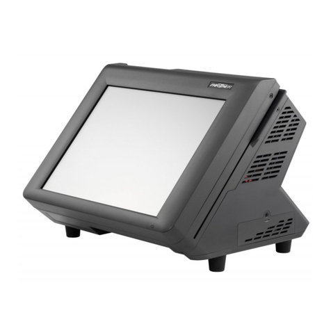
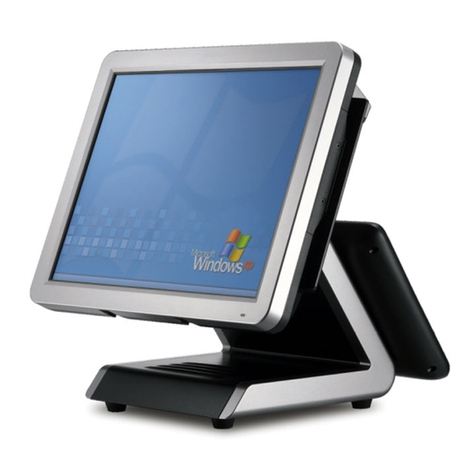
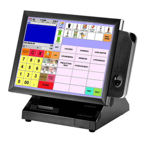
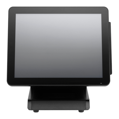
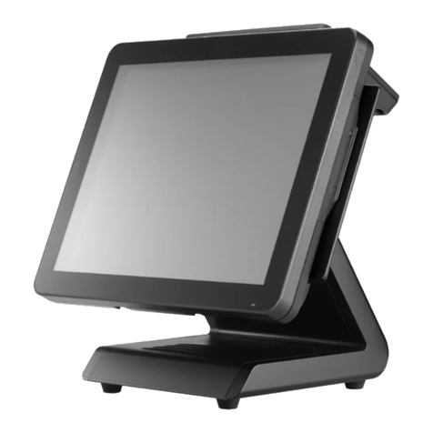
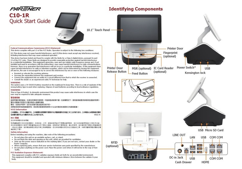
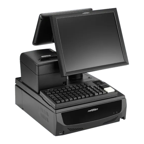
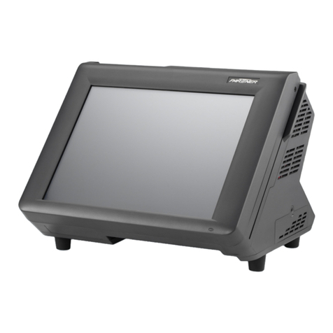
Partner PT-9000 User manual

1
P
PT
T-
-9
90
00
00
0
P
PO
OS
S
T
Te
er
rm
mi
in
na
al
l
User’s Manual
November 27, 2002


i
P
PR
RE
EF
FA
AC
CE
E
C
Co
op
py
yr
ri
ig
gh
ht
t
This publication, including all photographs, illustrations and software, is
protected under international copyright laws, with all rights reserved.
Neither this manual, nor any of the material contained herein, may be
reproduced without written consent of the author.
Copyright 2002
Version 1.0
D
Di
is
sc
cl
la
ai
im
me
er
r
The information in this document is subject to change without notice. The
manufacturer makes no representations or warranties with respect to the
contents hereof and specifically disclaims any implied warranties of
merchantability or fitness for any particular purpose. The manufacturer
reserves the right to revise this publication and to make changes from time
to time in the content hereof without obligation of the manufacturer to notify
any person of such revision or changes.
T
Tr
ra
ad
de
em
ma
ar
rk
k
R
Re
ec
co
og
gn
ni
it
ti
io
on
n
Microsoft, MS-DOS and Windows are registered trademarks of Microsoft
Corp.
Other product names used in this manual are the properties of their
respective owners and are acknowledged.

F
Fe
ed
de
er
ra
al
l
C
Co
om
mm
mu
un
ni
ic
ca
at
ti
io
on
ns
s
C
Co
om
mm
mi
is
ss
si
io
on
n
(
(F
FC
CC
C)
)
This equipment has been tested and found to comply with the limits for a
Class A digital device, pursuant to Part 15 of the FCC Rules. These limits
are designed to provide reasonable protection against harmful interference
in a residential installation. This equipment generates, uses, and can
radiate radio frequency energy and, if not installed and used in accordance
with the instructions, may cause harmful interference to radio
communications. However, there is no guarantee that interference will not
occur in a particular installation. If this equipment does cause harmful
interference to radio or television reception, which can be determined by
turning the equipment off and on, the user is encouraged to try to correct
the interference by one or more of the following measures:
♦Reorient or relocate the receiving antenna.
♦Increase the separation between the equipment and the
receiver.
♦Connect the equipment onto an outlet on a circuit different
from that to which the receiver is connected.
♦Consult the dealer or an experienced radio/TV technician for
help.
Shielded interconnect cables and a shielded AC power cable must be
employed with this equipment to ensure compliance with the pertinent RF
emission limits governing this device. Changes or modifications not
expressly approved by the system's manufacturer could void the user's
authority to operate the equipment.
D
De
ec
cl
la
ar
ra
at
ti
io
on
n
o
of
f
C
Co
on
nf
fo
or
rm
mi
it
ty
y
This device complies with part 15 of the FCC rules. Operation is subject to
the following conditions:
♦This device may not cause harmful interference, and
♦This device must accept any interference received, including
interference that may cause undesired operation.

A
Ab
bo
ou
ut
t
t
th
hi
is
s
M
Ma
an
nu
ua
al
l
The manual consists of the following sections:
♦Chapter 1: Introducing the PT-9000:provides general
information on the POS Terminal, a packing list and
illustrations of the POS Terminal components.
♦Chapter 2: Setting Up the System:provides information on
attaching peripheral and optional devices, as well as starting
the system.
♦Chapter 3:Upgrading the PT-9000: provides instructions for
installing an FDD, CD-ROM drive, or customer pole display,
and installing or upgrading the HDD, memory, and CPU.
Instructions for installing an add-on card are also included.
♦Chapter 4: Installing Driversand Software:provides
detailed information on installing LAN, VGA, and audio drivers.
♦Chapter 5: provides instructions on using the BIOS.
♦Appendix B: Troubleshooting:provides troubleshooting
procedures for the POS Terminal.
♦錯誤! 找不到參照來源。:provides detailed technical
specifications of the POS Terminal.
♦錯誤! 找不到參照來源。:provides jumper settings for the
mainboard and I/O PCB.

S
SA
AF
FE
ET
TY
Y
I
IN
NF
FO
OR
RM
MA
AT
TI
IO
ON
N
Before installing and using the PT-9000 POS Terminal, take note of the
following precautions:
♦Read all instructions carefully.
♦Do not place the unit on an unstable surface, cart, or stand.
♦Do not block the slots and openings on the unit, which are
provided for ventilation.
♦Only use the power source indicated on the marking label. If
you are not sure, contact your dealer or the Power Company.
♦The unit uses a three-wire ground cable, which is equipped
with a third pin to ground the unit and prevent electric shock.
Do not defeat the purpose of this pin. If your outlet does not
support this kind of plug, contact your electrician to replace
your obsolete outlet.
♦Do not place anything on the power cord. Place the power cord
where it will not be in the way of foot traffic.
♦Follow all warnings and cautions in this manual and on the unit
case.
♦Do not push objects in the ventilation slots as they may touch
high voltage components and result in shock and damage to
the components.
♦When replacing parts, ensure that your service technician uses
parts specified by the manufacturer.
♦When service or repairs have been done, ensure that the
service technician performs routine safety checks to verify that
the system is operating correctly.
♦Avoid using the system near water, in direct sunlight, or near a
heating device.
♦Cover the unit when not in use.
♦CB/UL/CUL/CE/FCC/BSMI Approval/VCCI

T
TA
AB
BL
LE
E
O
OF
F
C
CO
ON
NT
TE
EN
NT
TS
S
PREFACE I
Copyright..........................................................................................i
Disclaimer.........................................................................................i
Trademark Recognition....................................................................i
Federal Communications Commission (FCC)..................................ii
Declaration of Conformity...............................................................ii
About this Manual ..........................................................................iii
SAFETY INFORMATION IV
CHAPTER 1:INTRODUCING THE PT-9000 1
A Tour of the PT-9000.....................................................................1
Configuration Options..............................................................................................2
Package Contents......................................................................................................3
Options.........................................................................................................................3
Front View..................................................................................................................4
Rotating the LCD Panel...................................................................5
CHAPTER 2:SETTING UP THE SYSTEM 7
Attaching Peripheral Devices...........................................................7
Connecting I/O Devices....................................................................7
Connecting a PS/2 Keyboard and Mouse.............................................................8
Connecting a Printer.................................................................................................9
Connecting Serial Devices.......................................................................................9
Connecting USB Devices.......................................................................................10
Connecting Audio Speakers..................................................................................10
Connecting to a LAN..............................................................................................11
Connecting the Power Supply...............................................................................11
Turning the System On..........................................................................................12
CHAPTER 3:UPGRADING THE PT-9000 13
Precautions ....................................................................................13
Before You Begin...........................................................................14
Removing the Chassis Covers.........................................................14
Installing a PCI Card.....................................................................18
Installing the RS-110 PCI Card......................................................20

Installing a CD-ROM.....................................................................24
Attaching the Rear Customer Display............................................27
Replacing the Hard Disk Drive ......................................................30
Replacing Memory.........................................................................32
Replacing the CPU.........................................................................35
CHAPTER 4:INSTALLING DRIVERS AND SOFTWARE 41
PT-9000 Driver Installation...........................................................41
Autoinstallation........................................................................................................41
Installing PT-9000 Terminal Drivers..................................................................43
Manual Installation........................................................................54
CHAPTER 5:USING BIOS 63
About the Setup Utility..................................................................63
The Standard Configuration.................................................................................64
Entering the Setup Utility......................................................................................64
Standard CMOS Features .....................................................................................66
Advanced BIOS Features ......................................................................................70
Advanced Chipset Features...................................................................................73
Integrated Peripherals............................................................................................77
Power Management Setup Option.......................................................................82
PnP/PCI Configurations........................................................................................86
PC Health Status .....................................................................................................87
Frequency Control Option.....................................................................................88
Other BIOS Options ......................................................................90
Load Fail-Safe Defaults Option...........................................................................90
Load Optimized Defaults Option..........................................................................91
Set Supervisor and User Passwords Options.....................................................91
Save & Exit Setup Option......................................................................................92
Exit Without Saving................................................................................................92
APPENDIX A:SPECIFICATIONS 93
PT-9000 LCD POS Terminal Specifications ...................................93
APPENDIX B:TROUBLESHOOTING 95
Locating a Problem........................................................................95
Checking Cables and Connections .................................................96
The Power-On Self Test.................................................................96
General Hardware Problems .........................................................97
Contacting Your Dealer.................................................................98
APPENDIX C:JUMPER SETTINGS 99
Mainboard Components ................................................................99
Mainboard Components......................................................................................100
PT-9000 POS PCB Jumper Settings.............................................101
Location of I/O Port PCB Board....................................錯誤! 尚未定義書籤。
PCB Board Settings .....................................................................102
I/O Port PCB ......................................................................錯誤! 尚未定義書籤。

T
TA
AB
BL
LE
E
O
OF
F
F
FI
IG
GU
UR
RE
ES
S
FIGURE 1–SAMPLE CONFIGURATION.................................................................................2
FIGURE 2–PT-9000POS TERMINAL FRONT VIEW..........................................................4
FIGURE 3–VIEW OF I/OPORT ARRAY (BENEATH THE CHASSIS COVER).........................4
FIGURE 4–ROTATING THE LCD PANEL.............................................................................5
FIGURE 5–CONNECTINGPERIPHERAL DEVICES...............................................................7
FIGURE 6–CONNECTINGA PS/2MOUSE ...........................................................................8
FIGURE 7–CONNECTINGA PS/2KEYBOARD.........................................................................8
FIGURE 8–CONNECTINGAPRINTER..................................................................................9
FIGURE 9–CONNECTING A SERIAL DEVICE.......................................................................9
FIGURE 10 –CONNECTING USBDEVICES.......................................................................10
FIGURE 11 –CONNECTING AUDIO SPEAKERS..................................................................10
FIGURE 12 –CONNECTING TO THE LANSTARTINGTHE SYSTEM................................11
FIGURE 13 –CONNECTINGTHEPOWER SUPPLY..............................................................11
FIGURE 14 –TURNING THE SYSTEM ON...........................................................................12
FIGURE 15 –PT-9000 RS-110 PCICARD........................................................................20
FIGURE 16 –PT-9000 MEMORY SLOTS.............................................................................32
FIGURE 17 –PT-9000 CPUAND HEATSINK.....................................................................35
FIGURE 18 –PT-9000 SOFTWAREAUTOINSTALLATION SCREEN....................................41
FIGURE 19 –PT-9000 POSTERMINAL BIOSMAIN SCREEN.........................................64
FIGURE 20 –MAINBOARD COMPONENTS.......................................................................100
FIGURE 21 –I/O PORT PCB..............................................................................................101
FIGURE 22 –I/O PORT PCB JUMPERS.............................................................................102
FIGURE 23 –RS110PCI CARD JUMPERS......................................................................104

1
C
Ch
ha
ap
pt
te
er
r
1
1:
:
I
In
nt
tr
ro
od
du
uc
ci
in
ng
g
t
th
he
e
P
PT
T-
-9
90
00
00
0
A
A
T
To
ou
ur
r
o
of
f
t
th
he
e
P
PT
T-
-9
90
00
00
0
The PT-9000 provides you with a fast and accurate point-of-sales (POS)
solution for use in supermarkets, information kiosks, restaurants, and other
hospitality service areas. The PT-9000 POS Terminal’s mainboard supports
Intel Celeron processors up to 1 GHz, Pentium III processors up to 1.13 GHz,
and VIA C3 700A/900A model processors from 700 to 933 MHz. The
mainboard supports 66/100/133 frontside bus speeds and accommodates
SDRAM memory up to 512 MB.
The PT-9000 mainboard incorporates the innovative Intel 815E chipset,
which delivers superior performance and scalability. The enhanced I/O
Controller Hub (ICH2) in the Intel 815E chipset makes a direct
connection from the graphics and memory for fast access to peripherals
and higher system-level performance. Dual USB controllers provide 12
Mbps data transfer speed. ATA/100 support has been added to enable
fastest file/data transfers. In addition, an Integrated LAN interface has
been engineered into the ICH2. The Intel 815E chipset provides twice the
bandwidth of the PCI bus, as well as dedicated data paths to avoid PCI
bottlenecks.
The PT-9000 comes with the following I/O interfaces:
•1 parallel port
•4 standard serial ports (COM 1/2/C/D), 2 Phone jack to serial port
withsupport 5 and 12 volts DC output.
•1 Ethernet, 10/100 BASE-T port
•1 PS/2 keyboard port
•1 PS/2 mouse port
•1 VGA port
•2 USB ports
•1 audio jack
•1 microphone jack

2
C
Co
on
nf
fi
ig
gu
ur
ra
at
ti
io
on
n
O
Op
pt
ti
io
on
ns
s
The PT-9000 POS Terminal can support many optional devices:
Figure 1–Sample configuration
Printer
Customer
pole display
Slim
-
type
CD-ROM
PT-9000 POS Terminal

3
P
Pa
ac
ck
ka
ag
ge
e
C
Co
on
nt
te
en
nt
ts
s
The PT-9000 POS Terminal comes securely packaged in a sturdy
cardboard shipping carton. Upon receiving the PT-9000 POS Terminal,
open the carton and carefully remove the contents. If anything is missing
or damaged, please contact your dealer immediately. The shipping carton
should contain the following items:
•1 PT-9000 POS Terminal
•1 AC power cord
•2 Serial cables
•Screws
•Support driver and utility CD-ROM or diskettes
•This user’s manual
•2 Keys
O
Op
pt
ti
io
on
ns
s
•Customer display (CD7220/3160/3220)
•Disk storage –3.5-inch 20 GB HDD
•1/2/3 track Magnetic Strip Reader (MSR)
•RS-110 card
•POS printer

4
F
Fr
ro
on
nt
t
V
Vi
ie
ew
w
Figure 2–PT-9000 POS Terminal front view
Figure 3–View of I/O port array (beneath the chassis cover)

5
R
Ro
ot
ta
at
ti
in
ng
g
t
th
he
e
L
LC
CD
D
P
Pa
an
ne
el
l
The LCD panel can be rotated back to provide convenient access to the
hard disk drive (HDD). This rotation provides flexible viewing angles for
all types of environments:
50
Figure 4–Rotating the LCD panel

6
—Notes—

7
C
Ch
ha
ap
pt
te
er
r
2
2:
:
S
Se
et
tt
ti
in
ng
g
U
Up
p
t
th
he
e
S
Sy
ys
st
te
em
m
A
At
tt
ta
ac
ch
hi
in
ng
g
P
Pe
er
ri
ip
ph
he
er
ra
al
l
D
De
ev
vi
ic
ce
es
s
The PT-9000 POS Terminal supports many peripheral devices to expand
the functionality of the terminal. All of these connections are made on the
I/O port array located underneath the rear chassis cover. (To remove the
rear chassis cover, refer to Removing the Chassis Covers on page 14.)
C
Co
on
nn
ne
ec
ct
ti
in
ng
g
I
I/
/O
O
D
De
ev
vi
ic
ce
es
s
COMD4COMCPRINTER
VGACOM1
COM2
USB
NET
SPKRCARD
PS/2
PS/2Mouse
P
O
S
P
r
i
n
t
e
r
Network
(LAN)
USB
Compliant
Device
Printer
E
x
t
e
r
n
a
l
S
p
e
a
k
e
r
s
M
i
c
r
o
p
h
o
n
e
S
e
r
i
a
l
M
o
u
s
e
o
r
G
r
a
p
h
i
c
s
T
a
b
l
e
t
Serial
Mouse orGraphics
Tablet
Touch
S
c
r
e
e
n
C
u
s
t
o
m
e
r
D
i
s
p
l
a
y
Card Swipe
VGA Monitor
To Monitor
K
e
y
b
o
a
r
d
From Monitor
M
I
C
Figure 5–Connecting peripheral devices

8
C
Co
on
nn
ne
ec
ct
ti
in
ng
g
a
a
P
PS
S/
/2
2
K
Ke
ey
yb
bo
oa
ar
rd
d
a
an
nd
d
M
Mo
ou
us
se
e
Connect a mouse to the PS/2
port located beneath the chassis
cover.
Note! The purple PS/2 port is
for the card swipe and the
green PS/2 port is for the
mouse.
Connect a keyboard to the PS/2
female plug originating from the
back of the monitor.
If your keyboard has an AT
type connector, you must use
an adapter. Contact your
dealer for details.
You can also connect a CCD
(barcode scanner) to the PS/2
keyboard port.
Figure 6–Connecting a PS/2 mouse
Touch
Screen
Figure7–Connecting a PS/2 keyboard

9
C
Co
on
nn
ne
ec
ct
ti
in
ng
g
a
a
P
Pr
ri
in
nt
te
er
r
Connect a printer to the standard 25-pin D-type parallel connector.
Connect an optional POS printer to the COMC port:
Printer
Figure 8–Connecting a printer
C
Co
on
nn
ne
ec
ct
ti
in
ng
g
S
Se
er
ri
ia
al
l
D
De
ev
vi
ic
ce
es
s
Connect serial devices, such as a CCD barcode scanner or Smart Card
reader, to the 9-pin D-type serial ports:
Caution! These serial ports are voltage selectable and can cause
damage to external devices if not set up correctly. Refer
to Appendix C for serial port voltage settings via jumper.
Serial
Mouse
or
Graphics
Tablet
COMC COMD
Figure 9–Connecting a serial device

10
C
Co
on
nn
ne
ec
ct
ti
in
ng
g
U
US
SB
B
D
De
ev
vi
ic
ce
es
s
Connect USB devices to either of the two USB ports:
USB
Compliant
Device
Figure 10 –Connecting USB devices
C
Co
on
nn
ne
ec
ct
ti
in
ng
g
A
Au
ud
di
io
o
S
Sp
pe
ea
ak
ke
er
rs
s
External
Speakers
Figure 11 –Connecting audio speakers
Note! You must install the audio drivers before you can hear audio output through the
speakers. Refer to Installing Audioon page 55.
Table of contents
Other Partner Touch Terminal manuals

Partner
Partner SP-1000 User manual

Partner
Partner PT-6212 User manual

Partner
Partner PT-1630 User manual

Partner
Partner PAT-215 User manual

Partner
Partner CD-70 User manual

Partner
Partner SP-820 User manual

Partner
Partner PT-6200 User manual

Partner
Partner PT-6910 Series User manual

Partner
Partner SP-1060 User manual

Partner
Partner SP-820 User manual

Partner
Partner PT-1300 User manual

Partner
Partner OT-310 User manual

Partner
Partner SP-2600 User manual

Partner
Partner KB-18LD2 User manual

Partner
Partner SP-550 User manual

Partner
Partner E5-1-K User manual

Partner
Partner SP-1060 IoT Ready User manual

Partner
Partner SP-800 User manual

Partner
Partner SP-600-A User manual

Partner
Partner PT-6900 User manual