Partner PT-6200 User manual

PT-6200
User Manual


i
Copyright
This publication, including all photographs, illustrations and software, is protected under international
copyright laws, with all rights reserved. Neither this manual, nor any of the material contained herein, may be
reproduced without written consent of the author.
Disclaimer
The information in this document is subject to change without notice. The manufacturer makes no representa-
tions or warranties with respect to the contents hereof and specically disclaims any implied warranties of
merchantability or tness for any particular purpose. The manufacturer reserves the right to revise this publi-
cation and to make changes from time to time in the content hereof without obligation of the manufacturer to
notify any person of such revision or changes.
Trademark recognition
All product names used in this manual are the properties of their respective owners and are acknowledged.
Federal Communications Commission (FCC)
This equipment has been tested and found to comply with the limits for a Class A digital device, pursuant to
Part 15 of the FCC Rules. These limits are designed to provide reasonable protection against harmful interfer-
ence in a residential installation. This equipment generates, uses, and can radiate radio frequency energy
and, if not installed and used in accordance with the instructions, may cause harmful interference to radio
communications. However, there is no guarantee that interference will not occur in a particular installation. If
this equipment does cause harmful interference to radio or television reception, which can be determined by
turning the equipment off and on, the user is encouraged to try to correct the interference by one or more of
the following measures:
Reorient or relocate the receiving antenna.
Increase the separation between the equipment and the receiver.
Connect the equipment onto an outlet on a circuit different from that to which the receiver is connected.
Consult the dealer or an experienced radio/TV technician for help.
Shielded interconnect cables and a shielded AC power cable must be employed with this equipment to ensure
compliance with the pertinent RF emission limits governing this device. Changes or modications not ex-
pressly approved by the system’s manufacturer could void the user’s authority to operate the equipment.
Declaration of conformity
This device complies with part 15 of the FCC rules. Operation is subject to the following conditions:
This device may not cause harmful interference, and
This device must accept any interference received, including interference that may cause undesired operation.

ii
About this manual
This manual is intended for system administrators who are familiar with setting up a new system and install-
ing an operating system.
The manual consists of the following sections:
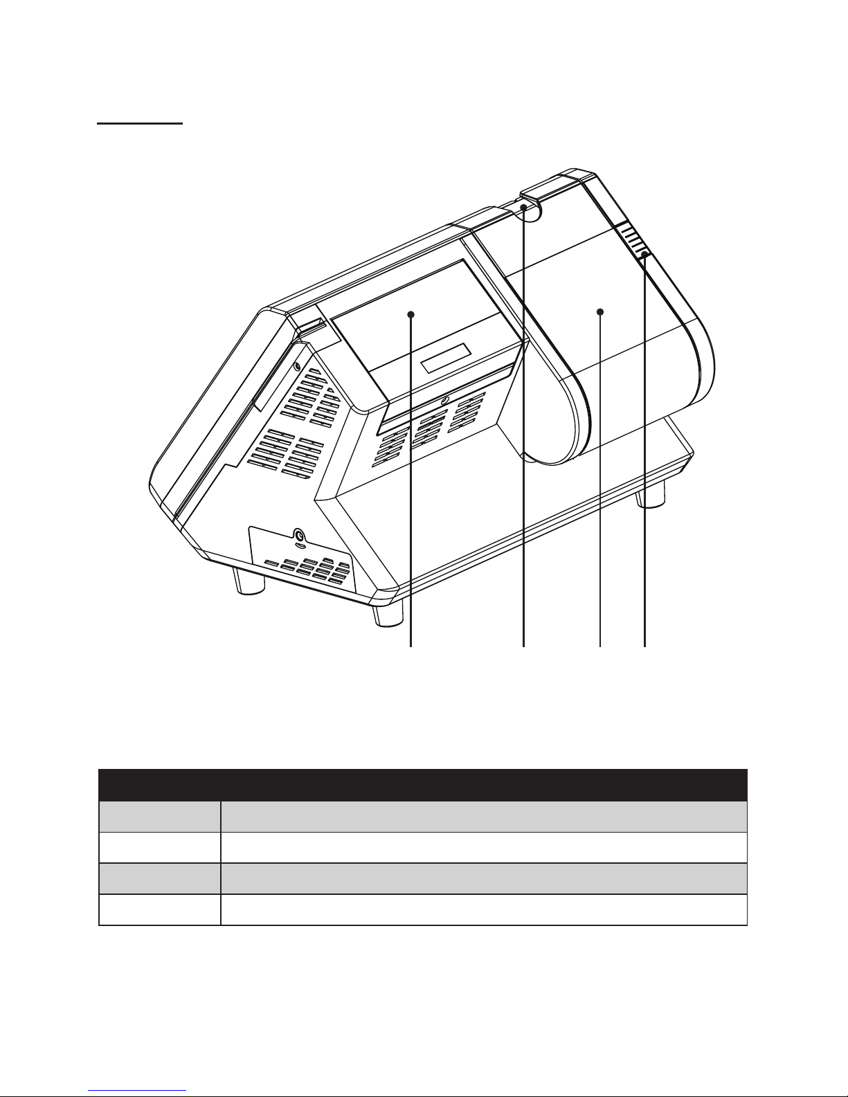
Chapter 1 Getting Started: This section covers unpacking and checking the
package contents, and identifying components.
Information on connecting peripheral devices, and
powering on is also provided.
Chapter 2 BIOS Setup Utility: The BIOS chapter provides information on navigating
and changing settings in the BIOS Setup Utility.
Chapter 3 Upgrading Components: This section provides information on upgrading
components.
Appendix: The appendix covers troubleshooting, information
on having the PT-6200 serviced, and technical
specications.
Safety information
Before installing and using the PT-6200 POS, take note of the following precautions:
Read all instructions carefully.•
Do not place the unit on an unstable surface, cart, or stand.•
Do not block the slots and opening on the unit, which are provided for ventilation.•
Do not push objects in the ventilation slots as they may touch high voltage components and result in•
shock and damage to the components.
Only use the power source indicated on the marking label. If you are not sure, contact your dealer or the•
Power Company.
The unit uses a three-wire ground cable, which is equipped with a third pin to ground the unit and•
prevent electric shock. Do not defeat the purpose of this pin. If your outlet does not support this kind of
plug, contact your electrician to replace your obsolete outlet.
Do not place anything on the power cord. Place the power cord where it will not be in the way of foot•
trafc.
Follow all warnings and cautions in this manual and on the unit case.•
When replacing parts, ensure that your service technician uses parts specied by the manufacturer. •
Avoid using the system near water, in direct sunlight, or near a heating device.•
WARNING
The system uses a 3V CR2032 battery mounted on the mainboard to
keep time. There is a risk of explosion if the wrong battery type is used
when replacing. Dispose of used batteries according to local ordinance
regulations.
CAUTION
The USB ports can be damaged if care is not taken when connecting
devices. Ensure USB devices are correctly inserted.
Plugging a phone line into the LAN port (RJ-45 connector) can damage
the connector. Take care only plug an RJ-45 connector into the LAN port.
Revision history
Version 1.0, April 2008

iii
TABLE OF CONTENTS
CHAPTER 1 GETTING STARTED................................................ 1
Unpacking the machine .................................................................................1
Checking the package contents ....................................................................2
Identifying components .................................................................................3
Connecting peripheral devices.......................................................................6
Connecting a cash drawer .............................................................................7
Powering the machine on and off...................................................................8
Installing the thermal paper roll......................................................................9
Printer Setting under Windows XP Professional..........................................10
CHAPTER 2 BIOS SETUP.......................................................... 13
About the Setup Utility .................................................................................13
Entering the Setup Utility ........................................................................14
BIOS navigation keys ..............................................................................14
Using BIOS .............................................................................................15
Standard CMOS features.............................................................................16
Advanced BIOS Features ............................................................................18
Advanced Chipset Features.........................................................................20
Integrated Peripherals..................................................................................22
►OnChip IDE Device .............................................................................23
►OnChip PCI Device .............................................................................24
►SuperIO Device...................................................................................25
Power Management Setup...........................................................................26
PnP/PCI Congurations ...............................................................................28
► IRQ Resources....................................................................................29
PC Health Status..........................................................................................30
Frequency/Voltage Control...........................................................................31
Other BIOS Options .....................................................................................32
CHAPTER 3 UPGRADING COMPONENTS............................... 35
Safety and precautions ...............................................................................35
Before you begin .........................................................................................36
Upgrading the hard drive..............................................................................37
APPENDIX .................................................................................. 39
Troubleshooting ...........................................................................................39

iv
Tips for Troubleshooting...............................................................................39
The Power-On Self Test ...............................................................................39
Beep Errors at POST ...................................................................................39
Beep Message Errors at POST ...................................................................40
General Problems .......................................................................................41
Having the PT-6200 Serviced .....................................................................42
Specications...............................................................................................43

1
CHAPTER 1
GETTING STARTED
This chapter describes the procedures from unpacking the PT-6200 POS, to powering it on. The following
topics are described.
Unpacking the machine on page• 1
Checking the package contents on page• 2
Identifying components on page• 3
Connecting peripheral devices on page• 6
Connecting a cash drawer on page• 7
Powering the machine on and off on page• 8
Installing the thermal paper roll on page• 9
Printer Setting under Windows XP Professional on page 1• 0
Unpacking the machine
The machine and cable accessories are packed in a cardboard carton with foam padding for protection during
shipping.
Figure 1.1 Unpacking the
machine
Carefully unpack the machine and keep the packing materials. If you need to ship it in the future, repack it as
shown in Figure 1.1.

2 CHAPTER 1 GETTING STARTED
Checking the package contents
After you unpack the device check that the following items are included.
If any item is missing or appears damaged, contact your dealer immediately.
PT-6200
Adapter
Power Cable
3” thermal paper roll
PT-6200
User Manual
Driver CD with drivers and
the user manual PDF le.
(This) User Manual

3
Identifying components
This section describes the parts and connectors on the machine.
Front-right view
1 52
Figure 1.2 Front-right view
Component Description
1 Power Button
2 10.4-inch TFT LCD; 5-wire Resistive touch
3 IO Panel
4 LED Power Indicator
5 Tripple-track MSR
3 4

4 CHAPTER 1 GETTING STARTED
Rear view
1
Figure 1.3 Rear view
Component Description
1 2x20 VFD customer display
2 Printer paper exit
3 80mm thermal receipt printer
4 Printer button
32 4

5
I/O connectors
Figure 1.4 PT-6200 I/O connectors
4
1 2 3
5 6 7 8 9
Connector Description
1 COM4 port
2 COM2 port
3 LAN port (RJ-45)
4 12V power connector
5 PS/2 keyboard port
6 RJ-11 cash drawer port
7 COM3 port
8 COM1 port
9 USB ports

6 CHAPTER 1 GETTING STARTED
Figure 1.7 Connecting peripheral devices
Connecting peripheral devices
Peripheral devices such as a printer or scanner can be connected to the machine. Refer to the user manual of
the device you are connecting for instructions on installing drivers where needed.
Keyboard
Cashdrawer
USB Compliant
devices
Adapter ADSL modem or router
MR HS AA CD OH SD RD TR
CAUTION
Do not plug a phone line into the RJ-45 (ADSL or router) connector.
Doing so can damage the connector.

7
Connecting a cash drawer
Refer to the following to connect a cash drawer.
IMPORTANT
The cash drawer RJ-11 connector is DC+24V. Ensure the cash drawer
to be connected matches this power specication.
Locate the I/O panel that is at the1.
bottom of the machine.
Connect the RJ-11 cable from the2.
cash drawer to the RJ-11 connec-
tor on the I/O Panel.
Cashdrawer

8 CHAPTER 1 GETTING STARTED
Powering the machine on and off
Refer to the following to power on and off the machine.
Locate the I/O panel that is at the1.
bottom of the machine.
Connect the adapter to the2.
power cable, and then insert the
power plug into an electrical outlet
(AC100 - 240 V).
Press the power button, it’s at the3.
bottom left of the machine. The
power LED turns on.
To turn off the machine, shut down4.
the operating system. The main
power turns off automatically.
NOTE
You may need to force power off the machine, for example if the
operating system you are using does not support power down by the OS
or if the system crashes or hangs. To force power off , long press the
power button for ve seconds.

9
Installing the thermal paper roll
Refer to the following to install the thermal paper roll.
Press the release and open the printer cover.1.
Insert the thermal paper roll as2.
shown on the picture.
Pull a portion of the paper over the3.
printer output part.
Close the cover and press it down4.
until you feel a click.
NOTE
After installation,
the printer will
automatically feed
a few lines.

10 CHAPTER 1 GETTING STARTED
Printer Setting under Windows XP Professional
Start → Settings → Printers 1.
and Faxes
Right click on “LK-T60” and2.
select “Properties”.
Select “COM5: Serial Port”3.
Click on “Apply”.4.
Select “Congure Port” to 5.
enter “COM5 Properties”.

11
Set the Bits per second to6.
“115200”.
Set the Flow control to “Hard-7.
ware”.
Click on “Apply”.8.
Click on “OK”.9.

12 CHAPTER 1 GETTING STARTED

13
CHAPTER 2
BIOS SETUP
The primary function of the BIOS (Basic Input and Output System) is to identify and initiate component
hardware. The BIOS parameters are stored in non-volatile BIOS memory (CMOS). CMOS contents don’t get
erased when the computer is turned off. The following topics are described in this chapter.
About the Setup Utility on page 1• 3
Standard CMOS features on page 1• 6
Advanced BIOS Features on page 1• 8
Advanced Chipset Features on page 2• 0
Integrated Peripherals on page 2• 2
Power Management Setup on page 2• 6
PnP/PCI Congurations on page 2• 8
PC Health Status on page 3• 0
Frequency/Voltage Control on page 3• 1
Other BIOS Options on page 3• 2
About the Setup Utility
The BIOS Setup Utility enables you to congure the following items:
Hard drives, diskette drives, and peripherals•
Video display type and display options•
Password protection from unauthorized use•
Power management features•
This Setup Utility should be used for the following:
When changing the system conguration •
When a conguration error is detected and you are prompted to make changes to the Setup Utility •
When trying to resolve IRQ conicts •
When making changes to the Power Management conguration •
When changing the User or Supervisor password•

14 CHAPTER 2 BIOS SETUP
Entering the Setup Utility
When you power on the system, BIOS enters the Power-On Self Test (POST) routines. POST is a series of
built-in diagnostics performed by the BIOS. After the POST routines are completed, the following message
appears:
Press DEL to enter SETUP
Press the delete key <Delete> to access the Award BIOS Setup Utility:
BIOS navigation keys
The BIOS navigation keys are listed below.
Key Function
←↑↓→ Scrolls through the items on a menu
+/–/PU/PD Modies the selected eld’s values
Esc Exits the current menu
F1 Displays a screen that describes all key functions
F5 Loads previously saved values to CMOS
F6 Loads a minimum conguration for troubleshooting
F7 Loads an optimum set of values for peak performance
F10 Saves the current conguration and exits Setup
Shift + F2 Changes the color of the BIOS menu
Phoenix - AwardBIOS CMOS Setup Utility
Standard CMOS Feature►
Advanced BIOS Features►
Advanced Chipset features►
Integrated Peripherals►
Power Management Setup►
PnP/PCI Congurations►
PC Health Status►
Frequency/Voltage Control►
Load Fail-Safe Defaults
Load Optimized Defaults
Set Supervisor Password
Set User Password
Save & Exit Setup
Exit Without Saving
Esc : Quit
F10 : Save & Exit Setup
↑ ↓ → ← : Select Item
Time, Date, Hard Disk Type...
Main BIOS menuFigure 2.1
Table of contents
Other Partner Touch Terminal manuals

Partner
Partner SP-850 User manual

Partner
Partner SP-1000-C User manual

Partner
Partner SP-650-S User manual

Partner
Partner PT-1300 User manual

Partner
Partner PT-5900 User manual

Partner
Partner SP-550 User manual

Partner
Partner C14-1E User manual

Partner
Partner CD-70 User manual

Partner
Partner PT-5700 User manual

Partner
Partner C10-1R User manual

Partner
Partner SP-1000-C User manual

Partner
Partner PT-5910 User manual

Partner
Partner SP-820 User manual

Partner
Partner SP-1000-BZ User manual

Partner
Partner SP-1030 User manual

Partner
Partner PT-1630 User manual

Partner
Partner SP-600-A User manual

Partner
Partner PT-5900 User manual

Partner
Partner E5-1-K User manual

Partner
Partner PT-6910 Series Manual