Model No.EM-8678A Equipment Setup
3
Using the Charge/Discharge Circuit with a sensor such as the Voltage/Current Sensor requires a PASCO com-
puter interface and data acquisition software (such as the UI-5000 850 Universal Interface and UI-5400 PASCO
Capstone).
Equipment Setup
You will need two “AA” or “AAA” batteries (not included), three #14 GE Mini Light Bulbs (included), and a set
of banana plug patch cords (not included).
For real-time data recording*, you will need a PASPORT Voltage/Current Sensor and a PASCO computer inter-
face with data acquisition software (such as the UI-5000 850 Universal Interface and UI-5400 PASCO Cap-
stone). NOTE: If you use the PASCO Capstone software, you can also use the ScienceWorkshop CI-6503 Voltage
Sensor and the ScienceWorkshop CI-6556 Current Sensor with either the UI-5100 850 Universal Interface or the
CI-7650 750 ScienceWorkshop Interface.
*See Appendix B for a typical experiment setup option.
Inserting/Replacing the Batteries
When inserting the batteries, follow the orientation for the posi-
tive and negative ends of the batteries shown on the battery
holders. A set of AA alkaline batteries can be ordered from
PASCO (PI-6601 pack of 4).
For Ohm’s law studies, alkaline batteries or re-rechargeable
batteries can be used.
Inserting/Replacing the Light Bulbs
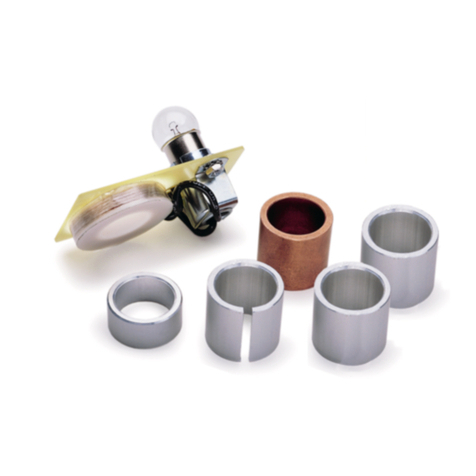
A set of three 3-volt light bulbs comes with the Charge/Discharge Circuit. To remove a burnt out bulb, turn the
bulb counterclockwise and lift out. To replace a bulb, insert the bulb into one of the plastic slots (slot A, B, or C)
and turn the bulb clockwise until it fits tightly into the slot. For the bulb to light, the bulb tip must maintain con-
tact with the metal piece in the slot.
CAUTION: To avoid overloading the circuit, do not use bulbs greater than a 3 volt capacity.
Using the Double-Throw Switch
The double-throw switch is used to control the path of the electrical current through the components on the
Charge/Discharge Circuit.
For the Ohm’s Law circuit, for example, when the switch lever is in the “Charge Position,” energy from the bat-
teries can be routed to the capacitor. Moving the lever to the “Discharge Position” allows the capacitor to dis-
charge energy through a resistor or light bulb or other component that is connected. For example, if a light bulb is
connected, as the energy dissipates as heat and light, the bulb slowly becomes dim.
Connecting External Devices to the Charge/Discharge Circuit
The Charge/Discharge Circuit was designed to be used with PASCO sensors, meters, and external power sup-
plies. Connecting an external device requires a set of banana plug patch cords (i.e. at least one positive and one
negative banana patch cord, such as the SE-7123 Banana Plug Patch Cords (set of 8)).
The board has three positive, three negative, and nine neutral (unlabeled) shrouded banana jack connectors. The
connectors with the (+) label are for inserting positive leads and the connectors with the (-) label are for inserting
negative leads. The neutral connectors are for connecting either positive or negative leads, depending on your
setup.
Inserting batteries into the battery holders
