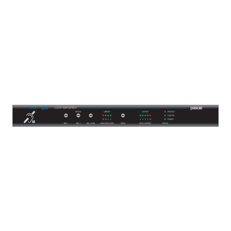
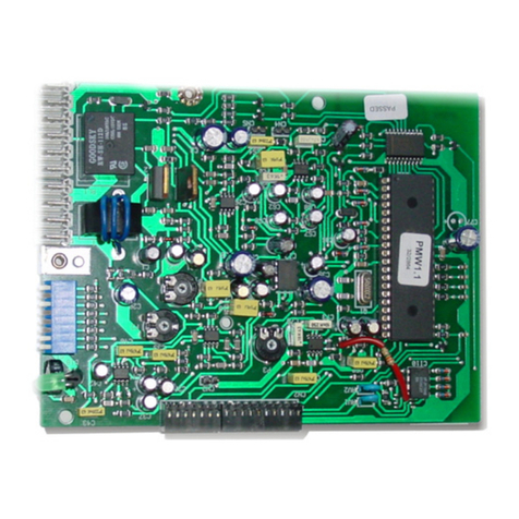
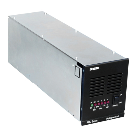
Paso PMW60-B User manual

- PMS2000 System - 1
PMW60-B
PMW120-B
PMW240-B
SISTEMA MODULARE PROFESSIONALE PMS2000
PMS2000 PROFESSIONAL MODULAR SYSTEM
Istruzioni per l’uso
Instructions for use
Manuel d’utilisation
Gebrauchsanleitung
Gebruiksinstructies
Instrucciones de empleo
60/120/240 W
Amplificatori
Amplifiers
Amplificateurs
Verstärker
Amplificadores
Versterkers
11-672_senza concatenamento.indd1 111-672_senza concatenamento.indd1 1 22/03/2010 14.57.0122/03/2010 14.57.01

PMW60-B, PMW120-B, PMW240-B Ref. 11/500-B
2-PMS2000 System -
INTRODUZIONE
Nel ringraziarVi per aver scelto un prodotto PASO, vogliamo
ricordarVi che la nostra azienda opera con sistema di qualità
certificato. Tutti i nostri prodotti vengono pertanto controllati in
ogni fase della produzione per garantirVi la piena soddisfazione
del Vostro acquisto. Per ogni evenienza la garanzia coprirà,
nell’anno di validità, eventuali difetti di fabbricazione.
Vi raccomandiamo di leggere attentamente le seguenti istruzioni
d’uso per sfruttare appieno le prestazioni offerte da questo prodotto
e per evitare eventuali problemi.
INTRODUCTION
While thanking you for having chosen a PASO product, we
would like to remind you that our company works according
to a certified Quality System. This means that all our products
are checked during every phase of manufacturing in order to
guarantee that you will be fully satisfied with your purchase.
At all events, the guarantee will cover any manufacturing flaws
for the whole year for which it is valid. We recommend that
you read the following instructions for use carefully in order
to exploit in full the performance of this product and to avoid
any problems.
SOMMARIO
1. Descrizione generale............................................ 3
1.1 Pannelli frontali......................................................... 3
1.2 Pannelli posteriori..................................................... 3
2. Avvertenze generali.............................................. 4
2.1 Installazione............................................................. 4
2.2 Montaggio a rack degli amplificatori.......................... 4
2.3 Alimentazione e messa a terra .................................. 5
2.4 Note di sicurezza ...................................................... 5
3. Connessioni ........................................................... 6
3.1 Criteri generali.......................................................... 6
3.2 Ingresso/uscita di linea............................................. 6
3.3 Uscite di potenza...................................................... 6
3.3.1 Regolazione del volume ............................................ 6
3.3.2 Sistemi a tensione costante ...................................... 6
3.3.3 Calcolo del numero di diffusori
(tramite le potenze).................................................. 7
3.3.4 Calcolo del numero di diffusori
(tramite le impedenze) ............................................. 7
3.4 Filtro selettivo parola................................................ 8
3.5 Moduli accessori interni ............................................ 8
3.5.1 Scheda traslatore di linea ......................................... 9
3.5.2 Scheda di controllo ................................................... 9
4. Uso dell’apparecchio .......................................... 10
4.1 Accensione ............................................................. 10
4.2 Display ................................................................... 10
5. Note di servizio ................................................... 11
5.1 Ventilazione forzata ................................................ 11
5.2 Condizioni di sovraccarico e protezioni.................... 11
5.3 Tarature................................................................. 11
6. Lista degli accessori............................................12
Lista parti di ricambio ...................................................12
Caratteristiche tecniche...............................................13
TABLE OF CONTENTS
1. General description............................................. 3
1.1 Front panels ............................................................. 3
1.2 Rear panels ............................................................. 3
2. General warnings.................................................. 4
2.1 Installation ............................................................... 4
2.2 Mounting the amplifiers in a rack .............................. 4
2.3 Power supply and connection to earth ...................... 5
2.4 Notes on safety ........................................................ 5
3. Connections........................................................... 6
3.1 General criteria......................................................... 6
3.2 Ingresso/uscita di linea............................................. 6
3.3 Power outputs .......................................................... 6
3.3.1 Volume control ......................................................... 6
3.3.2 Constant-voltage systems......................................... 6
3.3.3 Calculating the number of loudspeakers
(on the basis of the power output) ........................... 7
3.3.4 Calculating the number of loudspeakers
(on the basis of the impedance) ............................... 7
3.4 Selective speech filter............................................... 8
3.5 Internal accessory modules ...................................... 8
3.5.1 Line transformer card ............................................... 9
3.5.2 Control card ............................................................. 9
4. Using the equipment .......................................... 10
4.1 Switching on........................................................... 10
4.2 Display ................................................................... 10
5. Service notes....................................................... 11
5.1 Forced ventilation................................................... 11
5.2 Overload conditions and protection devices............. 11
5.3 Calibration.............................................................. 11
6. List of accessories.................................................12
Spare parts list ..............................................................12
Technical specifications ..............................................13
11-672_senza concatenamento.indd2 211-672_senza concatenamento.indd2 2 22/03/2010 14.57.0522/03/2010 14.57.05

- PMS2000 System - 3
Ref. 11/500-B PMW60-B, PMW120-B, PMW240-B
1. DESCRIZIONE GENERALE
1.1 Pannelli frontali
1) Feritoie di aerazione anteriori.
2) Spia di accensione.
3) Display a led.
4) Interruttore di rete.
1.2 Pannelli posteriori
5) Morsettiera collegamento diffusori ed alimentazione
esterna in corrente continua.
6) Feritoie di aerazione posteriori.
7) Spina di rete con fusibile incorporato.
8) Fusibile di protezione dell’alimentazione in c.c.
9) Predisposizioni per connessioni ed impostazioni delle
schede di controllo (PM2092 o PM2092/2-V).
10) Prese per ingresso/uscita di linea.
11) Regolatore volume di uscita.
1. GENERAL DESCRIPTION
1.1 Front panels
1) Front ventilation slits.
2) ON/OFF signalling lamp.
3) LED display.
4) Main power switch.
1.2 Rear panels
5) Terminal strip for connecting the loudspeakers and an
external DC power supply.
6) Rear ventilation slits.
7) Mains plug with built-in fuse.
8) Fuse for protecting the DC power supply.
9) Arrangements for connections and setting of the
control cards (PM2092-V or PM2092/2-V).
10) Sockets for line input/output.
11) Output volume controller.
POWER AMPLIFIER
PMW120-B
TO REDUCE THE RISK OF FIRE,
REPLACE ONLY WITH SAME
TYPE FUSE.
DISCONNECT POWER SUPPLY CORD
BEFORE CHANGING FUSE.
:
SUPPLY VOLTAGE
POWER CONSUMPTION
POWER RATING
230V
250W
120W RMS
8A
24V
MADE IN ITALY
CAUTION:
CAUTION
TO POWER OUTPUT
TO SPEAKER LINE ‘B’
IN +
IN -
1
2
3
4
5
6
7
8
9
10
TO SPEAKER LINE ‘A’
LINE
REMOTE VOL.
INPUT
min. 10 k LIN.
RELAY CONTACT
RELAY CONTACT
I max 1A
V max 30V
C
O
N
T
R
O
L
I
O
PM2092/2-V
TO POWER OUTPUT
NORMAL CLOSED
IN +
IN -
1
2
3
4
5
6
7
8
9
10
TO SPEAKER LINE
LINE
REMOTE VOL.
INPUT
min. 10 k LIN.
COMMON
NORMAL OPEN
I max 3A
V max 100V
C
O
N
T
R
O
L
I
O
PM2092-V
RELAY
11-672_senza concatenamento.indd3 311-672_senza concatenamento.indd3 3 22/03/2010 14.57.0522/03/2010 14.57.05

PMW60-B, PMW120-B, PMW240-B Ref. 11/500-B
4-PMS2000 System -
2. AVVERTENZE GENERALI
2.1 Installazione
Tutti gli apparecchi PASO sono costruiti nel rispetto delle più
severe normative internazionali di sicurezza ed in ottemperanza
ai requisiti della Comunità Europea. Per un corretto ed efficace
uso dell’apparecchio è importante prendere conoscenza di tutte
le caratteristiche leggendo attentamente le presenti istruzioni ed
in particolare le note di sicurezza. Durante il funzionamento
dell’apparecchio è necessario assicurare un’adeguata ventilazione.
Evitare di racchiudere l’apparecchio in un mobile privo di aerazione
o di ostruirne le fessure di ventilazione. Evitare inoltre di tenere
l’apparecchio in prossimità di sorgenti di calore (termosifoni,
impianti di riscaldamento, ecc.). Prima dell’accensione assicurarsi
che tutti gli ingressi e le uscite siano correttamente collegati.
2. GENERAL WARNINGS
2.1 Installation
All PASO equipment is built according to the strictest international
safety standards and complies with European Community
requisites. In order to use the equipment correctly and effectively,
it is important to be aware of all its features by reading these
instructions and in particular the notes on safety carefully. While
the equipment is working, it is necessary to ensure adequate
ventilation. Avoid closing the equipment inside a cabinet without
ventilation and take care not to obstruct the ventilation slits.
Also avoid keeping the equipment near a source of heat (radiator,
heating systems and so on).
Before switching on the equipment, make sure that all the inputs
and outputs are correctly connected.
2.2 Montaggio a rack degli amplificatori
Per l’installazione degli amplificatori PMW60-B, PMW120-B e
PMW240-B all’interno di mobili rack a 19” è necessario utilizzare
l’apposito cestello di supporto (vedi lista degli accessori a pag. 12);
ogni cestello può portare fino a quattro amplificatori PMW60-B/
PMW120-B o due amplificatori PMW240-B. Si raccomanda di
seguire attentamente le indicazioni di seguito riportate per una
corretta installazione dei cestelli all’interno dei mobili rack:
2.2 Mounting the amplifiers in a rack
To install the PMW60-B, PMW120-B and PMW240-B amplifiers
in a 19” rack cabinet, it is necessary to use the supporting modules-
cage provided for this purpose (see list of accessories on page 12).
Each modules-cage can contain up to four PMW60-B/PMW120-B
amplifiers or two PMW240-B amplifiers. Make sure you follow the
instructions given below carefully to install the modules-cages
inside the rack cabinets properly:
Fig. 2.2.1
A
- il cestello di supporto
degli amplificatori (vedi
fig. 2.2.1) deve sempre
essere montato sulle
apposite staffe di sostegno
(particolare [A]) fornite in
dotazione.
- tra un cestello ed un altro,
o tra un cestello e gli altri
apparecchi montati nel
rack, deve sempre essere
interposto un pannello di
aerazione di almeno una
unità rack; nel caso in cui
nel rack venga installato un
solo cestello, il pannello di
aerazione superiore può
essere omesso.
- the supporting modules-
cage for the amplifiers
(see figure 2.2.1) must
always be mounted on
the supporting brackets
provided for this purpose
(detail [A]) included in the
supply.
- a ventilation panel
occupying at least one
rack unit must always be
mounted between one
modules-cage and the next,
or between a modules-cage
and any other equipment
mounted in the same rack.
If only one modules-cage
is installed in the rack, the
upper ventilation panel
may be omitted.
Per montare un amplificatore è necessario:
A) inserire l’amplificatore nel cestello facendo attenzione che le
feritoie di ventilazione inferiori dell’amplificatore (presenti solo
nel modello PMW240-B) coincidano con le apposite aperture
praticate nel cestello.
To mount an amplifier in the modules-cage it is necessary to:
A) Insert the amplifier inside the modules-cage making sure that
the lower ventilation slits on the amplifier (present only on
model PMW240-B) coincide with the corresponding openings
in the modules-cage.
B) Secure the amplifier
to the modules-cage
following the mounting
instructions attached to
the latter. To fix the rear
side, use the screw(s)
(detail [A]) as illustrated in
Figure 2.2.2.
B) fissare l’amplificatore
al cestello seguendo le
istruzioni di montaggio
allegate a quest’ultimo;
utilizzare, per il fissaggio
del lato posteriore, la/e
vite/i (particolare [A])
come illustrato in fig.
2.2.2.
Fig. 2.2.2
11-672_senza concatenamento.indd4 411-672_senza concatenamento.indd4 4 22/03/2010 14.57.0622/03/2010 14.57.06

- PMS2000 System - 5
Ref. 11/500-B PMW60-B, PMW120-B, PMW240-B
2.3 Alimentazione e messa a terra
L’apparecchio è predisposto per il funzionamento con tensione
di rete a 230 V ± 10% 50/60 Hz. E’ prevista, in alternativa, la
possibilità di alimentare l’apparecchio con una tensione continua
esterna di 24V da applicare agli appositi morsetti “24V” della
morsettiera [5]. I terminali della morsettiera accettano cavi con
una sezione massima di 2,5 mm2e sono sdoppiati per permettere di
collegare in parallelo più amplificatori; si tenga comunque presente
che, per brevi tratti (non superiori ai due metri), la sezione minima
dei cavi di collegamento deve essere di 1,5 mm2per amplificatori
da 60/120 watt e 2,5 mm2per quelli da 240 watt.
Tipicamente questa tensione proviene da accumulatori mantenuti
sotto carica in tampone ed entra in funzione soltanto in caso di
emergenza; è necessario, in questo caso, prevedere l’uso di un
relè esterno che connetta le batterie all’apparecchio solo quando
viene a mancare l’alimentazione di rete.
L’apparecchio è protetto contro le inversioni di polarità. In accordo
con le normative di sicurezza, l’interruttore di accensione [4]agisce
solo sulla tensione di rete.
2.3 Power supply and earthing
The equipment has provisions for operation with a mains voltage
of 230 V ± 10% 50/60 Hz. As an alternative, it is possible to
power the equipment with an external continuous voltage of 24V
to be applied to the appropriate “24V” terminal on the terminal
strip [5]. The terminals on the terminal strip will take cables having
a maximum cross-section of 2.5 mm2and are doubled in order
to enable connection of several amplifiers in parallel. It must in
any case be kept in mind that for short lengths (not exceeding
two metres) the minimum cross-section of the connecting cables
must be 1.5 mm2for 60/120 watt amplifiers and 2.5 mm2for
240 watt amplifiers.
Typically, this voltage is taken from accumulators under float
charged that only starts working in case of emergencies. In this
case, it is necessary to envisage use of an external relay for
connecting the batteries to the equipment only when the mains
power supply fails. The equipment is protected against polarity
inversions. In accordance with the safety regulations, the ON/OFF
switch [4] is only effective for the mains power supply.
2.4 Note di sicurezza
Ogni intervento all’interno dell’apparecchio, quale la selezione
di alcuni modi d’uso o l’applicazione di accessori, deve essere
effettuato solo da personale specializzato: la rimozione del
coperchio rende accessibili parti con rischio di scosse elettriche.
Prima di rimuovere i pannelli di chiusura, accertarsi sempre che il
cavo di rete sia staccato. Nel caso di accidentale caduta di liquidi
sull’apparecchio, staccare immediatamente la spina di rete ed
interpellare il centro di assistenza PASO più vicino.
L’apparecchio é corredato di cavo di alimentazione con filo di
terra ed il relativo terminale sulla spina di rete non deve essere
rimosso in alcun caso. Assicurarsi che la presa di corrente sia
dotata di collegamento di terra a norma di legge. La connessione
di massa telaio “ ” della morsettiera [5] consente di collegare
altre apparecchiature per la sola funzione di schermatura dei
segnali a basso livello: questa presa non deve essere utilizzata
per il collegamento di sicurezza del telaio alla terra.
IMPORTANTE
I terminali marcati con il simbolo
sono attivi e pericolosi.
Il cablaggio esterno collegato a questi terminali, DEVE essere
eseguito esclusivamente da personale specializzato.
2.4 Notes on safety
Any work inside the equipment, such as selecting some of the
modes of operation or applying accessories may only be carried out
by specialised personnel. On removing the cover, parts entailing
a danger of electric shocks will be made accessible. Always
make sure that the mains cable of the power-supply module is
disconnected before removing the panels.
If any liquid is accidentally spilt on the equipment, disconnect
the mains cable immediately and contact the nearest PASO
Service Centre. The equipment is supplied with its own power-
supply cable with an earth wire. The relevant terminal on the mains
plug must never be removed, under any circumstances.
Make sure that the power outlet has a connection to earth in
accordance with the law. The frame ground connection “ ” on
the terminal strip [5] can be used to connect other equipment for
the sole purpose of shielding low-level signals. This socket must
never be used for the safety connection of the frame to earth.
IMPORTANT
The terminals marked with the symbol
are active and dangerous.
The external connections toward these terminals MUST be
carried out by specialized personnel only.
11-672_senza concatenamento.indd5 511-672_senza concatenamento.indd5 5 22/03/2010 14.57.0722/03/2010 14.57.07

PMW60-B, PMW120-B, PMW240-B Ref. 11/500-B
6-PMS2000 System -
3. CONNESSIONI
3.1 Criteri generali
Per un corretto funzionamento dell’apparecchio è opportuno
osservare alcuni criteri di massima nell’esecuzione dei
collegamenti:
- evitare il posizionamento di cavi e di microfoni sul mobile
dell’apparecchio.
- evitare di stendere le linee di segnale parallele a quelle di
rete; osservare una distanza minima di 30/40 cm.
- posizionare le linee di ingresso e le linee di uscita distanti
tra loro.
- posizionare i microfoni al di fuori dell’angolo di radiazione dei
diffusori sonori per evitare il fenomeno di reazione acustica
(effetto Larsen).
3. CONNECTIONS
3.1 General criteria
In order to allow the equipment to work correctly, it is advisable
to comply with a number of general criteria when making the
connections:
- Avoid positioning cables or microphones on the cabinet of
the equipment.
- Avoid laying the signal lines parallel to the power-supply
lines. Keep a minimum distance of 30/40 cm.
- Position the input lines and the output lines at a distance
from one another.
- In order to avoid acoustic feedback (the Larsen effect),
position the microphones out of the angle of coverage of
the loudspeakers.
3.2 Ingresso/uscita di linea
Sul pannello posteriore dell’apparecchio sono disponibili le prese
XLR d’ingresso/uscita [10] per segnali a livello linea (0 dB,
775 mV) dell’unità di potenza; le prese sono parallelate per
agevolare il collegamento in cascata di più unità di potenza.
In fig. 3.2.1 sono riportate le connessioni a queste prese.
L’ingresso dell’amplificatore è bilanciato elettronicamente; per
particolari esigenze come, ad esempio, nel caso di lunghi cavi
di collegamento e/o forti campi elettromagnetici disturbanti,
é possibile isolare galvanicamente l’ingresso dell’amplificatore
tramite la scheda opzionale TM92, dotata di traslatore di linea
(vedi paragrafo 3.5.1).
3.2 Line input/output
The XLR input/output sockets [10] for the line-level signals
(0 dB, 775 mV) of the power unit are located on the rear panel
of the equipment. The sockets are paralleled in order to facilitate
cascade connection of several power units. Figure 3.2.1 shows
the connections to these sockets. The input of the amplifier
is electronically balanced. For special requirements such as,
for example, in case of long connecting cables and/or strong
electromagnetic fields that cause interference, it is possible to
insulate the amplifier input galvanically using the optional TM92
card, equipped with a line transformer (see paragraph 3.5.1).
Fig. 3.2.1
1: schermo / shield
2: segnale (lato caldo) / signal (warm side)
3: segnale (lato freddo) / signal (cold side)
3.3 Uscite di potenza
Le uscite di potenza per i diffusori sono disponibili sulla
morsettiera per impianti di distribuzione a tensione costante
(50,70 e 100 V) [5].
In tabella 3.3.1 sono riportati i valori nominali d’impedenza riferiti
alle prese d’uscite a tensione costante.
Uscita PMW60-B PMW120-B PMW240-B
50 V 42 20 10
70 V 82 40 20
100 V 167 84 42
3.3 Power outputs
The power outputs for the loudspeakers are available on
the terminal strips for constant-voltage distribution systems
(50, 70 e 100 V) [5].
Table 3.3.1 shows the rated impedance values referred to the
constant-voltage output sockets.
Output PMW60-B PMW120-B PMW240-B
50 V 42 20 10
70 V 82 40 20
100 V 167 84 42
Tabella 3.3.1 Table 3.3.1
3.3.1 Regolazione del volume
La regolazione del volume di uscita può essere effettuata
semplicemente agendo sull’apposito trimmer [11] posto sul lato
posteriore dell’apparecchio. Ruotando con un piccolo giravite
in senso orario, il livello viene incrementato; ruotando in senso
antiorario, il livello viene decrementato.
3.3.2 Sistemi a tensione costante
Nel caso di impianti con un gran numero di diffusori e/o
con distanze tra amplificatori ed altoparlanti molto elevate
é preferibile utilizzare un sistema di distribuzione a tensione
costante (definito anche ad alta impedenza). In questo tipo di
impianto, i diffusori, provvisti di trasformatori di adattamento
d’impedenza, sono tutti collegati in derivazione alla linea (vedi
es. di Fig. 3.3.2.1).
3.3.1 Volume control
The output volume can be adjusted simply by turning the trimmer
[11] provided for this purpose on the rear side of the equipment.
It can be turned with a small screwdriver. In a clockwise direction
the volume is increased while in an anticlockwise direction the
volume is decreased.
3.3.2 Constant-voltage systems
For systems including a large number of loudspeakers
and/or with large distances between the amplifiers and
the loudspeakers, it is preferable to use a constant-voltage
distribution system (also known as high-impedance systems).
In this type of system the loudspeakers, which are equipped
with impedance-matching transformers, are all connected
by branching them from the line (see example in Figure
3.3.2.1).
11-672_senza concatenamento.indd6 611-672_senza concatenamento.indd6 6 22/03/2010 14.57.0722/03/2010 14.57.07

- PMS2000 System - 7
Ref. 11/500-B PMW60-B, PMW120-B, PMW240-B
Questo particolare rende di facile realizzazione l’impianto e,
nel caso in cui un altoparlante dovesse per qualche motivo
scollegarsi dalla linea, il resto dell’impianto proseguirebbe nel
suo regolare funzionamento. Le tensioni costanti disponibili in
uscita dall’amplificatore sono da 50, 70 e 100 V. Per il corretto
dimensionamento dell’impianto (scelta della tensione di linea
dell’apparecchio e selezione della potenza del diffusore) é possibile
individuare diverse procedure, di seguito riportate con esempi
numerici.
This fact makes the system easy to create and, if any of the
loudspeakers should be disconnected from the line for any reason,
the rest of the system would continue to function properly. The
constant voltages available as outputs from the amplifier are 50,
70 and 100 V. There are several possible procedures for sizing the
system correctly (by choosing the line voltage of the equipment
or by choosing the output power of the loudspeaker). Numerical
examples of these procedures are provided below.
Fig. 3.3.2.1
3.3.3 Calcolo del numero di diffusori
(tramite le potenze)
Si supponga di avere definito sia l’amplificatore (cioé la sua potenza
di uscita) che il tipo di diffusore con relativa potenza assorbita. In
questo caso il massimo numero di diffusori collegabile sulla linea
é determinato dalla seguente formula:
Esempio: si utilizzino un amplificatore PMW240-B, in grado di
erogare una potenza pari a 240 watt, con plafoniere da 10 watt
nominali. Per sapere quanti diffusori sono collegabili alla linea di
uscita si calcola:
3.3.4 Calcolo del numero di diffusori
(tramite le impedenze)
Se il dato disponibile é l’impedenza del diffusore, il numero
massimo di diffusori collegabili ad una linea é:
dove l’impedenza nominale dell’amplificatore é ricavabile dalla
tabella 3.3.1.
Esempio: si utilizzino un amplificatore PMW240-B con diffusori
che presentano una impedenza nominale pari a 833 ohm
(corrispondenti ad una potenza di 12 watt su linea a 100 volt).
Dalla tabella 3.3.1 si trova che l’impedenza nominale della linea
di uscita a 100 volt è pari a 42 ohm.
Quindi:
3.3.3 Calculating the number of loudspeakers
(on the basis of the power output)
It is assumed that both the amplifier (that is to say its output
power) and the type of loudspeaker with the relevant absorbed
power have both been defined. In this case the maximum number
of loudspeakers that can be connected to the line is determined
by means of the following formula:
Example: A PMW240-B amplifier capable of delivering an output
power equal to 240 watt is used, with ceiling fixtures rated at 10
watt. To find out how many loudspeakers can be connected to
the output line, calculate the following:
3.3.4 Calculating the number of loudspeakers
(on the basis of the impedance)
If the available datum is the impedance of the loudspeaker, the
maximum number of loudspeakers that can be connected to a
line is:
Where the rated impedance of the amplifier can be found in
Table 3.3.1.
Example: A PMW240-B amplifier with loudspeakers that have a
rated impedance of 833 ohm (corresponding to an output power
of 12 watt on a 100 volt line) is used. Based on table 3.3.1 it can
be seen that the rated output of the output line at 100 volt is
equal to 42 ohm.
Therefore:
numero diffusori = potenza amplificatore
potenza diffusore
numero diffusori = impedenza nominale diffusore
impedenza amplificatore
numero diffusori = 240 W
10 W = 24
numero diffusori = 833
42 = 19
number of loudspeakers = amplifier power
loudspeaker power
number of loudspeakers = loudspeaker rated impedance
amplifier impedance
number of loudspeakers = 240 W
10 W = 24
number of loudspeakers = 833
42 = 19
11-672_senza concatenamento.indd7 711-672_senza concatenamento.indd7 7 22/03/2010 14.57.0822/03/2010 14.57.08

PMW60-B, PMW120-B, PMW240-B Ref. 11/500-B
8-PMS2000 System -
3.4 Filtro selettivo parola
L’inserimento di questo filtro può contribuire al miglioramento
dell’intelligibilità della parola in ambienti riverberanti o
particolarmente affollati; esaltando le frequenze del parlato, si
concentra tutta la potenza dell’amplificatore in questa banda,
ottenendo quindi una più elevata dinamica in uscita ed una
maggiore chiarezza. Si consiglia, in particolare, di inserire questo
filtro in impianti con diffusori a tromba, in quanto un eccessivo
livello di frequenze basse potrebbe danneggiare la membrana di
questo particolare tipo di diffusore.
Per inserire il filtro é necessario modificare la posizione del
ponticello CN104 (part. [B] di figura 3.4.1) come illustrato in
figura 3.4.3.
Per accedere al ponticello CN104 è sufficiente rimuovere la sola
fiancata sinistra dell’amplificatore, rimuovendo le viti evidenziate
in fig. 3.4.2.
3.4 Selective speech filter
Inclusion of this filter can contribute towards improving the
comprehensibility of speech in reverberating or very crowded
environments. By exalting the frequencies of speech, all the
power of the amplifier is concentrated in this band, which gives
rise to higher output dynamics and greater clarity. In particular,
it is recommended that this filter should be included in systems
with trumpet-type loudspeakers, since an excessive level of
low frequencies might damage the membrane of this specific
type of loudspeaker.
To include the filter, it is necessary to alter the position of
jumper CN104 (detail [B] in Figure 3.4.1) as illustrated in Figure
3.4.3.
To reach jumper CN104 it is sufficient to remove the left-hand
side panel only of the amplifier, by removing the screws highlighted
in Figure 3.4.2.
Fig. 3.4.1
3.5 Moduli accessori interni
Internamente all’amplificatore è possibile installare alcuni moduli
accessori. Per inserire i moduli accessori è necessario accedere
all’interno dell’apparecchio.
Rammentiamo che questa operazione deve essere affidata a
personale specializzato e, comunque, si richiama quanto riportato
al paragrafo 2.4 “Note di sicurezza”.
3.5 Internal accessory modules
It is possible to install several accessory modules inside the
amplifier. To insert the accessory modules it is necessary to gain
access to the inside of the equipment. It must be recalled that
this operation must be carried out by specialised personnel and,
in any case, reference is made to the contents of paragraph
2.4 “Notes on safety”.
Fig. 3.4.2 Fig. 3.4.3
Filtro PA/HF inserito - PA/HF filter included
Filtro PA/HF disinserito - PA/HF filter excluded
A
B
C
11-672_senza concatenamento.indd8 811-672_senza concatenamento.indd8 8 22/03/2010 14.57.0822/03/2010 14.57.08

- PMS2000 System - 9
Ref. 11/500-B PMW60-B, PMW120-B, PMW240-B
3.5.1 Scheda traslatore di linea
Per installare questo accessorio è necessario rimuovere il pannello
laterale destro dell’apparecchio. Per il modello PMW240-B è
opportuno rimuovere, oltre al pannello laterale, anche il pannello
superiore; fare attenzione, in questo caso, affinchè il foglio di
materiale isolante, interposto tra il pannello superiore ed il circuito
elettrico sottostante, sia correttamente riposizionato al momento
della chiusura dell’apparecchio. Dopo aver identificato il connettore
CN101 (part. [C], fig. 3.4.1) occorrerà rimuovere i ponticelli
cortocircuitanti in esso inseriti ed inserire, al loro posto, la scheda
TM92. Richiudere l’apparecchio riposizionando il foglio di materiale
isolante (se presente) ed i pannelli precedentemente rimossi.
3.5.1 Line transformer card
To install this accessory it is necessary to remove the right-hand
side panel of the equipment. For model PMW240-B, in addition
to the side panel it is also advisable to remove the upper panel.
In this case care must be taken that the sheet of insulating
material placed between the upper panel and the electric circuit
underneath is repositioned correctly at the time of closing the
equipment. After identifying the CN101 connector (detail [C],
Figure 3.4.1), it will be necessary to remove the short-circuiting
jumpers installed in it and to insert the TM92 card in their place.
Close the equipment again, repositioning the sheet of insulating
material (if any) and the panels that were removed earlier.
3.5.2 Scheda di controllo
Gli amplificatori PMW60-B, PMW120-B e PMW240-B possono
montare al loro interno delle schede di controllo in grado di offrire
un elevato numero di funzioni aggiuntive. A seconda delle esigenze,
è possibile inserire la scheda PM2092-V, che gestisce tutte le
funzioni dell’amplificatore, dagli ingressi alla diagnostica o la
scheda PM2092/2-V, che somma alle caratteristiche della prima
anche la possibilità di verificare un eventuale cortocircuito presente
su una delle due uscite. Il funzionamento dell’amplificatore con
una delle schede di controllo installata sarà, pertanto, legato al
funzionamento della scheda stessa descritto ampiamente nel
manuale istruzioni ad essa allegato. Attenersi, per l’installazione
della scheda di controllo, alla seguente procedura:
1. assicurarsi che l’apparecchio sia disconnesso dalla rete;
2. rimuovere il pannello laterale sinistro dell’amplificatore;
3. togliere la piastrina (particolare [A], fig.3.5.2.1) dal pannello
posteriore dell’amplificatore svitando la vite [B];
4. togliere la scheda regolazione volume (particolare [C]);
5. posizionare la scheda di controllo all’interno dell’amplificatore,
come illustrato in fig. 3.5.2.2, facendo combaciare i fori del
connettore femmina a 17 poli (particolare [D]) con i terminali
del corrispettivo connettore a pettine dell’apparecchio
(particolare [A], fig. 3.4.1);
3.5.2 Control card
Amplifiers PMW60-B, PMW120-B and PMW240-B can assemble
their internal control cards can offer a high number of additional
features. Depending on your needs, you can insert the card
PM2092-V, which manages all the functions of the amplifier,
from the inputs to the diagnostics or the board PM2092/2-V,
which in addition to the characteristics of the first, can also check
any short circuit on one of two outputs. Operation of the amplifier
with the control card installed inside it will therefore be linked to
the operation of the card itself, which is described in detail in the
instruction manual supplied with it. To install the control card,
follow the procedure described below:
1.
Make sure that the equipment is disconnected from the mains;
2. Remove the left side panel of the amplifier;
3. Remove the small plate (detail [A], Figure 3.5.2.1) from the
rear panel of the amplifier by unscrewing the screw [B];
4. Take out the volume-control card (detail [C]);
5. Position the control card inside the amplifier as illustrated in
Figure 3.5.2.2, in such a way that the holes in the 17-pole female
connector (detail [D]) match the terminals of the corresponding
comb-
type connector on the equipment (detail [A], Figure
3.4.1);
Fig. 3.5.2.1 Fig. 3.5.2.2
6. inserire nel foro passante [E] un piccolo giravite e, facendo
leva sul pannello superiore dell’amplificatore, spingere verso
l’alto la scheda di controllo fino a che i terminali a pettine
risultino completamente inseriti nel connettore [D];
7. fissare la scheda al pannello posteriore dell’apparecchio
avvitando la vite autofilettante [F] (fornita a corredo della
scheda di controllo) nell’apposito foro (vedi fig. 3.5.2.2);
8. avvitare la vite con passo metrico [G] (anch’essa fornita a
corredo della scheda di controllo) nel foro [E] indicato in
fig. 3.5.2.2;
9. richiudere l’amplificatore con il pannello precedentemente
rimosso.
6. Insert a small screwdriver into the through hole [E] and then,
by exerting a lever effect on the upper panel of the amplifier,
push the control card upwards until the comb-type terminals
have fitted completely into the connector [D].
7. Secure the card to the rear panel of the equipment, screwing
the tapping screw [F] (included in the supply of the control
card) into the appropriate hole (see Fig. 3.5.2.2).
8. Screw the threaded screw [G] (also included in the
supply of the control card) into the hole [E] indicated in
Figure 3.5.2.2.
9. Close the amplifier again with the panel that was removed
earlier.
11-672_senza concatenamento.indd9 911-672_senza concatenamento.indd9 9 22/03/2010 14.57.1222/03/2010 14.57.12
PMW60-B, PMW120-B, PMW240-B Ref. 11/500-B
10 -PMS2000 System -
4. USO DELL’APPARECCHIO
4.1 Accensione
Prima di mettere in funzione l’apparecchio accertarsi di aver realizzato
tutte le connessioni necessarie al completamento dell’impianto.
Portare l’interruttore di rete [4] in posizione “ON”.
La spia luminosa “ON” [2] confermerà l’accensione dell’apparecchio.
Gli amplificatori di potenza PMW60-B, PMW120-B e PMW240-B non
dispongono di alcun controllo, pertanto, ogni regolazione di livello
e/o equalizzazione dovrà essere effettuata sul preamplificatore
che li pilota.
4.2 Display
I led [3] del pannello frontale, ad esclusione di quello relativo
all’accensione dell’apparecchio [2], hanno una doppia funzionalità
a seconda che risulti installata o meno la scheda di controllo. In
condizione standard (scheda di controllo non installata) sono
funzionanti solo i due led con la dicitura “OVL” e “HOT” e
indicano, rispettivamente, la condizione di sovraccarico e quella
di sovratemperatura. Con la scheda di controllo installata i led
possono fungere da indicatori del livello di uscita o da indicatori
dello stato di funzionamento dell’amplificatore; riferirsi al manuale
istruzioni della scheda di controllo per indicazioni più dettagliate
riguardanti il funzionamento dei led del display.
4. USING THE EQUIPMENT
4.1 Switching on
Before starting up the equipment, make sure that all the
appropriate connections have been made to complete the system.
Position the main power switch [4] in the “ON” position.
The “ON” [2] signalling lamp will confirm that the equipment has
been switched on. The power amplifiers PMW60-B, PMW120-B
and PMW240-B do not have any control.
For this reason, all level and/or equalisation adjustments will have
to be carried out on the pre-amplifier that drives them.
4.2 Display
The LED’s [3] on the front panel, with the exception of the LED
for displaying the ON/OFF status of the equipment [2], have two
different functions, depending on whether the control card is
installed or not. In standard conditions (control card not installed)
only the two LED’s marked “OVL” and “HOT” work. These indicate
overload and overtemperature conditions respectively. If the
control card is installed, the LED’s can be used as output level
indicators or as indicators of the operational status of the amplifier.
For more detailed information about operation of the LED’s on the
display refer to the instruction manual of the control card.
11-672_senza concatenamento.indd10 1011-672_senza concatenamento.indd10 10 22/03/2010 14.57.1422/03/2010 14.57.14

- PMS2000 System - 11
Ref. 11/500-B PMW60-B, PMW120-B, PMW240-B
5. NOTE DI SERVIZIO
5.1 Ventilazione forzata
Gli amplificatori PMW60-B, PMW120-B e PMW240-B dispongono
di una ventola per il raffreddamento forzato degli stadi finali
di potenza e dell’interno dell’apparecchio. Questa ventola,
asservita da un proprio circuito di alimentazione e controllo, si
attiva automaticamente al raggiungimento di una determinata
temperatura del dissipatore di calore e si arrestano quando la
temperatura ritorna a livelli normali. In pratica, in condizioni d’uso
tipiche per amplificatori di questa caratura, quali la diffusione di
musica di sottofondo intervallata da annunci vocali a piena potenza,
ed in condizioni climatiche normali, la ventilazione forzata non si
rende necessaria e non viene quindi attivata; ciò comporta una
notevole riduzione dell’usura meccanica delle parti in movimento,
la riduzione dell’accumulo di polvere introdotta nell’apparecchio
dalle ventole e, non ultimo, la riduzione del rumore ambientale
causato dall’elevato numero di ventole in rotazione nel caso di
impianti con uno o più armadi contenenti un gran numero di
booster. La ventola aspira aria fresca dalle feritoie posteriori
dell’apparecchio [6] ed espelle l’aria riscaldata dalle feritoie
anteriori [1], pertanto, è indispensabile che le feritoie non vengano
in alcun modo ostruite.
5.2 Condizioni di sovraccarico e protezioni
I modelli PMW60-B, PMW120-B e PMW240-B dispongono, oltre
alla protezione classica offerta dai fusibili, di una protezione
elettronica e di una termica che lo salvaguardano da eventuali rischi
di danneggiamento. Applicare un valore di impedenza di carico
inferiore a quella nominale significa richiedere all’apparecchio
una potenza superiore a quella erogabile con continuità. Questo
potrebbe portare al danneggiamento degli stadi finali di potenza
e del trasformatore di uscita.
Per non incorrere in questi inconvenienti gli amplificatori del
sistema modulare sono dotati di circuito di protezione contro i
sovraccarichi con ripristino automatico. Il circuito di protezione
interverrà immediatamente sull’amplificatore qualora si verificasse
uno dei seguenti casi:
- cortocircuito su una delle uscite per altoparlanti.
- impedenza di carico inferiore al 50% del valore nominale.
- potenza richiesta dal sistema di diffusori, collegati sulle
linee a tensione costante, superiore a quella erogabile
dall’amplificatore.
La condizione di sovraccarico é segnalata dall’accensione,
intermittente, della spia luminosa “OVD” [3] posta sul pannello
frontale dell’apparecchio. L’apparecchio riprenderà il regolare
funzionamento non appena si sarà provveduto a rimuovere
la causa del sovraccarico. La protezione termica, anch’essa di
tipo autoripristinante, interviene nel caso che l’apparecchio
raggiunga una temperatura eccessiva dovuta, per esempio, ad una
temperatura ambiente troppo elevata o ad una scarsa aerazione
dell’armadio rack. Durante l’intervento della protezione termica
l’amplificatore smetterà di funzionare, tutti i led si spegneranno e
rimarrà in funzione soltanto la ventola.
5.3 Tarature
Questa operazione può essere effettuata solo da personale tecnico
qualificato munito di appropriate apparecchiature.
La taratura è necessaria esclusivamente in seguito ad una
riparazione degli stadi di amplificazione interessati, ad esempio,
in caso di sostituzione di uno o più transistor finali.
1- Regolare P102 (con dissipatore a temperatura ambiente) fino
a misurare una tensione di 6 mV ai capi di R159.
5. SERVICE NOTES
5.1 Forced ventilation
Model PMW60-B, PMW120-B and PMW240-B amplifiers each
have a fan for the forced cooling of the final power stages and
of the inside of the equipment. This fan, controlled by its own
power-supply and control circuit, is activated automatically when
the heat-sink reaches a given temperature and turns off once the
temperature has returned to the normal level. In practice, in typical
conditions of use for amplifiers of this size, such as the broadcasting
of background music with full-power voice announcement at
intervals, and in normal climatic conditions, forced ventilation is
not necessary and will therefore not be activated. This leads to a
considerable reduction in the mechanical wear rate of the moving
parts, a reduction in the accumulation of dust introduced inside
the equipment by the fan and, last but not least, a reduction in
the environmental noise caused by the high number of fans that
would be running in case of systems with one or more cabinets
containing a large number of boosters. The fan takes in cool air
through the slits on the rear of the equipment [6] and expels
the heated air through the slits in front [1]. It is therefore
essential that these slits should not be obstructed in any way.
5.2 O
verload conditions and protection devices
In addition to the usual protection consisting of fuses, the PMW60-
B, PMW120-B and PMW240-B each have an electronic protection
device and a thermal protection device in order to safeguard
them from possible risks of damage. Applying a lower loading
impedance than the rated value means requiring the equipment
to supply a power higher than it can do on a continuous basis.
This could cause damage to the final power stages and to the
output transformer. In order to avoid these problems, the
amplifiers of the modular system are equipped with protection
circuits against overloads, with automatic reinstatement.
The protection circuit will be tripped immediately on the amplifier
if any of the following cases occurs:
- short circuit on one of the loudspeaker outputs;
- loading impedance less than 50% of the rated value;
- power required of the loudspeaker system connected to the
constant-voltage lines higher than the power that the amplifier
is able to deliver.
Overload conditions are signalled by the fact that the “OVD”
signalling lamp [3] located on the front panel of the equipment
will start to flash. The equipment will resume normal operation as
soon as the cause of the overload has been eliminated.
The thermal protection is also of the self-resetting type, and
is tripped when the equipment reaches an excessively high
temperature. This may be due, for example, to the fact that the
ambient temperature is too high or to the insufficient ventilation
of the rack cabinet.
When the thermal protection is tripped, the amplifier will stop
working, all the LED’s will extinguish and only the fan will continue
to run.
5.3 Calibration
This operation can only be carried out by qualified technical
personnel using the appropriate equipment.
Calibration will only be necessary following repair of the amplifier
stages concerned, for example in the event of replacement of one
or more final transistors.
1- Adjust P102 (with ambient temperature heat sink) until a
voltage of 6 mV is measured at the ends of R159.
11-672_senza concatenamento.indd11 1111-672_senza concatenamento.indd11 11 22/03/2010 14.57.1522/03/2010 14.57.15

PMW60-B, PMW120-B, PMW240-B Ref. 11/500-B
12 -PMS2000 System -
6. LISTA DEGLI ACCESSORI
Scheda traslatore di linea...............................................TM92
Schede di controllo...........................PM2092 oPM2092/2-V
6. LIST OF ACCESSORIES
Line transformer card .................................................... TM92
Control cards ..................................PM2092 or PM2092/2-V
ATTENZIONE: le parti il cui codice è seguito dal simbolo
!
devono essere sostituite solo con componenti originali.
WARNING: items marked with
!
must be replaced only with genuine parts.
LISTA PARTI DI RICAMBIO PMW60-B PMW120-B PMW240-B SPARE PARTS LIST
Pannello frontale serigrafato 36/2157-S1 36/2158-S1 Silk-screen printed front panel
Assieme circuito amplificatore 27/4515 27/4339 27/4372 Amplifier circuit assembly
Assieme circuito uscite 27/4371
!
Outputs circuit assembly
Assieme circuito limitatore
di corrente ------ 27/4356 Current limiter circuit assembly
Assieme circuito VU-METER 27/4370 VU-Meter circuit assembly
Interruttore di alimentazione 19/99 Mains switch
Piastra isolante 40/233 Insulating plate
Trasformatore di alimentazione TF210 TF202 TF203 Power supply transformer
Trasformatore di uscita TU137 TU134 TU135 Output transformer
Spina di rete
con fusibile incorporato 25/184 Mains plug
with built-in fuse
Ponte raddrizzatore 35A 16/57
!
35A bridge rectifier
Cond. elettrolitico 10000μF 50V ------ 643050103
!
10000 μF 50V electr. capacitor
Cond. elettrolitico 6800μF 50V 642050682 ------ 6800 μF 50V electr. capacitor
Cond. ceramico 2,2 nF 400V 709010222
!
2,2 nF 400V ceramic capacitor
Transistor BD909 17/65 BD909 transistor
Transistor TIP35C 17/79 TIP35C transistor
Portafusibile 24/96 Fuse holder
11-672_senza concatenamento.indd12 1211-672_senza concatenamento.indd12 12 22/03/2010 14.57.1522/03/2010 14.57.15

- PMS2000 System - 13
Ref. 11/500-B PMW60-B, PMW120-B, PMW240-B
CARATTERISTICHE TECNICHE PMW60-B PMW120-B PMW240-B TECHNICAL SPECIFICATIONS
Potenza di uscita nominale
con alimentazione da rete 60 W RMS 120 W RMS 240W RMS Nominal output power
with mains power supply
Potenza di uscita nominale
con alimentazione in corrente
continua (24 VCC / THD < 1 %)
47 W RMS 90 W RMS 150 W RMS
Nominal output power
with direct current power supply
(24 VDC / THD < 1 %)
Potenza di uscita nominale
con alimentazione in corrente
continua (26,4 VCC / THD < 1 %)
56 W RMS 110 W RMS 180 W RMS
Nominal output power
with direct current power supply
(26,4 VDC / THD < 1 %)
Uscite di potenza 100, 70, 50 V / 8 , 4 Power outputs
Distorsione alla potenza nominale
con alimentazione da rete < 1% Distorsion at rated power
with mains power supply
Sensibilità / impedenza
ingresso linea principale 770 mV / 200 kMain line Input
sensitivity / impedance
Rapporto segnale/disturbo > 83 dB > 90 dB S/N ratio
Rapporto segnale/disturbo
(pesato “A”) > 85 dBA > 95 dBA S/N ratio
(“A” weighted)
Risposta in frequenza
a potenza nominale (uscita 100V)
40 ÷ 19.000 Hz
(0 ÷ -3 dB) 40 ÷ 20.000 Hz
(0 ÷ -3 dB)
Frequency response
at the rated power (100 V output)
Risposta in frequenza a 1/10
della potenza nominale (uscita
100V)
40 ÷ 19.000 Hz
(0 ÷ -3 dB) 40 ÷ 30.000 Hz
(0 ÷ -3 dB)
Frequency response at 1/10 of
the rated power (100 V output)
Risposta in frequenza con filtro PA
a potenza nominale (uscita 100 V) 400 ÷ 12.500 Hz (0 ÷ -3 dB) Frequency response with PA filter at
rated power (100 V output)
CONDIZIONI DI FUNZIONAMENTO • OPERATING CONDITIONS
Alimentazione da rete 230 V ± 10% 50/60 Hz Mains power supply
Alimentazione esterna
in corrente continua 22 ÷ 28 V External direct current
power supply
Consumo di potenza
(alimentazione da rete)
120 W
150 VA 250 W
300 VA 500 W
600 VA
Power consumption
(mains power supply)
Consumo di corrente
(alim. est. in corrente continua) 3.7 A (MAX) 6.5 A (MAX) 11 A (MAX) Current consumption
(EXT. DC power supply)
Dimensioni (L x H x P) 100 x 130 x 395
mm
200 x 130 x 395
mm
Dimensions (W x H x D)
Peso 6.1 kg 6.5 kg 10 kg Weight
Temperatura operativa/
Temperatura di stoccaggio -10°C ÷ +45°C / -40°C ÷ +70°C Operating temperature range/
Storage temperature range
Umidità relativa < 95 % Relative humidity
Sicurezza CEI EN 60065 Safety
11-672_senza concatenamento.indd13 1311-672_senza concatenamento.indd13 13 22/03/2010 14.57.1622/03/2010 14.57.16

PMW60-B, PMW120-B, PMW240-B Ref. 11/500-B
14 -PMS2000 System -
INTRODUCTION
Vous remerciant d’avoir accordé votre préférence à un produit
PASO, nous tenons à vous rappeler que nous appliquons à notre
production un Système Qualité certifié. Aussi, pour donner entière
satisfaction à notre clientèle, tous nos produits sont contrôlés
à chaque étape de la production. Ils sont en outre garantis
contre tout défaut de fabrication pendant une période d’un an.
Nous vous recommandons de lire attentivement les instructions
d’installation et d’utilisation qui suivent; elles vous permettront
d’obtenir le maximum des prestations offertes par le produit et
en outre d’éviter tout problème.
EINLEITUNG
Wir danken Ihnen für die Wahl eines PASO-Produkts und
möchten Sie daran erinnern, daß wir mit dem anerkannten
Qualitätssicherungssystem arbeiten. D.h., alle unsere Produkte
werden in jeder Fertigungsphase kontrolliert, um Ihre vollständige
Zufriedenheit zu gewährleisten. Die einjährige Garantie deckt
auf jeden Fall eventuell vorliegende Produktionsmängel ab. Wir
empfehlen Ihnen, die hier vorliegende Bedienungsanweisung
aufmerksam zu lesen, um das Leistungsangebot des Produktes
voll nutzen zu können und um Probleme beim Gebrauch zu
vermeiden.
SOMMAIRE
1. Description générale............................................15
1.1 Panneaux frontaux ...................................................15
1.2 Panneaux postérieurs ...............................................15
2. Recommandations générales ..............................16
2.1 Installation ..............................................................16
2.2 Montage des amplificateurs en rack ..........................16
2.3 Alimentation et mise à la terre..................................17
2.4 Notes de sécurité .....................................................17
3. Connexions ...........................................................18
3.1 Critères généraux.....................................................18
3.2 Entrée/sortie de ligne ...............................................18
3.3 Sorties de puissance.................................................18
3.3.1 Réglage du volume...................................................18
3.3.2 Systèmes à tension constante...................................18
3.3.3 Calcul du nombre de diffuseurs
(par l’intermédiaire des puissances) ..........................19
3.3.4 Calcul du nombre de diffuseurs
(par l’intermédiaire des impédances).........................19
3.4 Filtre sélectif mots....................................................20
3.5 Modules accessoires internes ....................................20
3.5.1 Carte transformateur de ligne...................................21
3.5.2 Carte de contrôle .....................................................21
4. Utilisation de l’appareil........................................22
4.1 Allumage .................................................................22
4.2 Écran.......................................................................22
5. Notes de service ...................................................23
5.1 Ventilation forcée .....................................................23
5.2 Conditions de surcharge et protections......................23
5.3 Calibrages................................................................23
6. Liste des accessoires ............................................24
Liste des pièces détachées ...........................................24
Caractéristiques techniques .........................................25
INHALTSANGABE
1. Allgemeine Beschreibung ....................................15
1.1 Frontpaneele............................................................15
1.2 Rückpaneele ............................................................15
2. Allgemeine Hinweise............................................16
2.1 Installation ..............................................................16
2.2 Rackmontage der Verstärker.....................................16
2.3 Einspeisung und Erdschutzleitung .............................17
2.4 Sicherheitshinweise..................................................17
3. Anschlüsse ............................................................18
3.1 Allgemeine Kriterien .................................................18
3.2 Leitungsein-und Ausgänge........................................18
3.3 Leistungsausgänge...................................................18
3.3.1 Volumenregulierung ................................................18
3.3.2 Systeme mit Gleichspannung ....................................18
3.3.3 Berechnung der Anzahl
der Lautsprecher (mit Hilfe der Leistungen)...............19
3.3.4 Berechnung der Anzahl
der Lautsprecher (mit Hilfe der Impedanzwerte)........19
3.4 Wahlfilter Sprache....................................................20
3.5 Interne Zubehörmodule............................................20
3.5.1 Transformatorkarte der Leitung ................................21
3.5.2 Kontrollkarte............................................................21
4. Gebrauch des Geräts............................................22
4.1 Einschalten ..............................................................22
4.2 Display ....................................................................22
5. Hinweise für den Betrieb.....................................23
5.1 Zusätzliche Ventilation..............................................23
5.2 Überlastung und Überlastungsschutz.........................23
5.3 Eichungen................................................................23
6. Zubehörliste .......................................................24
Ersatzteilliste ................................................................24
Technische Eigenschaften ............................................25
11-672_senza concatenamento.indd14 1411-672_senza concatenamento.indd14 14 22/03/2010 14.57.1722/03/2010 14.57.17

- PMS2000 System - 15
Ref. 11/500-B PMW60-B, PMW120-B, PMW240-B
1. DESCRIPTION GENERALE
1.1 Panneaux frontaux
1) Fentes d’aération antérieures.
2) Témoin d’allumage.
3) Écran témoins.
4) Interrupteur de secteur.
1.2 Panneaux postérieurs
5) Plaquette de connexions de branchement des diffuseurs
et d’alimentation externe.
6) Fentes d’aération postérieures.
7) Fiche de secteur avec fusible incorporé.
8) Fusible de protection de l’alimentation en c.c.
9) Connexions et configuration de la carte de contrôle
(PM2092-V ou PM2092/2-V).
10) Prises pour entrée/sortie de ligne.
11) Régulateur volume de sortie.
1. ALLGEMEINE BESCHREIBUNG
1.1 Frontpaneele
1) Vordere Luftschlitze.
2) LED-Anzeige der Einschaltung.
3) Led-Display.
4) Netzschalter.
1.2 Rückpaneele
5) Klemmenbrett für den Lautsprecheranschluß und externe
Einspeisung.
6) Rückseitige Luftschlitze.
7) Netzstecker mit eingebauter Sicherung.
8) Schutzsicherung für die Gleichstromeinspeisung.
9) Voreinstellungen für Anschlüsse und Einstellungen der
Kontrollkarte (PM2092-V oder PM2092/2-V).
10) Eingangs/Ausgangs Buchsen.
11) Regulierung des Ausgangsvolumens.
POWER AMPLIFIER
PMW120-B
TO REDUCE THE RISK OF FIRE,
REPLACE ONLY WITH SAME
TYPE FUSE.
DISCONNECT POWER SUPPLY CORD
BEFORE CHANGING FUSE.
:
SUPPLY VOLTAGE
POWER CONSUMPTION
POWER RATING
230V
250W
120W RMS
8A
24V
MADE IN ITALY
CAUTION:
CAUTION
TO POWER OUTPUT
TO SPEAKER LINE ‘B’
IN +
IN -
1
2
3
4
5
6
7
8
9
10
TO SPEAKER LINE ‘A’
LINE
REMOTE VOL.
INPUT
min. 10 k LIN.
RELAY CONTACT
RELAY CONTACT
I max 1A
V max 30V
C
O
N
T
R
O
L
I
O
PM2092/2-V
TO POWER OUTPUT
NORMAL CLOSED
IN +
IN -
1
2
3
4
5
6
7
8
9
10
TO SPEAKER LINE
LINE
REMOTE VOL.
INPUT
min. 10 k LIN.
COMMON
NORMAL OPEN
I max 3A
V max 100V
C
O
N
T
R
O
L
I
O
PM2092-V
RELAY
11-672_senza concatenamento.indd15 1511-672_senza concatenamento.indd15 15 22/03/2010 14.57.1722/03/2010 14.57.17

PMW60-B, PMW120-B, PMW240-B Ref. 11/500-B
16 -PMS2000 System -
2. RECOMMANDATIONS GENERALES
2.1 Installation
Tous les appareils PASO sont réalisés en conformité avec
les normes de sécurité internationales les plus sévères et
en conformité avec les standards de l’Union européenne.
Pour garantir une bonne utilisation de l’appareil, il est essentiel
d’en connaître toutes les caractéristiques en lisant attentivement
à cet effet les présentes instructions et en particulier les notes
de sécurité. Il est nécessaire de garantir une bonne ventilation
durant le fonctionnement de l’appareil. Éviter de loger l’appareil
dans un meuble dépourvu de système d’aération et veiller à ce
que les fentes d’aération ne soient pas bouchées. Veiller également
à ce que l’appareil ne soit pas placé à proximité de sources de
chaleurs (radiateurs, appareils de chauffage, etc.). Avant d’allumer
l’appareil s’assurer que toutes les entrées et toutes les sorties
soient correctement raccordées.
2. ALLGEMEINE HINWEISE
2.1 Installation
Alle PASO-Geräte sind entsprechend den strengsten internationalen
Sicherheitsvorschriften und den Anforderungen der Europäischen
Gemeinschaft gebaut. Zum Zweck eines korrekten und effizienten
Einsatzes des Geräts ist es wichtig, alle Eigenschaften zu kennen
und hierzu die vorliegenden Anweisungen und insbesondere
die Sicherheitshinweise aufmerksam zu lesen. Während
des Betriebs des Systems muß eine ausreichende Ventilation
sichergestellt werden. Die Montage des Geräts in einem
Schrank ohne Belüftung oder das Verschließen der Luftschlitze
ist zu vermeiden. Das Gerät sollte auch nicht in der Nähe von
Heizkörpern, Beheizungsanlagen, usw. aufgestellt werden. Vor
Einschalten des Geräts muß sichergestellt werden, daß alle Ein-
und Ausgänge ordnungsgemäß angeschlossen sind.
2.2 Montage des amplificateurs en rack
Pour l’installation des amplificateurs PMW60-B, PMW120-B et
PMW240-B à l’intérieur de meubles de type bâti, il est nécessaire
d’utiliser le support prévu à cet effet (voir liste des accessoires page
25); sur chaque support, il est possible de monter un maximum
de quatre amplificateurs PMW60-B, PMW120-B ou bien deux
amplificateurs PMW240-B. Pour garantir une bonne installation
des supports à l’intérieur des bâtis, il est recommandé de bien
suivre les indications fournies ci-dessous:
2.2 Rackmontage der Verstärker
Für die Installation der Verstärker PMW60-B, PMW120-B
e PMW240-B im Innern des 19”-Racks muß der entsprechende
Aufnahmekorb verwendet werden (siehe Ersatzeilliste auf
Seite 25); jeder Korb kann bis zu vier Verstärker PMW60-B,
PMW120-B oder zwei Verstärker PMW240-B aufnehmen. Für
eine ordnungsgemäße Installation der Körbe im Rackinnern wird
empfohlen, die nachstehenden Gebrauchsanleitungen genau zu
befolgen:
Fig./Abb. 2.2.1
A
- le support des ampli-
ficateurs (voir fig. 2.2.1)
doit toujours être monté
sur les brides de soutien
(détail [A]) fournies à cet
effet.
- un panneau d’aération d’au
moins une unité rack doit
toujours être installé entre
deux supports ou entre
un support et les autres
appareils montés dans le
rack; en cas d’installation
d’un seul support dans le
rack, le panneau d’aération
est facultatif.
- Der Aufnahmekorb für
die Verstärker (siehe
Abb. 2.2.1) muß immer
auf die entsprechenden
mitgelieferten Haltbügel
(Detail [A]) montiert
werden.
- Zwischen einem Korb
und dem nächsten oder
zwischen einem Korb und
den weiteren im Rack
montierten Geräten muß
immer ein Lüftungspaneel
von mindestens einer
Rackeinheit installiert
werden; Falls im Rack
lediglich ein Korb installiert
wird, kann die Montage des
oberen Lüftungspaneels
entfallen.
Pour monter un amplificateur dans le support, il est
nécessaire:
A) Introduire l’amplificateur dans le support en veillant bien
à ce que les fentes d’aération inférieures de l’amplificateur
(présentes uniquement sur les modèles PMW240-B) coïncident
avec celles présentes sur le support.
Für die Montage des Verstärkers im Korb ist folgendes
erforderlich:
A) Den Verstärker in den Korb einsetzen und darauf achte, daß
die unteren Belüftungsschlitze des Verstärkers (nur bei den
Modellen PMW240-B vorhanden) mit den entsprechenden, am
Korb vorhandenen Öffnungen übereinstimmen.
B) Den Verstärker am
Korb befestigen und
hierbei gemäß den
Montageanleitungen des
Korbs vorgehen; für die
Befestigung der Rückseite
die Schraube/n (Detail
[A]) verwenden, wie in
Abb. 2.2.2 dargestellt.
B) de fixer l’amplificateur
au support en suivant les
instructions de montage
jointes à celui-ci; pour la
fixation du côté postérieur,
utiliser la/les vis (détail [A])
comme indiqué à la fig.
2.2.2.
Fig./Abb. 2.2.2
11-672_senza concatenamento.indd16 1611-672_senza concatenamento.indd16 16 22/03/2010 14.57.1722/03/2010 14.57.17

- PMS2000 System - 17
Ref. 11/500-B PMW60-B, PMW120-B, PMW240-B
2.3 Alimentation et mise à la terre
L’appareil est prévu pour fonctionner sur une tension de secteur
de 230 V ± 10% 50/60 Hz. Il est également possible d’alimenter
l’appareil sur tension continue externe de 24V, cette alimentation
devant être raccordée aux bornes “24V” de la plaquette de
connexions [5] prévues à cet effet. Sur les terminaisons de la
plaquette de connexions il est possible de raccorder des câbles
d’une section maximum de 2,5 mm2; les terminaisons sont
dédoublées pour permettre le branchement en parallèle de
plusieurs amplificateurs; il faut tenir compte du fait que pour les
longueurs non supérieures à 2 m, la section minimum des câbles
de branchement doit être de 1,5 mm2pour les amplificateurs
de 60/120W et de 2,5 mm2pour les amplificateurs de 240W.
Généralement cette alimentation provient d’accumulateurs
maintenus sous charge comme alimentation tampon et utilisée
uniquement comme alimentation de secours; il est nécessaire
en ce cas de prévoir l’utilisation d’un relais externe assurant
le raccordement des batteries uniquement en cas de coupure
de l’alimentation de secteur. L’appareil est protégé contre les
inversions de polarité. En conformité avec les normes de sécurité
applicables, l’interrupteur d’allumage [4] ne commande que la
tension de secteur.
2.3 Einspeisung und Erdanschluss
Das Gerät ist für den Betrieb mit einer Netzspannung von
230 V ± 10% 50/60 Hz vorgesehen. Alternativ besteht
die Möglichkeit das Gerät mit einer externen Gleichstrom-
einspeisung von “24V” zu versorgen, die an den Klemmen
“24V” des Klemmenbretts [5] angelegt wird. Die Endstücke des
Klemmenbretts können Kabel mit einem Leiterquerschnitt von max.
2,5 mm2aufnehmen und sind zum Zweck des Parallelanschlusses
mehrerer Verstärker verdoppelt; hierbei muß der Tatsache
Rechnung getragen werden, daß bei kurzen Strecken (nicht
mehr als 2 Meter), der Minimalquerschnitt der Verbindungskabel
1,5 mm2bei 60/120 Watt -Verstärkern und 2,5 mm2bei 240
Watt -Verstärkern betragen muß. Typischerweise kommt diese
Spannung von gepuffert geladenen Akkumulatoren, die sich nur
bei Stromausfall einschalten; in diesem Fall ist es notwendig für
den Einsatz eines externen Relais zu sorgen, das die Batterie des
Gerätes nur dann anschließt, wenn der Netzstrom aussetzt. Das
Gerät ist gegen Polumkehrungen geschützt.
In Übereinstimmung mit den Sicherheitsvorschriften ist der
Schalter [4] des Geräts nur für die Netzspannung bestimmt.
2.4 Notes de sécurité
Toute intervention à l’intérieur de l’appareil, telle que la sélection
de certains modes d’utilisation ou l’installation d’accessoires, doit
être exclusivement confiée à un technicien qualifié: le démontage
du couvercle rend accessibles des parties sous tension exposant
à un risque de décharge électrique. Avant de retirer les panneaux
de fermeture, s’assurer que le fil d’alimentation de secteur est bien
débranché. Dans le cas où un liquide serait accidentellement renversé
sur l’appareil, débrancher immédiatement la fiche d’alimentation
de secteur et contacter le centre d’assistance PASO le plus proche.
L’appareil est doté d’un câble d’alimentation avec conducteur de
terre; la terminaison de ce conducteur sur la fiche de secteur ne
doit en aucun cas être retirée. S’assurer que la prise de courant est
bien reliée à une ligne de mise à la terre conforme. La connexion de
masse châssis “ ” de la plaquette de connexions [5] permet de
raccorder d’autres appareils pour la seule fonction d’isolation des
signaux à bas niveau: cette prise ne doit pas être utilisée pour le
branchement de sécurité du châssis à la terre.
IMPORTANT
Les terminaisons marquées du symbole
sont actives et dangereuses.
Le câblage externe raccordé à ces terminaisons doit
IMPÉRATIVEMENT être confié à un personnel qualifié.
2.4 Sicherheitsvorschriften
Jeder Eingriff im Innern des Geräts, wie die Wahl einiger
Betriebsmodalitäten oder der Einsatz von Zubehör, darf nur von
Fachpersonal vorgenommen werden: das Entfernen des Deckels
legt Teile frei, die die Gefahr des Stromschlages bergen. Vor
Entfernen der Abdeckpaneele, muß immer sichergestellt werden,
daß zuvor der Netzstecker abgezogen wurde.
Bei zufälligem Kontakt des Geräts mit Flüssigkeiten, muß
unverzüglich der Netzstecker abgezogen und der nächste
PASO-Kundendienst verständigt werden. Das Gerät besitzt eine
Einspeisungskabel mit einer Erdleitung und dem Endstück auf
dem Netzstecker, das auf keinen Fall entfernt werden darf. Es
muß sichergestellt werden, daß die Steckdose einen gesetzlich
vorgeschriebenen Erdanschluß besitzt. Der Massenanschluß
des Grundgestells “ ” des Klemmenbretts [5] ermöglicht den
Anschluß weiterer Geräte mit der ausschließlichen Funktion des
Schutzes vor Niederfrequenzsignalen: dieser Anschluß darf nicht
für die Erdschutzleitung des Grundgestells verwendet werden.
WICHTIG
Die mit dem Symbol ausgezeichnet
en Module sind aktiv und gefährlich.
Die externe Verkabelung dieser Endstücke, DARF NUR von
Fachpersonal vorgenommen werden.
11-672_senza concatenamento.indd17 1711-672_senza concatenamento.indd17 17 22/03/2010 14.57.1822/03/2010 14.57.18

PMW60-B, PMW120-B, PMW240-B Ref. 11/500-B
18 -PMS2000 System -
3. CONNEXIONS
3.1 Critères générales
Pour assurer le bon fonctionnement de l’appareil, il est
important de respecter un certain nombre de critères durant les
branchements:
- éviter de positionner câbles et micros sur le meuble de
l’appareil;
- éviter de placer des lignes de signal le long des lignes
d’alimentation électrique de secteur; respecter une distance
d’au moins 30/40 cm;
- respecter une bonne distance entre les lignes d’entrée et les
lignes de sortie;
- positionner les micros hors de l’angle de diffusion des
diffuseurs sonores pour éviter les phénomènes de réaction
acoustique (effet Larsen).
3. ANSCHLÜSSE
3.1 Allgemeine Hinweise
Zum Zweck eines ordnungsgemäßen Betrieb des Geräts müssen
einige wesentliche Kriterien bei der Herstellung der Verbindungen
beachtet:
- Das Ablegen von Kabeln und Mikrofonen auf dem Gerätschrank
ist zu vermeiden.
- Das Verlegen der Signalleitungen parallel zu den Netzleitungen
ist zu vermeiden, einen Mindestabstand von 30/40 cm
einhalten.
- Die Eingangs- und Ausgangsleitungen müssen in einer
bestimmten Entfernung zueinander verlegen.
- Die Mikrofone außerhalb des Ausstrahlungswinkels der
Lautsprecher aufstellen, um den akustischen Rückhall (Larsen)
zu vermeiden.
3.2 Entrée/sortie de ligne
Les prises XLR d’entrée/sortie [10] pour les signaux au niveau de
la ligne (0 dB, 775 mV) de l’unité de puissance se trouvent sur
le panneau postérieur de l’appareil; les prises sont disposées en
parallèle pour faciliter les branchements en cascade de plusieurs
unités de puissance. La fig. 3.2.1 montre les connexions sur ces
prises. L’entrée de l’amplificateur est équilibrée électroniquement;
en cas d’exigences spécifiques, ainsi par exemple dans le cas
de câbles de branchement de grande longueur et/ou en cas de
champs électromagnétiques produisant des interférences, il est
possible d’isoler galvaniquement l’entrée de l’amplificateur au
moyen de la carte TM92 (option), dotée de transformateur de
ligne (voir chapitre 3.5.1).
3.2 Leitungseingang/-ausgang
Auf dem Rückpaneel des Geräts sind die Buchsen XLR
des Eingangs/Ausgangs [10] für die Signale der Leitung
(0 dB, 775 mV) der Leistungseinheit vorhanden; die Buchsen
sind parallel geschaltet, um den Kaskadenanschluß mehrerer
Leistungseinheiten zu erleichtern. Abb. 3.2.1 zeigt die Anschlüsse
an diese Buchsen. Der Eingang des Verstärkers ist elektronisch
symmetriert; bei besonderen Anforderungen, wie bspw. bei
langen Verbindungskabeln und/oder starken elektromagnetischen
Störfeldern kann der Eingang des Verstärkers mit Hilfe der optionalen
Zubehörkarte TM92, die mit einem Leitungstransformator
ausgerüstet ist, galvanisch isoliert werden (s. Abschnitt 3.5.1).
Fig./Abb. 3.2.1
1: blindage / Schirm
2: signal (côté chaud) / Signal (warme Seite)
3: signal (côté froid) / Signal (kalte Seite)
3.3 Sorties de puissance
Les sorties de puissance pour les diffuseurs sont présentes sur la
plaquette de connexions pour des installations de distribution à
puissance constante (50, 70 et 100 V) [5].
Le tableau 3.3.1 ci-dessous indique les valeurs nominales
d’impédance sur les prises de sortie à tension constante.
Sortie PMW60-B PMW120-B PMW240-B
50 V 42 20 10
70 V 82 40 20
100 V 167 84 42
3.3 Leistungsausgänge
Die Leistungsausgänge der Lautsprecher stehen auf dem
Klemmenbrett der Gleichspannungsverteilungsanlage (50, 70
und 100 V) [5] zur Verfügung.
In der Tabelle 3.3.1 sind die nominalen Impedanzwerte der
Ausgangsbuchsen mit Gleichspannung angegeben.
Ausgang PMW60-B PMW120-B PMW240-B
50 V 42 20 10
70 V 82 40 20
100 V 167 84 42
Tableau 3.3.1 Tabelle 3.3.1
3.3.1 Réglage du volume
Le réglage du volume de sortie peut s’effectuer en intervenant
sur le trimmer [11] prévu à cet effet et présent sur la partie
postérieure de l’appareil. En tournant le trimmer, à l’aide d’un
petit tournevis, dans le sens des aiguilles d’une montre, le volume
augmente, dans le sens contraire des aiguilles d’une montre, il
diminue.
3.3.2 Systèmes à tension constante
Dans le cas des installations comprenant un grand nombre
de diffuseurs et/ou prévoyant une grande distance entre
amplificateurs et haut-parleurs, il est préférable d’utiliser un
système de distribution à tension constante (également définie
comme système à haute impédance). Sur ce type d’installation, les
diffuseurs, dotés de transformateurs d’adaptation d’impédance,
sont tous reliés à la ligne en dérivation (voir l’exemple de la
fig. 3.3.2.1).
3.3.1 Volumenregulierung
Die Regulierung des Ausgangsvolumens kann auf einfache
Weise durch die Bedienung des entsprechenden Trimmers
[11] auf der Rückseite des Gerätes erfolgen. Durch Drehen eines
kleinen Schraubenziehers im Uhrzeigersinn wird die Lautstärke
erhöht; durch Drehen entgegen dem Uhrzeigersinn wird sie
herabgesetzt.
3.3.2 Mit Gleichspannung betriebene Systeme
Bei Anlagen mit einer großen Anzahl an Lautsprechern und/
oder bei besonders großen Abständen zwischen Verstärkern
und Lautsprechern ist ein System mit einer konstanten
Spannungsverteilung vorzuziehen (auch definiert als System
mit hoher Impedanz). Bei dieser Art von Anlagen sind die mit
Transformatoren für die Impedanzanpassung ausgerüsteten
Lautsprecher mit Abzweigleitungen angeschlossen (s. Beispiel in
Abb. 3.3.2.1).
11-672_senza concatenamento.indd18 1811-672_senza concatenamento.indd18 18 22/03/2010 14.57.1822/03/2010 14.57.18

- PMS2000 System - 19
Ref. 11/500-B PMW60-B, PMW120-B, PMW240-B
Ceci permet de faciliter la réalisation de l’installation et dans le cas
où un haut-parleur, pour une quelconque raison, se débrancherait
de la ligne, le reste de l’installation continue de fonctionner
normalement. Les tensions constantes en sortie de l’amplificateur
sont de 50, 70 et 100V. Pour assurer un dimensionnement correct
de l’installation (choix de la tension de ligne de l’appareil et choix
de la puissance des diffuseurs), il est possible de recourir à de
différentes méthodes (voir ci-après les exemples de calculs).
Dies
e Besonderheit erleichtert die Installation einer Anlage,
in der ein Lautsprecher sich aus bestimmten Gründen von der
Leitung trennt, und die dann ihren normalen Betrieb trotzdem
fortsetzen kann. Die vom Verstärker austretenden konstanten
Spannungen sind 50, 70 und 100 V. Zum Zweck einer korrekten
Einstellung der Größe der Anlage (Wahl der Leitungsspannung
des Geräts und Wahl der Leistung des Lautsprechers) sind
nachstehend verschiedene Verfahren dargestellt, die von
numerierten Beispielen erläutert werden.
Fig./Abb. 3.3.2.1
3.3.3 Calcul du nombre de diffuseurs
(par l’intermédiaire des puissances)
Si l’on suppose que le choix de l’amplificateur (à savoir la
puissance de sortie) et le type de diffuseurs ainsi que la puissance
absorbée correspondante ont été définis, le nombre maximum
de diffuseurs qu’il est possible de raccorder sur la ligne s’obtient
au moyen de la formule suivante:
Exemple: utilisation d’un amplificateur PMW240-B en mesure de
distribuer une puissance de 240W avec plafonnier de puissance
nominal de 10W; pour connaître le nombre de diffuseurs qu’il est
possible de raccorder sur la ligne de sortie, on effectue le calcul
suivant:
3.3.4 Calcul du nombre de diffuseurs
(par l’intermédiaire des impédances)
Si la donnée d’impédance du diffuseur est disponible, le nombre
maximum de diffuseurs qu’il est possible de raccorder sur une
ligne est le suivant:
l’impédance nominale de l’amplificateur est indiquée dans le
tableau 3.3.1.
Exemple: utilisation d’un amplificateur PMW240-B avec diffuseurs
dont l’impédance nominale est de 833 ohms (correspondant à une
puissance de 12 W sur ligne à 100V). Le tableau 3.3.1 indique
que l’impédance nominale de la ligne de sortie à 100V est égale
à 42 ohms. Aussi:
3.3.3 Berechnung der Anzahl der Lautsprecher
(mit Hilfe der Leistungen)
Man nehme an, sowohl den Verstärker (d.h.. die Ausgangsleistung),
als auch die Art des Lautsprechers mit entsprechender
Leistungsaufnahme definiert zu haben. In diesem Fall ist die
maximale Anzahl der an einer Leitung anschließbaren Lautsprecher
mit Hilfe der folgenden Formel zu berechnen:
Beispiel: man verwende einen Verstärker PMW240-B, der eine
Leistung von 240 Watt mit Deckenlautsprechern mit einem
Nominalwert von 10 Watt abgeben kann. Um zu berechnen, wie
viele Lautsprecher an die Ausgangsleitung angeschlossen werden
können rechnet man:
3.3.4 Berechnung der Anzahl der Lautsprecher
(mit Hilfe der Impedanzwerte)
Wenn die verfügbare Angabe die der Lautsprecherimpedanz ist,
beträgt die maximale Zahl der anschließbaren Lautsprecher:
Die nominale Impedanz des Verstärkers ist in der Tabelle 3.3.1
angegeben.
Beispiel: man nehme einen Verstärker PMW240-B mit Lautsprechern
mit einer nominalen Impedanz von 833 ohm (entsprechend einer
Leistung von 12 W bei einer 100 volt-Leitung). Aus der Tabelle
3.3.1 entnimmt man die nominale Impedanz des Ausgangsleitung
mit 100 volt, entsprechend 42 ohm. Daraus ergibt sich:
nombre de diffuseurs = puissance amplificateur
puissance diffuseur
nombre de diffuseurs = 240 W
10 W = 24
nombre de diffuseurs = 833
42 = 19
Anzahl Lautsprecher = Leistung Verstärker
Leistung Lautsprecher
Anzahl Lautsprecher = 240 W
10 W = 24
Anzahl Lautsprecher = 833
42 = 19
nombre de diffuseurs = impédance nominale diffuseur
impédance amplificateur Anzahl Lautsprecher = Nennimpedanz Lautsprecher
Verstärkerimpedanz
11-672_senza concatenamento.indd19 1911-672_senza concatenamento.indd19 19 22/03/2010 14.57.1822/03/2010 14.57.18

PMW60-B, PMW120-B, PMW240-B Ref. 11/500-B
20 -PMS2000 System -
3.4 Filtre sélectif mots
L’activation de ce filtre permet d’améliorer l’intelligibilité des
mots dans les locaux réverbérants ou dans lesquels il y a un
public nombreux; en renforçant les fréquences de la voix,
toute la puissance de l’amplificateur est concentrée sur cette
bande, ce qui permet d’obtenir une dynamique de sortie plus
élevée et une plus grande clarté audio. Il est par conséquent
recommandé de mettre en place ce filtre sur les installations
prévoyant l’utilisation de diffuseurs à pavillon, une quantité
excessive de fréquences basses risquant d’endommager la
membrane de ce type de diffuseur. Pour activer ce filtre, il est
nécessaire de modifier la position du cavalier CN104 (détail
[B], figure 3.4.1) comme indiqué à la figure 3.4.3.
Pour accéder au cavalier CN104, il suffit de retirer le seul flanc
gauche de l’amplificateur en dévissant à cet effet les vis montrées
à la fig. 3.4.2.
3.4 Selektiver Sprachfilter
Die Installation dieses Filters kann zu einer besseren
Verständlichkeit der Sprache in rückhallenden oder besonders
stark besetzten Räumen beitragen; durch Verstärkung der
Sprachfrequenzen wird so die gesamte Leistung des Verstärkers
auf diesen Frequenzbereich konzentriert, und daher eine höhere
Ausgangsdynamik und eine bessere Verständlichkeit der Sprache
gewährleistet. Es wird insbesondere empfohlen, diesen Filter in
Anlagen mit Trichterlautsprechern zu verwenden, da die starken
niedrigen Frequenzen die Membran dieser Art von Lautsprechern
beschädigen können. Zum Einsatz des Filters muß die Position der
Überbrückung CN104 (Detail [B] der Abbildung 3.4.1) geändert
werden, wie in Abbildung 3.4.3 dargestellt.
Für den Zugang zur Überbrückung CN104 muß lediglich das linke
Seitenteil des Verstärkers durch Entfernen, in Abb. 3.4.2 gezeigten
Schrauben demontiert werden.
Fig./Abb. 3.4.1
3.5 Modules accessoires internes
A l’intérieur de l’amplificateur, il est possible d’installer un certain
nombre de modules accessoires. Pour cela, il est nécessaire
d’accéder à l’intérieur de l’appareil. Il est rappelé que cette
opération doit être confiée à un personnel spécialisé (voir
également à cet effet les indications fournies dans le chapitre 2.4
“Notes de sécurité”).
3.5 Interne Zubehormodule
Im Innern des Verstärkers können Zubehörmodule installiert
werden. Zur Installation dieser Module muß das Gerät geöffnet
werden. Wir erinnern daran, daß diese Art von Maßnahmen von
Fachpersonal vorgenommen werden müssen; die Angaben in
Abschnitt 2.4 “Sicherheitshinweise” müssen beachtet werden.
Fig./Abb. 3.4.2 Fig./Abb. 3.4.3
Filtre PA/HF activé - Filter PA/HF angeschlossen
Filtre PA/HF désactivé - Filter PA/HF nicht angeschlossen
A
B
C
11-672_senza concatenamento.indd20 2011-672_senza concatenamento.indd20 20 22/03/2010 14.57.1922/03/2010 14.57.19
This manual suits for next models
2
Table of contents
Other Paso Amplifier manuals

Paso
Paso 8000 Series User manual

Paso
Paso LAX50 User manual

Paso
Paso 5000 Series User manual

Paso
Paso AX3504 User manual

Paso
Paso PA8506-V User manual

Paso
Paso AX3506 User manual

Paso
Paso PA1000 Series User manual

Paso
Paso AX3303 User manual

Paso
Paso DMS plus Series Technical Document

Paso
Paso P 4060 E User manual