Paso LAX200 User manual

1
Loop amplifiers LAX200
LAX450
LAX800
Instructions for use
FEATURES
• Up to 800m2coverage
• 3 Inputs on XLR
• Phantom Power, Power Indication
• Current Mode Output
• Loop Monitoring
• Soft Start
• Compressor
• Compression Meter
• Full Protection System
• Protected Mixer & Drive Controls
• High Peak Current Capability
DESCRIPTION
The LAX200, LAX450 & LAX800 form the professional range of PASO audio frequency induction
loop (AFILS) amplifiers and are designed to provide studio quality sound in an AFILS system.
The amplifiers have 3 inputs on XLR; 2 dedicated microphones and one microphone or line selectable
using a rear panel switch. User selectable Phantom Powering is available for the microphone inputs,
enabled via a rear panel switch. The inputs are individually mixed before passing to the compressor
limiter, which prevents loop overload whilst compensating for varying microphone usage.
All controls are recessed to prevent unauthorised access. Indication is provided for compression
level, output current, loop status and power supply. A loop current monitor socket is provided to
allow headphones to be used to monitor the actual loop current. An audio output (post compressor)
is provided for recording, with a slave audio in to allow cascading. A loop OK voltage is available to
illuminate a sign showing correct loop operation. The units are all 1u (44.5mm) high and a 19" rack
mounting kit is available.
CHOOSING THE RIGHT UNIT
All in order to remove the ‘magic’ from loop amplifier specification, PASO recommends loop amplifiers are specified thus; by maximum square area and by
length if the shortest side. These areas relate to loops fitted at skirting board or ceiling (2.4 m) height and provide even loop coverage.
For example, the LAX200 will cover a square room 12.25 m per side (150 m2), however the same amplifier will also cover a rectangular room 10 m by 20
m (200 m2). In this example the LAX200 is rated at 150 m2square area and 10 m for the shortest side. The shortest side rating is valid for distances up
to twice the shortest side, for example the LAX800 is rated at 20 m shortest side, to the other side of the rectangle can be a maximum of 40 m (giving
a coverage of 800 m2). If the loop is above 2.4 m in height, then 20% should be subtracted from the shortest length for every additional metre in height
the loop is (to a maximum of 4 m). These values do not take into account additional losses present in some building constructions, if you are in any doubt
always lay a temporary loop. It is always wise to allow 20% spare capacity when specifying a loop amplifier, just to cover the unknown element.
INSTALLATION
Installation is simplicity itself, the unit should be sited in a convenient place, ideally as close to the area to be covered as possible, the loop cable
(a single turn loop of between 1 mm [LAX200], 1.5 mm [LAX450] or 2.5 mm [LAX800] CSA cable) is installed securely (see note 1) and the
microphone(s) are located as close to the area(s) where the sound is to be picked up from (see note 2). Mains power can now be applied using
the IEC cable supplied this cable has a moulded plug fitted, which can be removed if direct wiring to a fused spur is required, the spur should
be fused at 5A. The input mixer controls can now be adjusted so that the gain reduction meter moves to 12 dB on loud speech. The output drive
control can now be adjusted to give the correct field strength in the area to be covered. This is best done with a loop field strength meter during
installation, or a loop listening device (good practice is to supply a loop listening device to all installations to allow the responsible person to test
the loop periodically and record correct operation in a log booklet).
Please note:
The vent holes are not to be covered, if possible leave at least a
30 mm gap at the top and back of the unit. This will allow airflow through the unit.
Amplifier Square Area Shortest Side Maximum Area
LAX200 150 m210m 200 m2
LAX450 300 m215m 450 m2
LAX800 450 m220m 800 m2
POWER SUPPLY
This equipment is designed for use with a mains voltage of 230 V ± 10% 50/60 Hz. The loop amplifier is supplied with its own power-supply cable, which
is equipped with an earthing wire. The earth terminal of the mains plug should never be removed under any circumstances. Connect the mains plug
of the amplifier to the power mains using the cable included in the supply. Make sure that the power outlet is equipped with a connection to earth in
accordance with the law.
Notes
1. If there is any doubt about the construction of the building, it is always best to lay a temporary loop in the approximate position the final loop will
occupy, this will determine the operation of the loop. Many new buildings contain aluminium in lost screed flooring, loops placed on the floor near this
aluminium will fail to operate satisfactorily.
2. Microphone cables must be run separately from the loop cable, under no circumstances should the cables be tied together for any distance, this
will cause magnetic feedback and the unit will not perform correctly. Good practice is to twist the loop feeder cable together between the start
and end of the loop and the amplifier.
The replacement of fuses must be carried out by specialized personnel only: when the cover is removed, parts liable to cause electric shocks are
exposed. Before removing the cover, always make sure that the power cord has been disconnected. In the event that liquid is accidentally spilt
onto the equipment, disconnect the mains plug immediately and contact the nearest PASO Service Centre.
SAFETY NOTES

2
Via Mecenate, 90 - 20138 MILANO - ITALIA
TEL. +39-02-580 77 1 (15 linee r.a.)
FAX +39-02-580 77 277
http://www.paso.it UDT - 03/07 - 11/575 - FC
S.p.A
LAX200, LAX450, LAX800
Note
PASO will not accept any liability for damage to property and/or persons arising out of incorrect use of the equipment or of procedures that do
not comply with the instructions provided in this booklet. PASO S.p.A. strive to improve their products continuously, and therefore reserve the
right to make changes to the drawings and technical specifications at any time and without notice.
TECHNICAL SPECIFICATIONS
Audio inputs 2 off microphone, 1 MIC/Line selectable
Type XLR
Phantom Selectable, 15 V 2 mA
Sensitivity -50 dB (microphone) -10 dB (line)
Mains input
Voltage 230 V ± 10% 50/60 Hz
Power LAX200 LAX450 LAX800
100 VA max 180 VA Max 300 VA Max
Internal fuse 2 off 2A (T) 2 off 3.15A (T) 2 off 5A (T)
Indications & Controls
Led indicators 4 off gain reduction, 5 off loop current, power,
loop integrity and protection operating
User Controls 3x input mixer and current Drive
Protection Recessed screwdriver adjust only
Audio Processing
Compressor Variable Ratio 1:1 to 20:1
Attack 10 ms
Release Automatic from 500 ms to 1500 ms
Dynamic Range > 60 dB
THD < 0.25%
Output Stage
Type Current Mode
Loop impedance 0.1 Ωto 1 Ω
LAX200 LAX450 LAX800
Peak Current > 9A peak > 12A peak > 15A peak
125 ms Burst > 6A peak > 8A peak > 10A peak
RMS Current @1kHz 2A 3A 4A
Protection DC, Thermal, Short-circuit, Soft Start
Dimensions
Free standing (432) x 44.5 x 165 mm
(485mm with rack kit)
• Loop OK
This provides 12 V (2 way connector on back of loop amplifier marked
Loop OK Indicator). The 12 V will only be present when a signal is running
through the loop. Loop OK LED on the front of the unit will light when a
signal is running through the loop. If the loop cable is disconnected or the
inputs are disconnected there will be no 12 V supply to the Loop OK
connector and the LED will distinguish.
LOOP OUTPUT FUSES (INTERNAL)
These fuses only blow in extreme cases, if you need to replace them
ensure mains supply is disconnected. Loop Fuses F1 + F2 should be
rated as follows:
• LAX200 3.15A (F)
• LAX450 5A (F)
• LAX800 6.3A (F)
If the fuses fail again check the installation or return the unit for servicing.
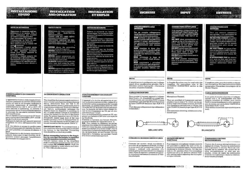
INPUT CONNECTIONS
3 input connections are on standard 3 pin XLR, 2 inputs are MIC, the
third input is mic/line switchable via the blue button on the back of the
unit marked mic/line input. For line operation (input 3 only) the blue
button is depressed.
• Line Input (Blue button depressed input 3 only).
Do not connect Pin1 to the shield of the XLR, as this will cause earth loops
and hum.
Unbalanced Balanced
Pin 1 Ground Pin 1 Ground
Pin 2 Signal Pin 2 Hot
Pin 3 Link to pin 1 Pin 3 Cold
• Mic Input (1,2 and with Blue button raised for input 3).
Balanced
Pin 1 Ground
Pin 2 Hot
Pin 3 Cold
• Phantom Power
Phantom power can be supplied to all mic inputs on pins 2 & 3 (12 V, 5
mA). For phantom power to be enabled the red button must be depressed.
ACCESSORIES
• LARX01 Loop test receiver
• LAFSM01 Loop field strength meter
• LAL01 Loop present stickers
• LACL10 Loop feeder cable
• LACF01 Feeder cable
Important information for correct disposal of the product in accordance with EC Directive 2002/96/EC This product
must not be disposed of as urban waste at the end of its working life. It must be taken to a special waste collection centre licensed by
the local authorities or to a dealer providing this service. Separate disposal of electric and/or electronic equipment (WEEE) will avoid
possible negative consequences for the environment and for health resulting from inappropriate disposal, and will enable the constituent
materials to be recovered, with significant savings in energy and resources. As a reminder of the need to dispose of this equipment
separately, the product is marked with a crossed-out wheeled dustbin.
Warranty This product is warranted to be free from defects in raw materials and assembly. The warranty period is governed by the applicable
provisions of law. Paso will repair the product covered by this warranty free of charge if it is faulty, provided the defect has occurred during normal
use. The warranty does not cover products that are improperly used or installed, mechanically damaged or damaged by liquids or the weather. If
the product is found to be faulty, it must be sent to Paso free of charges for shipment and return. This warranty does not include any others, either
explicit or implicit, and does not cover consequential damage to property or personal injury. For further information concerning the warranty
contact your local PASO distributor.
This product is in keeping with the relevant European Community Directives.
This manual suits for next models
2
Other Paso Amplifier manuals

Paso
Paso 3000 Series User manual

Paso
Paso PA8506-V User manual

Paso
Paso T3015DMA Technical Document

Paso
Paso AX3303 User manual

Paso
Paso AX3506 User manual

Paso
Paso AX8120 User manual

Paso
Paso DMS plus Series Technical Document

Paso
Paso PMW60-B User manual

Paso
Paso AX3032 User manual

Paso
Paso P 4060 E User manual
Popular Amplifier manuals by other brands

Martin Audio
Martin Audio MA2.8Q - SCHEMA manual

Cary Audio Design
Cary Audio Design SLP-88 Operation and installation manual

Gallien-Krueger
Gallien-Krueger 2001RB owner's manual

Boston Acoustics
Boston Acoustics LCAi220 owner's manual

Steren
Steren AMP-005 instruction manual

Mark Levinson
Mark Levinson 27.5 operating manual