2
LAX50
The loop consists of insulated cable between 0.5 mm and 1.5 mm CSA
(we recommend tri-rated switch gear wire, this has a much thicker jacket
and is easier to clip down as well as being harder wearing). The cable
should be securely clipped at either skirting level (taking adequate care
for protection when going past doorways) or at ceiling level (2.4m). Once
the loop cable is installed the ends should be bared and placed into the
orange loop connector on the top of the amplifier. The cable grip is
opened using a small flat blade driver. Conventionally the loop start is
connected to + and the end to .
MICROPHONES
Microphones should be placed near to the source of the sound for the
loop. No one microphone will fit all uses, PASO provide a variety of
microphones; in general the tie clip microphone will give good coverage
placed on the mullion of a counter or on the side of a television or monitor.
The desk microphone is particularly suited to desks, board room tables
and counters. Microphone cables must be run separately from the loop
cable, under no circumstances should the cables be tied together for any
distance, this will cause magnetic feedback and the unit will not perform
correctly. The microphones simply plug into the 3.5mm jack sockets on
the top of the amplifier.
TECHNICAL SPECIFICATIONS
Audio inputs 2 off
Type Microphone 3,5 mm mono jack
Phantom 4,5 V 1 mA
Sensitivity -50 dB
Mains input
Voltage 230 V ± 10% 50/60 Hz
Power 20 VA Max
Internal fuse F100 mA
Indications & Controls
Led indicators 2 off, power and loop current
User Controls Mix and Current Drive
Protection Recessed screwdriver adjust only
Audio Processing
Compressor Variable Ratio 1:1 to 20:1
Attack 10 ms
Release Automatic from 500 ms to 1500 ms
Noise reduction Yes, limits bandwidth to 8 kHz @ full
gain, 16 kHz @ -6 dB
Dynamic Range > 60 dB
THD < 0.5%
Output Stage
Type Current Mode
Loop impedance 0.1 Ωto 1 Ω
Peak Current 3.5 A Peak
125 ms Burst 3 A Peak
RMS Current 1.5 A (@ 1 kHz)
Protection Offset DC, Thermal, Short-circuit,
Soft Start
Dimensions
Extents 170 x 91 x 33 mm
User Controls Mix and Current Drive
Protection Recessed screwdriver adjust only
Via Mecenate, 90 - 20138 MILANO - ITALIA
TEL. +39-02-580 77 1 (15 linee r.a.)
FAX +39-02-580 77 277
http://www.paso.it
UDT- 12/02 - 11/576 - FC
S.p.A
NOTE
While thanking you for having chosen a PASO product, we would like
to remind you that our company works according to a certified Quality
System. This means that all our products are checked during every
phase of manufacturing in order to ensure that you will be fully satisfied
with your purchase. In any case, the guarantee will cover any
manufacturing flaws during the guarantee period. We recommend
that you read these instructions for use and follow them carefully in
order to exploit in full the performance of this product and use it
correctly.
PASO will not accept any liability for damage to property and/or
persons arising out of incorrect use of the equipment or of procedures
that do not comply with the instructions provided in this booklet.
PASO S.p.A. strive to improve their products continuously, and
therefore reserve the right to make changes to the drawings and
technical specifications at any time and without notice.
Notes
1. Loop coverage: the unit is rated at 30 m2coverage for a square room
(5.2 m a side) where the loop cable is fitted at ceiling (2.4 m) or
skirting board level. If the room is rectangular the unit will cover 50 m2
(10 m by 5 m) with the cable at ceiling or floor level. If the floor
contains a lot of steel (computer decking) or aluminium or the cable is
placed at a higher level than 2.4 m then the coverage will be reduced
(approximately 20% per additional metre in height).
2. If there is any doubt as to the construction of the building, it is always
best to lay a temporary loop in the approximate position the final loop
will occupy, this will determine the operation of the loop. Many new
buildings contain aluminium in lost screed flooring, loops placed on the
floor near this aluminium will fail to operate satisfactorily.
3. Microphone cables must be run separately from the loop cable,
under no circumstances should the cables be tied together for any
distance, this will cause magnetic feedback and the unit will not
perform correctly. Good practice is to twist the loop feeder cable
together between the start and end of the loop and the amplifier.
PASO provide the telecoils with twisted feeder cables, and feeder
cable is available in 5 m and 10 m lengths.
COMMISSIONING
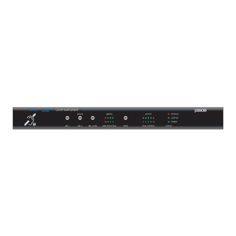
Before applying power to the unit ensure the drive control (middle of the
panel) is fully anti clockwise. Apply power, the green power LED should
illuminate. Next set the Mix control that balances the two MIC inputs
level. If only one is used then turn the control fully anti clockwise (input
1 used) or fully clockwise (input 2 used).
If both mics are in use set to the center position initially. Using a field
strength meter or loop listening device slowly turn the drive control
clockwise with someone speaking near the microphones positions
(alternatively a small radio or pink noise source giving 65 dBA output can
be used), the desired field strength is 0dB (100 mAM 1 ) at the center of
the room, or at head height in front of a counter using the telecoil.
As speech is being picked up the current LED should blink on the front of
the unit, if it does not blink, and field strength is not achieved, switch off
and check the wiring and loop continuity. Once the field strength has
been verified, the mix control can be adjusted to give the best balance if
multiple microphones are used. The check boxes on the front of the unit
can now be completed with the responsible persons name and contact
details (this should be the DDA officer for that section or the company
using the unit). It is good practice to provide a site with a loop listening
device so the responsible person can periodically test the installation and
log operation in a booklet. Your LAX50 should now be fully operational.
ACCESSORIES
LAC50 Telecoil
LAM50 Tie Clip Microphone
LASC50 Scart Adapter
