PCE Health and Fitness PCE-675 User manual

Non Contact Infrared Thermometer
User Manual PCE-675
Please read this user manual thoroughly before using this unit and keep it
properly for your future reference.

Contents
1. Introduction.................................................. 1
2. Features.........................................................1
3. Safety.............................................................2
4. Distance & Spot Size......................................3
5. Specifications................................................ 5
6. Meter Description......................................... 7
7. LCD Display Description................................ 8
8. Operating Instruction.................................... 9
9. Measurement Mode................................... 12
10. Emissivity..................................................... 16
11. Notes........................................................... 18
12. Accessories.................................................. 19
13. Warraanty.....................................................20

1
1. Introduction
Congratulations on purchasing our professional non-contact
infrared thermometer. This product is a professional, hand-held
meter for non-contact Infrared temperature measurement that is
simple to use, highly accurate, and has a wide temperature range.
It can be used to measure the surface temperature of
hard-to-reach or moving objects.
2. Features
Accurate and fast non-contact measurements
13 in-built 13 laser pointers increase the target accuracy
Multifunction thermometer for k-type temperature, surface
temperature, ambient temperature, ambient humidity, dew
point temperature and wet bulb temperature
UV light for leak detection
LED light to enable working in dark environments
Temperature difference alarm with audible and visual alarm
Large color LCD display with backlight
°C / °F selection
2
Low power indication
Auto power off.
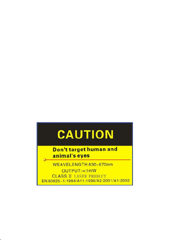
3. Safety
Use with extreme caution when the laser beam is turned on.
Do not point the beam towards eye of anyone or any animals.
Do not allow the beam to strike the eye from a reflective
surface.
Do not use the laser near explosive gases.

3
4. Distance & Spot Size
When the distance (D) between the thermometer and the
object increases, the light spot (S) increases. The distance to
the spot ratios are shown below in the field of view diagram.
Note:

4
Notes:
Accuracy can be ensured while the temperature is at 18℃to
28℃(64℉~82℉) and humidity is less than 80 % RH.
Make sure the target is larger than the unit’s spot size. The
smaller the target, the closer you should be to it. When
accuracy is critical, make sure the target is at least twice as
large as the spot size.

5
5. Specifications
Temp. range (IR)
-50℃~550℃/-58℉~1022℉
D:S
13:1
IR Accuracy
-50~0℃/ -58~32℉:±3℃/ 5.4℉
>0℃:±1.5% or ±2.0 / 3.6℉whichever is greater
Emissivity
Adjustable from 0.1~1.0
Resolution
0.1℃(0.1℉)﹤1000 ,1℃(1℉)﹥1000
Response Time
﹤500ms
Spectral Response
8~14um
Diode Laser
Output<1mW,630~670nm, class 2(Ⅱ) laser
Range(TK)
-50℃~850℃/ -58℉~1562℉
TK Accuracy
±1.5% or ±1.5 / 2.7℉whichever is greater
Resolution
0.1℃(0.1℉)﹤1000 ,1℃(1℉)﹥1000
Ambient Temp.
Range
-20℃~60℃/ -4℉~140℉
Accuracy
0℃~40℃/ 32℉~104℉: ±1.0℃/ 1.8℉
Others: ±2.0℃/ 3.6℉
Resolution
0.1℃/ 0.1℉
Ambient Humidity
Range
0~100%RH
Accuracy
35~75%RH: ±3.0%RH
other; ±5.0%RH

6
Resolution
1%RH
Dew Point Temp.
Range
-20~60℃/ -4~140℉
Accuracy
±1.5℃/ 2.7℉(25℃/ 77℉, 40~80%RH)
Resolution
0.1℃/ 0.1℉
Wet-bulb Temp.
Range
-20~60℃/ -4~140℉
Accuracy
±1.5℃/ 2.7℉(25℃/ 77℉,40~80%RH)
Resolution
0.1℃/ 0.1℉
Auto Power Off
Meter shuts off automatically after around one minute
of inactivity
Operation Temp.
0℃~ 50℃/ 32℉to 122℉
Storage Temp.
-20℃~70℃/ -4℉to 140℉
Relative Humidity
Operating:10 to 95%RH
Storage:<80%RH
Power Supply
1*9V battery
7
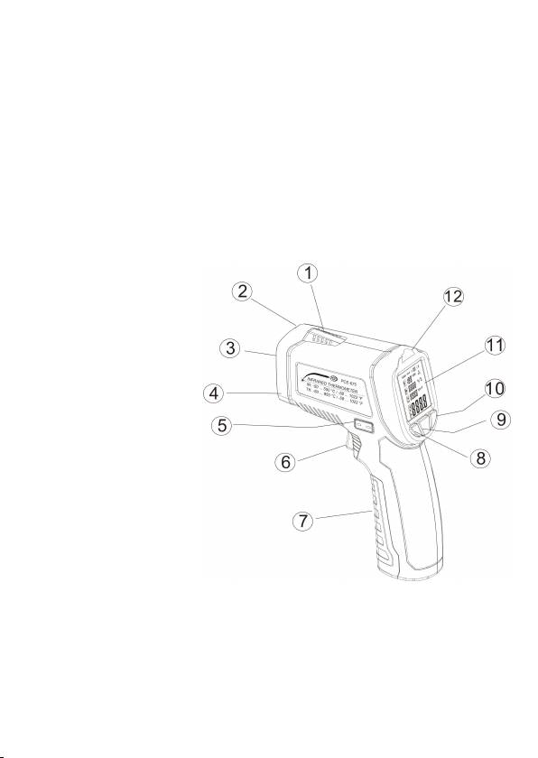
6. Meter Description
1) Temperature and humidity sensor
2) Laser pointer
3) IR sensor
4) Flashlight, UV Light
5) K-type probe interface
6) Trigger button
7) Battery Compartment
8) Light On/Off key
9) MODE key
10) Laser On/Off key
11) LCD display screen
12) Alarm indicator

8
7. LCD Display Description
1) Measurement and Data hold
2) Ambient humidity symbol and reading
3) Ambient temperature symbol and reading
4) Dew point temperature symbol
5) Wet bulb temperature symbol
6) Infrared temperature symbol
7) Wet bulb and IR temperature reading
8) Dew point and K-type Temp reading
9) K type temperature symbol
10) Temperature unit symbol
11) Humidity unit symbol
12) Laser symbol
13) Emissivity
14) Battery level

9
8. Operating Instruction
8.1 Operating steps:
a) Hold the meter by its handle grip and point it toward the
surface to be measured.
b) Pull and hold the Trigger to turn the meter on, the "SCAN"
icon will appear and begin testing.
c) Release the trigger, the "HOLD" icon will appear, the
readings will be frozen
d) The meter will automatically shut off after 1 minute of
inactivity.
Measurement Note:
If the meter used in an ambient temperature with a large
temperature change, wait it at least 30 minutes to adjust it.
The laser is designed for aiming only; it can be shut off while
operating in short distance to save the battery.
8.2 Button Function
(1) Key
a) In HOLD mode, pressing MODE key will enter into the

10
Mildew alarm mode, Temperature difference alarm mode,
Environment detection mode, K-type temperature mode
and Emissivity adjustment mode in turn.
b) In HOLD mode, long pressing the MODE key can switch
temperature unit ℃or ℉.
(2) Key
Pressing the flashlight key will momentarily turn on/off the
flashlight. Press and hold to turn on/off the UV light.
(3) Key
Pressing the laser key will momentarily can turn on/off the laser.
8.3 Battery Replacement
When the low battery icon “ ”appears, replace the meter's
battery.
Open the battery compartment, replace a new 9V battery and
then close the battery compartment cover.

11

12
9. Measurement Mode
9.1 Mildew Alarm Mode
After powering on the meter, press the MODE key to switch to the
Mildew alarm mode, the LCD will display as below fig. 1. Press and
hold the trigger button, the LCD will display the current measuring
ambient humidity, ambient temperature, dew point temperature
and surface temperature. The scanned surface temperature will
be compared with the dew point temperature automatically to
determine whether the target object is mildewed. The LED color
will turn Green if it’s not mildewed. The LED color will turn Red if
it’s already been mildewed. The LED color will turn Yellow if it’s on
the verge of mildew.
(Fig. 1)
13
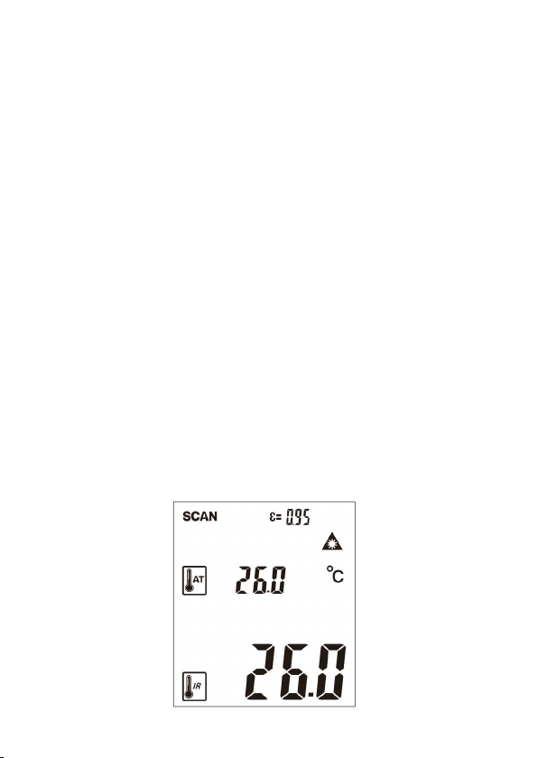
9.2 Temperature Difference Alarm Mode
After powering on the meter, press MODE key to switch to the
Temperature difference alarm mode, the LCD will display as below
fig. 2. Press and hold the trigger button, the LCD will display the
current measuring ambient temperature and surface temperature.
The scanned surface temperature will be compared with the
ambient temperature automatically to determine whether the
target object is working properly. The LED color will turn Green if
the scanned surface temperature is close to the ambient
temperature. The LED color will turn Red if the scanned surface
temperature is above around 5℃higher or lower than the
ambient temperature. The LED color will turn Yellow if the
scanned surface temperature is above around 3℃higher or lower
than the ambient temperature.
(Fig. 2)
14
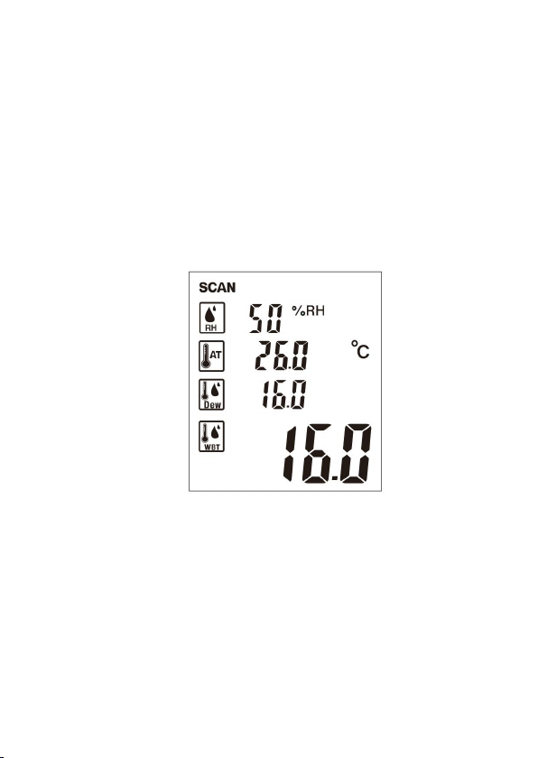
9.3 Environment Detection Mode
After powering on the meter, press MODE key to switch to the
Environment detection mode, the LCD will display as below fig. 3.
Press and hold the trigger button, the LCD will display the current
measuring ambient humidity, ambient temperature, dew point
temperature and wet-bulb temperature simultaneously.
(Fig. 3)
9.4 K-type Temperature Mode
After powering on the meter, press MODE key to switch to the
K-type temperature mode, the LCD will display as below fig. 4.
Insert a K-type thermocouple probe into the probe socket. Press
and hold the trigger button, the LCD will display the current
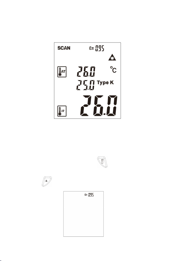
15
measuring ambient temperature, K-type temperature and surface
temperature simultaneously.
(Fig. 4)
9.5 Emissivity Set
After power on the meter, press MODE key to switch to the
Emissivity set mode, the LCD will display as below fig. 5. In the
emissivity adjustment mode, press key to increase the value
and press key to decrease the value.
(Fig. 5)

16
9.6 UV light
The UV light could be used for fluorescent leak detection to find
all system leaks quickly and easily.
Fluorescent leak detection:Add or inject the fluorescent agent
into the system and let it circulate with host fluid. Once circulation
is completed, use UV light to inspect for leak sites. The agent will
be fluorescent by the UV light, so that we can locate the leak sites.
10. Emissivity
The emissivity of the surface of a material is its effectiveness in
emitting energy as thermal radiation. It is the ratio of the thermal
radiation from a surface to the radiation from an ideal black
surface at the same temperature. The ratio varies from 0 to 1. The
bigger the ratio, the stronger the thermal radiation is from the
surface. The emissivity of surface of most materials is between
0.85~0.98. The default emissivity of this unit is set at 0.95;
however, it can be adjustable. Before measuring, please adjust it
to the suitable emissivity according to below table.

17
Emissivity Table
Substance
Thermal
emissivity
Substance
Thermal emissivity
Aluminum
0.30
Glass
0.90 to 0.95
Asphalt
0.95
Iron oxides
0.78 to 0.82
Concrete
0.95
Lacquer
0.80 to 0.95
Asbestos
0.95
Plastic
0.85 to 0.95
Ceramic
0.95
Paper
0.70 to 0.94
Copper
0.50
Sand
0.90
Brick
0.90
Rubber
0.95
Carbon
0.85
Timber
0.94
Fat-lute
0.94
Textiles
0.94
Frozen food
0.90
Lead
0.50
Hot food
0.93
Marble
0.94
Ice
0.98
Cloth black
0.98
Snow
0.90
Plaster
0.8 0to 0.90
Human skin
0.98
Water
0.93

18
11. Notes
(1) Working principle
The infrared thermometer is designed for measuring
surface temperature of an object.
The optical sensor can emit, reflect and transmit energy,
which is collected and focused on a detector, then
translate it into the temperature reading by electronics
and displayed on the LCD screen.
The laser is used for aiming the target object only.
(2) Field of View
The object under test should be larger than the spot size
calculated by the field of view diagram.
The smaller the target object is, the closer the meter
should be to it for accurate measuring.
When accuracy is critical, make sure the target is at least
twice as large as the spot size.
(3) Distance& Spot Size
As distance (D) from the object increases, the spot size (S) of
the area measured by the unit becomes larger.
Table of contents
Other PCE Health and Fitness Thermometer manuals

PCE Health and Fitness
PCE Health and Fitness PCE-EV-KIT 3 User manual

PCE Health and Fitness
PCE Health and Fitness PCE-600 User manual

PCE Health and Fitness
PCE Health and Fitness 4250348700308 User manual

PCE Health and Fitness
PCE Health and Fitness PCE-TC 24 User manual

PCE Health and Fitness
PCE Health and Fitness PCE-313A-ICA User manual

PCE Health and Fitness
PCE Health and Fitness PCE-HPT 1 User manual

PCE Health and Fitness
PCE Health and Fitness PCE-HT 50 User manual

PCE Health and Fitness
PCE Health and Fitness CMM 10 User manual

PCE Health and Fitness
PCE Health and Fitness PCE-893 User manual

PCE Health and Fitness
PCE Health and Fitness PCE-IR 425 User manual


