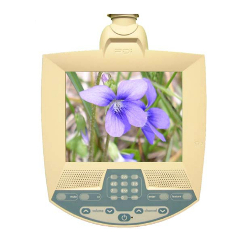
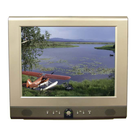
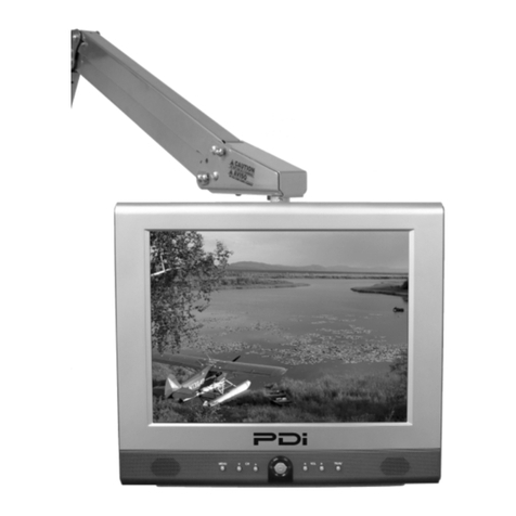
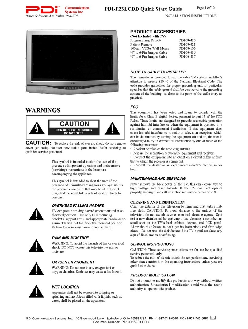
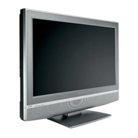
PDi PDI-P15LCDB-ARM User manual

PDI-P15LCDB User Manual
Document Number: PD196-096 Rev 2
- 1 -
User
Manual
Communication
Systems, Inc.
40 Greenwood Lane
Springboro, Ohio
45066
PH: 937-743-6010
FX: 937-743-5664
http://www.pdiarm.com
PDI-P15LCDB-ARM
&
PDI-P15LCDB-WR
Model PDI-P15LCDB
LCD TV
Computer Monitor
Better Solutions Are Within Reach®

PDI-P15LCDB User Manual
Document Number: PD196-096 Rev 2
- 2 -
WARNINGS
WARNING
RISK OF ELECTRIC SHOCK
DO NOT OPEN
WARNING:
To reduce the risk of electric shock, do not remove cover (or back). No
user serviceable parts inside. Refer servicing to qualified service
personnel.
This lightning flash with arrowhead symbol, within an equilateral is
intended to alert the user of the presence of uninsulated “dangerous
voltage” within the product’s enclosure that may be of sufficient
magnitude to constitute a risk of electric shock to persons.
The exclamation point within an equilateral triangle is intended to alert
the user of the presence of important operating and maintenance
(servicing) instructions in the literature accompanying the appliance.
NOTE TO CABLE TV INSTALLER
This reminder is provided to call the cable TV systems installer’s
attention to Article 820-40 of the National Electrical Code. The code
provides guidelines for proper grounding and, in particular, specifies that
the cable ground shall be connected to the grounding system of the
building, as close to the point of the cable entry as practical.
MAINTENANCE AND SERVICING
Never remove the back cover of the TV, this can expose you to high
voltage and other hazards. If the TV does not operate properly, unplug it
and call an authorized service center or PDI.
CLEANING
Clean the exterior of this television by removing dust with a lint-free
cloth.
RAIN AND MOISTURE
WARNING: To avoid the hazards of fire or electrical shock, DO NOT
expose this television to rain or moisture.
OXYGEN ENVIRONMENT
WARNING: Do not use in any oxygen tent or oxygen chamber. Such
use may cause a fire hazard.
WET LOCATION
Apparatus shall not be exposed to dripping or splashing and no objects
filled with liquids, such as vases, shall be placed on the apparatus.

PDI-P15LCDB User Manual
Document Number: PD196-096 Rev 2
- 3 -
PRODUCT MODIFICATION
Do not attempt to modify this product in any way without written
authorization. Unauthorized modification could void the user’s authority
to operate this product.
POWER
Arm Mounted
This set operates from a PDI-771-LCD power supply when arm
mounted. The supply is housed in the support arm wall bracket.
a. Connect the arm power cord that exits the base of the support
arm.
b. Connect the power cord to an AC outlet.
c. Connect the hospital CATV coax. NOTE: Do not connect to a
powered coax! Damage will result to the TV.
Wall Mounted
The wall mount version is powered using an external brick style power
supply mounted to the wall bracket.
In the event of thunderstorms or power outages, please unplug the AC
plug from the wall outlet and unplug the cable TV coax. Do not allow
anything to rest upon or roll over the power cord, and do not place the
set where the power cord is subject to damage.
REGULATORY INFORMATION
FCC
This equipment has been tested and found to comply with the limits for a
Class B digital device, pursuant to part 15 of the FCC Rules. These
limits are designed to provide reasonable protection against harmful
interference when the equipment is operated in a residential or
commercial installation. If this equipment does cause harmful
interference to radio or television reception, which can be determined by
turning the equipment off and on, the user is encouraged to try to correct
the interference by one or more of the following measures:
• Reorient or relocate the receiving antenna.
• Increase the separation between the equipment and receiver.
• Connect the equipment into an outlet on a circuit different from
that to which the receiver is connected.
• Consult the dealer or an experienced radio/TV technician for
help.
UNDERWRITERS LABORATORIES
This device is safety tested and listed by the Underwriters Laboratories
as a product for use in both the United States and Canada.
CATV COAX

PDI-P15LCDB User Manual
Document Number: PD196-096 Rev 2
- 4 -
IMPORTANT SAFETY INSTRUCTIONS
11. Only use attachments/accessories specified
by the manufacturer.
12. Use only with the cart,
stand, tripod, bracket or
table specified by the
manufacturer, or sold with
the apparatus. When a
cart is used, use caution
when moving the
cart/apparatus
combination to avoid
injury from tip-over.
1. Read these instructions.
2. Keep these instructions.
3. Heed all warnings.
4. Follow all instructions.
5. Do not use this apparatus near water.
6. Clean only with dry cloth.
7. Do no block any ventilation openings.
Install in accordance with the
manufacturer’s instructions.
8. Do not install near any heat source such
as radiators, heat registers, stove, or other
apparatus (including amplifiers) that
produce heat.
9. Do not defeat the safety purpose of the
hospital grounding-type plug. A hospital
plug has two blades and a third grounding
prong. The third prong is provided for
your safety. If the provided plug does not
fit into your outlet, consult an electrician
for replacement of the obsolete outlet.
10. Protect the power cord from being walked
on or pinched particularly at plugs,
convenience receptacles, and the point
where they exit from the apparatus.
13. Unplug this apparatus during lightning
storms or when unused for long period of
time.
14. Refer all servicing to qualified service
personnel. Servicing is required when the
apparatus has been damaged in any way,
such as power-supply cord or plug is
damaged, liquid has been spilled or objects
have fallen into the apparatus, the
apparatus has been exposed to rain or
moisture, does not operate normally, or has
been dropped.
Copyright, Disclaimer, and Trademarks
COPYRIGHT
PDI Communication Systems, Inc. claims proprietary right to the material disclosed in this user
manual. This manual is issued for user information only and may not be used to manufacture
anything shown herein. Copyright by PDI Communication Systems, Inc. All rights reserved.
DISCLAIMER
The author and publisher have used their best efforts in preparing this manual. PDI
Communication Systems, Inc. make no representation or warranties with respect to the accuracy
or completeness of the contents of this manual and specifically disclaim any implied warranties or
merchantability or fitness for any particular purpose and shall in no event be liable for any loss of
profit or any other damages. The information contained herein is believed accurate, but is not
warranted, and is subject to change without notice or obligation.
TRADEMARKS
All brand names and product names used in this manual are trademarks, registered trademarks,
or trade names of their respective holder. PDI and Better Solutions Are Within Reach are
registered trademarks of PDI Communication Systems, Inc., Springboro, Ohio.

PDI-P15LCDB User Manual
Document Number: PD196-096 Rev 2
- 5 -
Contents
WARNINGS------------------------------------------------------------------------------------------------------------- 2
IMPORTANT SAFETY INSTRUCTIONS ----------------------------------------------------------------------- 4
Copyright, Disclaimer, and Trademarks--------------------------------------------------------------------------- 4
Contents ------------------------------------------------------------------------------------------------------------------ 5
Supplied Accessories --------------------------------------------------------------------------------------------------- 6
Arm Installation -------------------------------------------------------------------------------------------------------- 7
Wall Installation -------------------------------------------------------------------------------------------------------- 9
Remote-------------------------------------------------------------------------------------------------------------------12
Controls------------------------------------------------------------------------------------------------------------------13
Connections-------------------------------------------------------------------------------------------------------------13
Menu Tree---------------------------------------------------------------------------------------------------------------17
Programming Channels ----------------------------------------------------------------------------------------------19
Picture -------------------------------------------------------------------------------------------------------------------20
Sound---------------------------------------------------------------------------------------------------------------------21
Special--------------------------------------------------------------------------------------------------------------------23
Parental Control -------------------------------------------------------------------------------------------------------26
MPAA Rating ----------------------------------------------------------------------------------------------------------27
Service Setup -----------------------------------------------------------------------------------------------------------29
Radio Control ----------------------------------------------------------------------------------------------------------31
Picture Setup in PC Mode -------------------------------------------------------------------------------------------32
Product Specifications ------------------------------------------------------------------------------------------------33
Troubleshooting--------------------------------------------------------------------------------------------------------34
Model PDI-P15LCDB TV Limited Warranty--------------------------------------------------------------------35

PDI-P15LCDB User Manual
Document Number: PD196-096 Rev 2
- 6 -
Supplied Accessories
The follow accessories are provided with the Product.
1. AC Cord (Wall Mount Model Only) 2. AC/DC Adaptor (Wall Mount Model Only)
3. Owner’s Manual 4.Pillow Speaker Cable (Wall Mount Model Only)
5. Brackets (Wall Mount Model Only)

PDI-P15LCDB User Manual
Document Number: PD196-096 Rev 2
- 7 -
Arm Installation
LOCATION GUIDELINES
The PDI-P15LCDB-ARM TV is intended for entertainment purposes and should be installed in a
non-hazardous area in accordance with the National Electrical Code (NEC), ANSI/NFPA 70.
The PDI-P15LCDB-ARM TV is designed to be mounted and supported on either a PDI 405 or
500 series support arm. Select a location that is near an AC wall outlet and that does not expose
the TV to bright room lights or sunlight if possible.
CABLE SYSTEM GROUNDING
The coax cable system connected to the PDI-P15LCDB-ARM TV should be grounded in
accordance with the National Electrical Code, ANSI/NFPA 70. The code provides guidelines for
proper grounding and, in particular, specifies that the cable ground shall be connected to the
grounding system of the building, as close to the point of the cable entry as practical.
SUPPORT ARM
The PDI-P15LCDB-ARM is designed to mount to either a 405 or 500 series support arm that is
pre-strung with an LCD power cable and RF coax cable. Computer display functionality requires
an arm pre-strung with a compatible VGA computer cable.
Attach Monitor to Arm
a. Fasten mounting plate “A” to mounting
channel “B” using (4) #10 flat washers
and (4) 10-32 nylock hex nuts
provided.
b. Connect the Antenna cable to the
“ANT.”
c. Connect the power cable to “DC 12V”.
d. For computer operation connect
computer VGA cable to “PC/DTV IN”
and audio cable to “PC AUDIO IN”.
Cable Cover
a. Position cable cover “C” into mounting
channel “B”.
b. Attach cable cover with (4) #8x32
screws.
A
B
C
B

PDI-P15LCDB User Manual
Document Number: PD196-096 Rev 2
- 8 -
Align Bottom Cover
a. Insert studs “D” into slots “E”,
being careful to not pinch any
wires.
Attach Bottom Cover
a. Align (4) holes in “B” and “C”.
Install (4) 10-32 x 3/8 Phillips head
machine screws.
Power and Signal Connections
1. Connect the ARM POWER CABLE
that exits the base of the arm to the
power connector on the bottom of the
power supply.
2. Connect the CATV RF CABLE to the
hospital’s cable system. NOTE: Do
not connect to a powered coax!
Damage will result to the TV.
3. Plug the AC Plug to the wall outlet.
E
D
AC PLUG
Wall Outlet
CATV RF
CABLE
ARM
POWER
CABLE

PDI-P15LCDB User Manual
Document Number: PD196-096 Rev 2
- 9 -
Wall Installation
LOCATION GUIDELINES
The PDI-P15LCDB-WR TV is intended for entertainment purposes and should be installed in a
non-hazardous area in accordance with the National Electrical Code (NEC), ANSI/NFPA 70.
The PDI-P15LCDB-WR is capable of being mounted with several commercially available
mounting brackets utilizing the 100 mm VESA hole pattern. The PDI-P15LCDB-WR TV is able to
be wall mounted at the foot of a patient’s bed with the supplied bracket. Select a location that is
near a AC wall outlet and that does not expose the TV to bright room lights or sunlight if possible.
The LCD TV also requires connection of both CATV cable signal and across-room wiring for the
pillow speaker.
OSHPD (State of California Only)
The combined weight of the PDI-P15LCDB-WR TV, wall mount, and power supply totals less
than 20 pounds. At the time of this writing, the involvement of a written, submitted, reviewed, and
approved plan by OSHPD is not required to install the PDI-P15LCDB TV in the state of California.
However, the installer and architect in charge should verify current regulatory compliance.
CABLE SYSTEM GROUNDING
The coax cable system connected to the PDI-P15LCDB-WR TV should be grounded in
accordance with the National Electrical Code, ANSI/NFPA 70. The code provides guidelines for
proper grounding and, in particular, specifies that the cable ground shall be connected to the
grounding system of the building, as close to the point of the cable entry as practical.
WALL MOUNTING THE LCD TV WITH THE SUPPLIED BRACKET
1. Select a location on the wall
approximately 7 inches below the
ceiling. Position the Wall Bracket and
locate two mounting holes. Secure the
bracket to the wall (mounting hardware
is not included).
2. Position the Back Mount on the LCD
TV cabinet. Attach with four M4
screws provided.
3. Mate the Back Mount to the Wall
Bracket making sure the pivot bolts are
retained in the “L” shaped slot.
Secure with two 10x32 pilfer screws.
4. Slide the Power Pack into the metal
holster. Connect the DC Power Plug
into the “DC 12V” connector on the
back of the TV.
Connect the AC line cord.
5. The TV’s tilt can be adjusted by
loosening both Pilfer Screws, adjusting
tilt, and then tighten.
13 3/4” Vert x 15 1/2” Horiz
7”
Wall Bracket
NOT TO SCALE
A
C
CROSS-ROOM
& CATV SIGNAL
WIRING

PDI-P15LCDB User Manual
Document Number: PD196-096 Rev 2
- 10 -
Installation Exploded View
Power Pack
Back Mount
M4 Screws (4)
Wall Bracket
Pilfer Screws (2)

PDI-P15LCDB User Manual
Document Number: PD196-096 Rev 2
- 11 -
ACROSS-ROOM WIRING
A ¼” stereo style pillow speaker (pendant control) jack is located on the TV’s connector panel on
the backside. The PDI-P15LCDB is designed to work with either a digital pillow speaker or a
single-button analog (switch-style) pillow speaker. The PDI-P15LCDB also supports certain style
pillow speakers with a number pad for direct channel access. The following pillow speakers have
been tested with the PDI-P15LCDB. Please contact the pillow speaker vendor directly for an
additional listing of models and available options.
Make Analog Digital Digital Direct Access
Curbell 3103-001 3D0103096000ZM0-001 D0108-A0Z-R0001
Medtek A1833-087 A1871-085T A1552-087D, A1871-087D,
Crest XL031E0AXXXZ1N1
XL031E1AJ00Z1N1
XL031X0AXXXZ1N1
XL031X1AJ00Z1N1
Use type SJ cord or better for the across room wiring between the TV and the bedside pendant
control. A pin-out is provided below.
WARNING: DO NOT connect the pillow speaker circuit Common to earth ground.
Grounding of the Common will defeat the isolation circuitry of the PDI-P15LCDB
and possibly expose the patient to harmful shock currents should a wiring fault
occur.
CAUTION Installer. This product is not provided with a pendant control. It is
expected that the institution (or hospital) will provide one for attachment to the
Pillow Speaker Jack on the back of the TV. As part of the installation,
examine the pendant control to verify whether a marking similar to the one
below appears on it:
‘CAUTION – Risk of fire if used in oxygen-enriched atmosphere – return to
hook or holder after use.’
SPEAKER
DATA / SWITCH
COMMON
SPEAKER
DATA / SWITCH
COMMON
Jumper Supplied
with TV
Optional Jumper
ACROSS ROOM WIRING

PDI-P15LCDB User Manual
Document Number: PD196-096 Rev 2
- 12 -
Remote
BATTERY INSTALLATION
1. Pull the battery cover upward in the
arrow direction to remove.
2. Insert two “AAA” batteries. Observe
the correct polarity.
3. Replace the battery cover.
USING THE REMOTE
1. Make sure there are no objects between the remote control and its sensor.
2. Don’t store the remote control near a heater or damp place.
3. A strong impact to the remote control may cause damage and operational failure to the
remote.
4. Fluorescent lights, sunlight, or other strong light directed on the front of the TV may
interrupt the remote signal. In this case, position the TV away from the light in another
direction to restore operation of the remote control.
FUNCTIONS
All TV functions can be controlled using the remote control. Some functions can also be adjusted
with the buttons on the front panel of the set.
POWER
123
5
46
789
0
MENU TV/AV
ST/SAP
SLEEP Q.VIEW LIST
CH▲
CH▼
◄VOL VOL►
OK
PSM SSM PC/ *
CC
Sets the closed captions.
CH▼▲
Selects a next channel or a
menu item.
OK
A
ccepts your selection or
displays the current mode.
MENU
Displays an on-screen menu
ST/SAP
A
djusts the MTS-Stereo, Mono,
Second Audio Program (SAP).
SLEEP
Sets the sleep timer.
PSM(Picture Status Memory)
Recalls your preferred picture
setting.
A
RC / *
CC MEMORY
POWER
Turns the TV On or Off.
MUTE
Turns the sound on or off.
TV/AV
Selects COMPONENT, VIDEO, S-VIDEO,
RADIO, PC, DTV, or TV mode. Clears the
menu from the screen.
Q.VIEW
Returns to the previously viewed
channel.
MEMORY
Stores or deletes the current channel
from memory.
PC/*
Selects PC mode.
SSM(Sound Status Memory)
Recalls your preferred sound setting.
VOL◄►
A
djusts the sound level.
A
djusts menu settings.
LIST
Displays the Program List menu.
ARC/*
Selects ARC mode.

PDI-P15LCDB User Manual
Document Number: PD196-096 Rev 2
- 13 -
Controls
1. CC – Sets the Closed Caption mode.
2. ▼CH ▲– Selects a TV channel or a MENU item when the on screen menu is active.
3. POWER – Turns the TV On and Off. Illuminates red when the TV is Off. Illuminates
green when the TV is On. Flashes when a IR remote control signal is detected by the
TV.
4. ◄VOL ►- Adjusts the internal TV speaker or headphone volume up or down. Also
adjusts a selected menu item when the on screen menu is active.
5. TV/AV – Selects either TV, VIDEO, S-VIDEO, RADIO (only if Radio is activated via the
Setup Menu). The TV/AV button can be disabled using the remote control to prevent
patient and visitor tampering – see the “Special” menu and “Lock” instructions elsewhere
in this manual for details.
Connections
Connection Panel
The connection panel is located on the back of the TV and provides connections to external
equipment.
1. DC 12V – Power Input Jack.
2. PILLOW – Pillow Speaker Jack.
3. COMM – CCI / Cloner Port.
4. PC-AUDIO IN – PC Audio Input Jack.
5. PC-ANALOG – Computer Video Input D-Sub Jack.
6. S-VIDEO – Input connection for S-Video signal.
7. A/V IN – Video and audio input jacks.
8. ANT – Hospital Cable TV Input.
ANT
S-VIDEO
DC 12V
VIDEO L(MONO)R
PC-AUDIO IN
A
/V IN
COMM
PILLOW PC-ANALOG
1 2 3 4 5 6 7 8
▼CH ▲ ◄
V
OL ►CC TV/A
V
1 2 3 4 5

PDI-P15LCDB User Manual
Document Number: PD196-096 Rev 2
- 14 -
ANT.
Connect the hospital’s cable signal to this fitting.
CAUTION: Some hospital cable systems provide power voltage
on the coaxial cable. The P15LCDB is NOT designed to be
powered over a coaxial cable. Do NOT connect to a powered
coaxial cable. Damage will result to the TV.
A/V IN (VCR, DVD, Game Box, etc)
1. Connect the audio outputs from the device’s (L, R) to the A/V IN on the TV.
Connection is color coded.
2. Connect the video output from the device to the A/V IN on the TV.
Connections are color coded.
3. Select VIDEO mode by pressing the TV/AV button repeatedly.
The TV/AV button can be disabled using the remote control to prevent patient and visitor
tampering – see the “Special” menu and “Lock” instructions elsewhere in this manual for
details.
Operate the device and check for a displayed picture with sound.
ANT
S-VIDEO
DC 12V
VIDEO L(MONO)R
PC-AUDIO IN
A
/V IN
COMM
PILLOW PC-ANALOG
VCR, DVD, Game Box
ANT
S-VIDEO
DC 12V
VIDEO L(MONO)R
PC-AUDIO IN
A
/V IN
COMM
PILLOW PC-ANALOG

PDI-P15LCDB User Manual
Document Number: PD196-096 Rev 2
- 15 -
S-VIDEO (VCR or DVD)
Many VCR’s & DVD’s provide S-Video signals to provide improved picture quality.
1. Connect the S-VIDEO output to the S-VIDEO input on the TV.
2. Connect the audio cables to the L(MONO) R A/V IN inputs of the TV.
3. Select S-VIDEO mode by pressing the TV/AV button repeatedly. The TV/AV button can
be disabled using the remote control to prevent patient and visitor tampering – see the
“Special” menu and “Lock” instructions elsewhere in this manual for details.
Press the PLAY button on the VCR or DVD.
COMPUTER
The PDI-P15LCDB is designed to also be used as a computer monitor. NOTE: If mounted on a
support arm, the arm must be pre-strung with a compatible VGA computer cable to utilize this
feature.
1. Connect the VGA computer cable to the PC-ANALOG jack on the set.
2. Connect the PC Audio In cable from the PC to the PC AUDIO IN of the set.
3. Press the TV/AV button to select PC mode. The TV/AV button can be disabled using the
remote control to prevent patient and visitor tampering – see the “Special” menu and
“Lock” instructions elsewhere in this manual for details.
4. Switch on the PC. The PC screen should appear on the set.
S-VIDEO VCR or DVD
ANT
S-VIDEO
DC 12V
VIDEO L(MONO)R
PC-AUDIO IN
A
/V IN
COMM
PILLOW PC-ANALOG
COMPUTER
ANT
S-VIDEO
DC 12V
VIDEO L(MONO)R
PC-AUDIO IN
A
/V IN
COMM
PILLOW PC-ANALOG

PDI-P15LCDB User Manual
Document Number: PD196-096 Rev 2
- 16 -
MODE RESOLUTION HORIZONTAL
FREQUENCY (Khz)
VERTICAL
FREQUENCY (Hz)
VGA
640x480
640x480
640x480
720x400
31.5 Khz
37.9 Khz
37.5 Khz
31.4 Khz
60 Hz
72 Hz
75 Hz
70 Hz
SVGA
800x600
800x600
800x600
800x600
35.1 Khz
37.9 Khz
48.1 Khz
46.9 Khz
56 Hz
60 Hz
72 Hz
75 Hz
XGA
1024x768
1024x768
1024x768
48.4 Khz
56.5 Khz
60.0 Khz
60 Hz
70 Hz
75 Hz
DTV
720 x 480p
720 x 576p
1280 x 720p
1280 x 720p
1920 x 1080i
1920 x 1080i
31.5 Khz
31.2 Khz
45.0 Khz
37.5 Khz
33.7 Khz
28.1 Khz
60 Hz
50 Hz
60 Hz
50 Hz
60 Hz
50 Hz
NOTE:
1. If the set is cold, there may be a small “flicker” when the set is switched ON.
This is normal, there is nothing wrong with the set.
2. Some dot defects may appear on the screen, like Red, Green or Blue spots. However,
this will have no impact or effect on the monitor performance.
COMM
The “COMM” port provides interconnectivity to 2nd part control boxes including the PDI cloner
(model PD108-311). Please refer to the device’s specific instructions for details.
ANT
S-VIDEO
DC 12V
VIDEO L(MONO)R
PC-AUDIO IN
A
/V IN
COMM
PILLOW PC-ANALOG
PDI
PD108-311

PDI-P15LCDB User Manual
Document Number: PD196-096 Rev 2
- 17 -
Menu Tree
The on screen menus are navigated by first pressing the MENU
button on the remote and then using the CH ▲▼ button to
select the desired menu.
Equalizer
Position: ▲▼ Adjust : ◄►
Back : MENU Exit : TV/AV
▄
▄▄▄▄
▄
▄▄▄▄
▄
▄▄▄▄
0.1 0.5 1.5 5.0 10Khz
Flat
Music
Movie
Speech
User
Parental Control
TV Rating ►
MPAA Rating ►
Block Hour Always
Parental Lock ON
Change Password ►
Position: ▲▼ Next: ◄►
Back : MENU Exit : TV/AV
Clock
Clock --:--
Off Time --:-- Off
On Time --:-- Off
On Program 0
Position: ▲▼ Adjust : ◄►
Back : MENU Exit : TV/AV
Setup
A
uto Program ►
Manual Program ►
Language ►
Parental Control ►
Caption Off
Position: ▲▼ Next: ◄►
Back : MENU Exit : TV/AV
Special
Clock ►
Blue Back Off
A
uto Sleep Off
Lock Off
Radio Off
A
uto Power on Off
Power Management Off
Bed A/B A
Position: ▲▼ Next: ◄►
Back : MENU Exit : TV/AV
Sound
Equalizer ►
Balance 0
A
VL Off
Surround Off
Sound Mode MONO
Minimum Volume 0
Maximum Volume 100
Power On Volume LAST
Internal Speaker OFF
Position: ▲▼ Next: ◄►
Back : MENU Exit : TV/AV
Picture
Contrast 90
Brightness 75
Color 75
Sharpness 60
Tint 0
Position: ▲▼ Adjust: ◄►
Back : MENU Exit : TV/AV
MAIN MENU
Picture ►
Sound ►
Special ►
Setup ►
Service Setup ►
Position: ▲▼ Next: ◄►
Exit: TV/AV
Position: ▲▼ Adjust : ◄►
Back : MENU Exit : TV/AV
Table Cable
Start
Service Level Free
Free Programmed
Basic Blank
Premimum Blank
Auto Program
Position: ▲▼
Back : MENU Exit : TV/AV
English
Francais
Espańol
Language
Position: ▲▼ Adjust : ◄►
Back : MENU Exit : TV/AV
Channel 2
Table Cable
Edit Name ►
Service Level Free
Storage Off
Manual Program
Position: ▲▼ Next: ◄►
Back : MENU Exit : TV/AV
Power on Channel ►
Clear Service Level ►
Copy Service Level ►
Service Level Free
Channel Lock Off
Channel Memory Override On
Power On Captions Mode Off
Service Setup

PDI-P15LCDB User Manual
Document Number: PD196-096 Rev 2
- 18 -
Power on Channel ►
Clear Service Level ►
Copy Service Level ►
Service Level Free
Channel Lock Off
Channel Memory Override On
Power On Captions Mode Off
Service Setup
Position: ▲▼ Next: ◄►
Back : MENU Exit : TV/AV
Position: ▲▼
Back : MENU Exit : TV/AV
Service Level Channel
Free Last
Basic Last
Premium Last
Power On Channel
Position: ▲▼ Adjust: ◄►
Back : MENU Exit : TV/AV
Free Programmed
Basic Blank
Premium Blank
Clear Service Level
Position: ▲▼ Adjust: ◄►
Back : MENU Exit : TV/AV
From: Free To: Basic
Copy Service Level
MENU TREE - Service Setup

PDI-P15LCDB User Manual
Document Number: PD196-096 Rev 2
- 19 -
Programming Channels
Three different Service Levels (banks) are available to hold channels: Free, Basic, and Premium.
A Disable Service level is provided to remove the TV from service. Channels can be
programmed using either an Automatic or Manual method.
AUTO PROGRAM
Automatically memorizes all the receivable channels on a hospital’s cable TV system.
Press the MENU button on the remote.
1. Select the Setup menu.
2. Select Auto Program.
3. Press the CH▲▼ button and select Table.
4. Select the TV cable system in your hospital with the
VOL◄► button.
NOTE: Table = V/UHF is used for a cable system that
has a master antenna and usually can only receive
local TV Stations.
Table = Cable is used when a hospital cable system
has both local and satellite TV channels available.
Table mode = Cable is most common in hospital TV
systems.
5. Select the desired Service Level to be programmed.
6. Select the Start menu item with the CH▲▼ button.
7. Press the VOL◄► button to start Auto Programming. The TV will now search all
available channels looking for signals and memorizing those channels that are active.
Occasionally, strong over-the-air stations sneak onto the cable system. To remove
unwanted channels see Manual Program.
8. Press the MENU button to finish auto programming.
9. Press the TV/AV button to return to normal TV viewing.
HINTS
• Press the CH▲▼ buttons to check the memorized channels after auto programming is
finished.
• If you press the MENU button during auto programming, the function will stop and only
channels programmed up to that point in time will remain.
• The auto programming function can memorize only those channels which are active at the
time of programming. For example, a hospital educational channel may not be actively
playing a tape and would not be memorized using auto program. See the Manual Program
section for adding and deleting channels.
• Each service level is listed showing their current condition as either Programmed or Blank.
MANUAL PROGRAM
Manual Program allows you to manually add or delete channels
within a particular Service Level and also add or edit channel
name labels.
1. Tune to the channel you wish to add or delete. Press
the MENU button.
2. Select the Setup menu.
3. Select the Manual Program menu.
4. Press the
VOL◄► buttons or directly enter the
channel numbers using the remote control.
5. Press the CH▲▼ buttons to select Table if necessary.
Usually Table does not require adjustment.
Position: ▲▼ Next: ◄►
Back : MENU Exit : TV/AV
Channel 2
Table Cable
Edit Name ►
Service Level Free
Storage On
Manual Program
Position: ▲▼ Adjust : ◄►
Back : MENU Exit : TV/AV
Table Cable
Start
Service Level Free
Free Programmed
Basic Blank
Premium Blank
Auto Program

PDI-P15LCDB User Manual
Document Number: PD196-096 Rev 2
- 20 -
Picture
Contrast 90
Brightness 75
Color 75
Sharpness 60
Tint 0
Position: ▲▼ Next: ◄►
Back : MENU Exit : TV/AV
A
djust: ◄►▲▼ Confirm : ◄►
Back : MENU Exit : TV/AV
Station 02
-----
▲
▼
Edit Name
6. Press the CH▲▼ buttons to select Edit Name. Press the VOL◄► button repeatedly to
edit the channel’s name label. You can use the numbers 0 to 9, the alphabet letters A to
Z (capital or lower case), a blank, and hyphen (-) in the name label field.
7. Select Storage On or Off with the VOL◄► button. With
Storage On, the current channel will be stored into the
currently selected TV’s Service Level and made
available for patient viewing. However, the deleted
channel can still be viewed by directly entering the
channel’s number using the IR remote control’s keypad.
8. Press the TV/AV button to return to normal TV viewing.
PROGRAM LIST
Program List shows a display of the Programmed Channels
stored in the TV’s memory. Free, Basic, and Premium service
levels are shown together for comparison. Program List is read-
only information, but allows selection of the currently highlighted
channel if desired. Editing of channels must be done using either
Auto Program or Manual Program.
1. Select the Setup menu.
2. Press the CH▲▼ button select Program List.
3. To select a channel in on the Program List, use the
CH▲▼ or VOL◄► buttons. The set switches to the
chosen channel number.
Picture
You can adjust picture Contrast, Brightness, Color, Sharpness and Tint to the levels you prefer
using the on screen menus or select PDI factory preset picture modes using the remote control.
USER PICTURE CONTROL
1. Press the MENU button.
2. Select the Picture Menu.
3. Press the CH▲▼ button to select a picture item.
4. Press the VOL◄► button to adjust the picture item to the
desired level.
5. Press the TV/AV button to store the picture values in the
User mode.
PSM – PICTURE STATUS MEMORY
1. Press the PSM button on the remote to view the current picture mode.
2. Press the PSM button repeatedly to select another PSM setting. The PSM setting will
cycle and the picture’s factory parameter settings will change accordingly.
Dynamic →Standard →Mild →Game →User
Dynamic Vivid Picture Appearance
Standard Standard Picture Appearance
Mild Softer Picture Appearance
Game External Video Game Appearance
User Manual Picture Setup
Position: ▲▼◄► Confirm : OK
Exit : TV/AV
005----F
001----F 006----F
002----F 007----F
003----F 008----F
004----F 009----F
▪Free ▪Basic
▪Premium
Program List
This manual suits for next models
2
Table of contents
Other PDi LCD TV manuals
