manuals.online logo
Brands
  1. Home
  2. •
  3. Brands
  4. •
  5. PDQ
  6. •
  7. Door Opening System
  8. •
  9. PDQ 3100 User manual

PDQ 3100 User manual

This manual suits for next models

1

Other PDQ Door Opening System manuals

PDQ DOOR CLOSER User manual

PDQ

PDQ DOOR CLOSER User manual

PDQ 5300 User manual

PDQ

PDQ 5300 User manual

PDQ 3100 User manual

PDQ

PDQ 3100 User manual

PDQ 7101 User manual

PDQ

PDQ 7101 User manual

PDQ 6300 User manual

PDQ

PDQ 6300 User manual

PDQ 5300 User manual

PDQ

PDQ 5300 User manual

PDQ 5300 User manual

PDQ

PDQ 5300 User manual

PDQ 7101 User manual

PDQ

PDQ 7101 User manual

PDQ 6EWS STS User manual

PDQ

PDQ 6EWS STS User manual

PDQ 5100 User manual

PDQ

PDQ 5100 User manual

PDQ 6300 User manual

PDQ

PDQ 6300 User manual

PDQ 6300M/MF User manual

PDQ

PDQ 6300M/MF User manual

PDQ 3100 User manual

PDQ

PDQ 3100 User manual

PDQ 5100 User manual

PDQ

PDQ 5100 User manual

PDQ 3100 User manual

PDQ

PDQ 3100 User manual

Popular Door Opening System manuals by other brands

Mobeye Call-Key MCK100 installation manual

Mobeye

Mobeye Call-Key MCK100 installation manual

SALICE Lapis Assembly instructions

SALICE

SALICE Lapis Assembly instructions

Cal-Royal N-F77CVR Installation instruction

Cal-Royal

Cal-Royal N-F77CVR Installation instruction

Scrigno OPEN1000 Assembly manual

Scrigno

Scrigno OPEN1000 Assembly manual

BFT WIND RMB 130B 200 installation manual

BFT

BFT WIND RMB 130B 200 installation manual

Alecto ADI-250 user manual

Alecto

Alecto ADI-250 user manual

Besam Swingmaster MP Installation, adjustment and maintenance instructions

Besam

Besam Swingmaster MP Installation, adjustment and maintenance instructions

Assa Abloy SARGENT 1431 Series instructions

Assa Abloy

Assa Abloy SARGENT 1431 Series instructions

GAL MOVFR Quick setup

GAL

GAL MOVFR Quick setup

Häfele Finetta T 70 VF manual

Häfele

Häfele Finetta T 70 VF manual

AGS D-PL Instructions for fitting, operating and maintenance

AGS

AGS D-PL Instructions for fitting, operating and maintenance

Stanley MA900ñ Installation and owner's manual

Stanley

Stanley MA900ñ Installation and owner's manual

WITTUR Hydra Plus UD300 Instruction handbook

WITTUR

WITTUR Hydra Plus UD300 Instruction handbook

Alutech TR-3019-230E-ICU Assembly and operation manual

Alutech

Alutech TR-3019-230E-ICU Assembly and operation manual

Pamex KT-INP35 Installation instruction

Pamex

Pamex KT-INP35 Installation instruction

MPC ATD ACTUATOR 50 ATD-313186 Operating and OPERATING AND INSTALLATION Manual

MPC

MPC ATD ACTUATOR 50 ATD-313186 Operating and OPERATING AND INSTALLATION Manual

Chamberlain T user guide

Chamberlain

Chamberlain T user guide

Dorma MUTO COMFORT M DORMOTION 50 Mounting instruction

Dorma

Dorma MUTO COMFORT M DORMOTION 50 Mounting instruction

manuals.online logo
manuals.online logoBrands
  • About & Mission
  • Contact us
  • Privacy Policy
  • Terms and Conditions

Copyright 2025 Manuals.Online. All Rights Reserved.

BOTTOM OF
FRAME FACE
3100 DOOR CLOSER MODELS
REGULAR ARM INSTALLATION - PULL SIDE - PIVOT STOP (PS) ARM APPLICATIONS
INSTRUCTION: 319355
REV.0 04-09-20
NOTES:
1. DO NOT SCALE DRAWING. LEFT HAND DOOR SHOWN.
2. DIMENSIONS ARE GIVEN IN INCHES [MM].
3. MINIMUM CEILING CLEARANCE FROM BOTTOM OF FRAME FACE FOR CLOSER ARM : 1-5/8".
4. SEX NUTS REQUIRED FOR UNREINFORCED OR COMPOSITE FIRE DOORS.
5. DOOR AND FRAME MUST BE REINFORCED PER ANSI/SDI A250.8 REQUIREMENTS - MINIMUM THICKNESS
RECOMMENDED FOR REINFORCEMENTS IN HOLLOW-METAL DOORS AND FRAMES: 0.067" UNLESS OTHERWISE NOTED.
6. HOLLOW-METAL DOORS REQUIRE CHANNEL OR BOX-TYPE REINFORCEMENT WHEN SEX NUT MOUNTING IS SPECIFIED.
MACHINE SCREWS:
USE #7 OR 13/64" [5.1] DRILL AND 1/4-20 TAP
WOOD DOOR/FRAME SCREWS:
USE 5/32" [4] DRILL
SEX NUTS:
USE 3/8" [9.5] DRILL (CLOSER TO DOOR) PDQ Manufacturing
2230 Embassy Dr.
Lancaster, PA 17603
833-273-7832
833-2 PDQTECH
www.pdqlocks.com
C
L
HINGE
OR
PIVOT
3/4" [19.1]
1 1/4" [31.8]
Opening Dim. A Dim. B
85°10-3/8" [263.5] 16-3/8" [415.9]
90°9-11/16" [246.1] 15-11/16" [398.5]
95°9-1/16" [230.2] 15-1/16" [382.6]
100°8-1/2" [215.9] 14-1/2" [368.3]
105°8-1/16" [204.8] 14-1/16" [357.2]
110°7-5/8" [193.7] 13-5/8" [346.1]
A
B
1 3/4" [44.5]
7/8" [22.2]
9 1/16" [230.2]
CLOSER
BODY
FOOT
ASSEMBLY
CW
CCW
(-) (+)
SPRING POWER
ADJUSTING NUT
HEX
KEY
BACKCHECK
LATCH
SPEED
CONTROL
SWEEP SPEED
CONTROL
ADJUSTMENT
ARM
LH DOOR SHOWN
REGULAR ARM INSTALLATION - PULL SIDE - NON-HOLD OPEN AND HOLD OPEN APPLICATIONS
5300/5500 DOOR CLOSER MODELS INSTRUCTION SHEET TEMPLATE: 539351,
REV. 0 01-12-17
CLOSER BODY (RIGHT HAND DOOR)
CLOSER BODY (LEFT HAND DOOR)
FOOT
(RH DOOR)
THIS SIDE UP
FOR RH DOOR
THIS SIDE UP
FOR LH DOOR
FOOT
(LH DOOR)
LH RH
PREPARE DOOR AND FRAME:
1. Determine maximum opening angle.
2. Determine door hand (LH or RH).
3. Align & attach
full size template
(see reverse side).
4. Mark door & frame
with center punch.
5. Remove template before
machining door & frame.
3100/3101 DOOR CLOSER INSTRUCTION SHEET
REGULAR ARM INSTALLATION - PULL SIDE - PIVOT STOP (PS) ARM APPLICATIONS
INSTRUCTION: 319355
REV. 0 04-09-20
ADJUST SPRING POWER:
1. Use 4 mm hex key provided to adjust to size on chart.
Clockwise (CW) turns increase spring power (+).
Counter-clockwise (CCW) turns decrease spring power (-).
3101 Series closers can be adjusted to meet
ADA Barrier Free (BF) applications. Compliance with ADA/BF
requirements may result with door not fully closing and latching.
Check with local AHJ. Closer size may vary due to site conditions.
6
1. Confirm this sheet is correct for your product and application.
2. Read the complete instruction sheet before starting installation.
3. Incorrectly installed or adjusted door closers can cause
personal injury or property damage.
4. To ensure safe operation closers should be examined
and serviced, regularly.
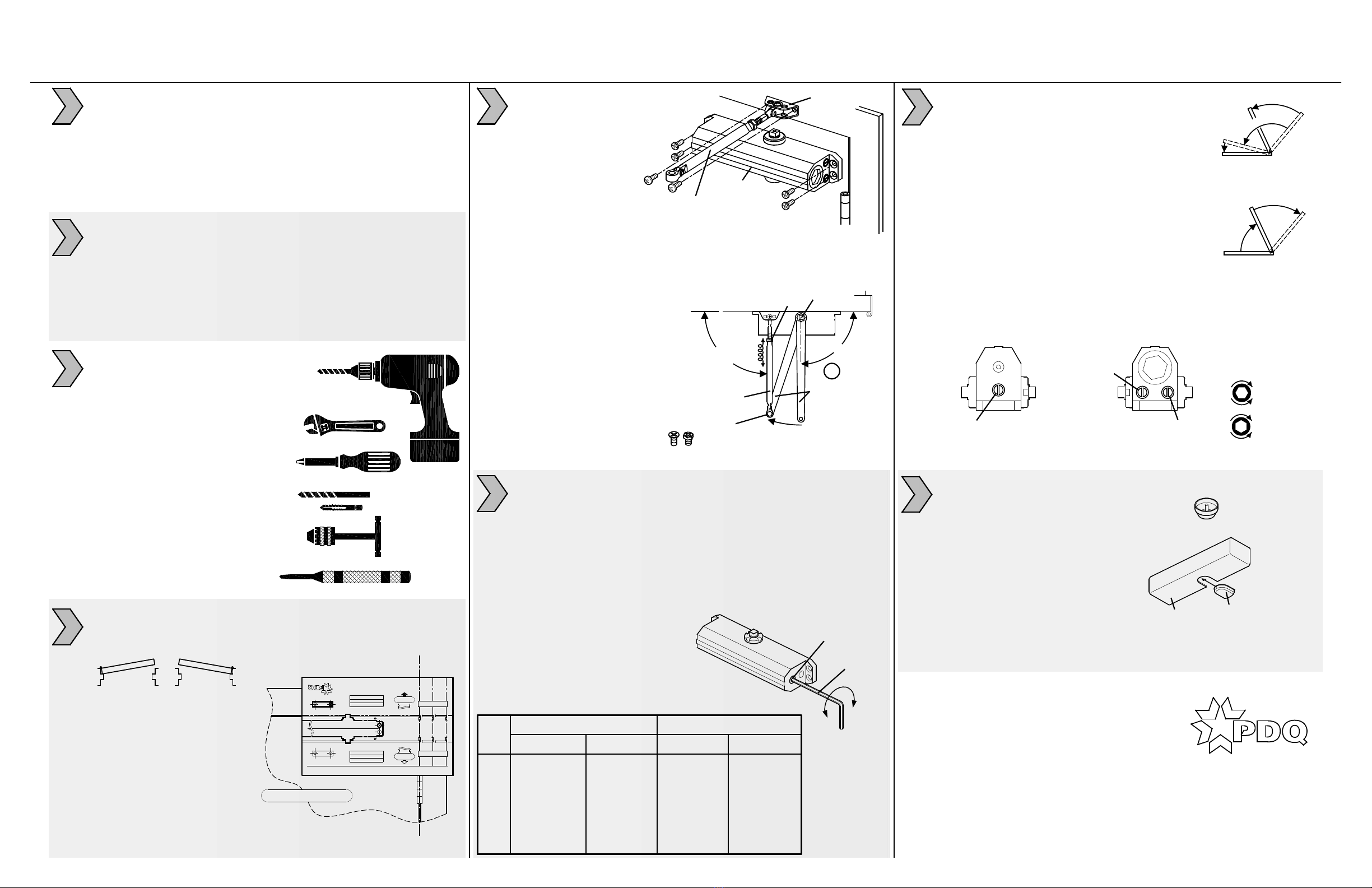
TOOLS REQUIRED:
1. Power drill
2. 14mm box/combo wrench
3. Phillips screw driver
4. #7 or 13/64" drill bit and
1/4-20 tap (machine screws)
5. Tap handle
6. 5/32" drill bit (wood screws)
7. 3/8" drill bit (sex nuts)
8. Center punch
1. See reverse side of this sheet to machine door & frame.
2. Dimensions based on 4-1/2" x 4-1/2" full mortise butt hinges
with 5/8" stop and 1/8" door gap.
3. Confirm door & frame are properly reinforced.
4. Sex nuts required for un-reinforced or composite fire doors.
5. Do not install closer on the exterior (weather) side of building.
1
2
3
4
INSTALL CLOSER AND ARM:
1. Attach closer body to door.
Sweep and latch valves point
toward hinge.
2. Attach foot assembly
to frame.
5
4. Secure main arm to closer spindle,
90° to door/frame.
5. Rotate main arm towards adjustment arm.
6. Shorten (S) or lengthen (L) adjustment arm
until it is 90° to door/frame when
connected with main arm.
7. Secure adjustment arm to
main arm with arm screw
or bolt.
8. Tighten lock-nut against
adjustment arm.
SLOWER
FASTER
INCREASE
DECREASE
1. Use hex key provided.
2. Adjust SWEEP (closing max.°- 10°).
3. Adjust LATCH (closing 10°- 0°).
4. Adjust BACKCHECK resistance (opening 70°- max.°).
DO NOT COMPLETELY CLOSE VALVE
CONTROL ADJUSTMENTS:
CRITICAL: For closer longevity, BACKCHECK
must be adjusted to significantly slow opening
of door before arm bottoms on stop.
Closing time of 3-7 seconds is typical.
More time may be needed for ADA/BF access.
Clockwise (CW) = SLOWER.
Counter-clockwise (CCW) = FASTER.
DO NOT REMOVE VALVES
CLOSING CYCLE
Y
A
L
E
D
E
E
W
S
P
H
C
T
A
L
MAX.°
K
C
A
B
C
E
H
C
K
N
E
P
O
I
N
G
OPENING CYCLE
MAX.°
7
8
PDQ Manufacturing
2230 Embassy Dr.
Lancaster, PA 17603
833-273-7832
833-2 PDQTECH
www.pdqlocks.com
DOOR WIDTH APPROX. 360° TURNS
SIZE INTERIOR EXTERIOR 3100 3101
BF BF ON 36" -- -- -16 (CCW)
1 32" [812.8] 28" [711.2] -- -11 (CCW)
2 36" [914.4] 32" [812.8] -- -6 (CCW)
3 42" [1006.8] 36" [914.4] 0 (PRESET) 0 (PRESET)
4 48" [1219.2] 42" [1006.8] +5 (CW) +5 (CW)
5 54" [1317.6] 48" [1219.2] +9 (CW) --
6 58" [1473.2] 54" [1317.6] +12 (CW) --
MAIN ARM
PRELOAD
TO 90°
90°
6
NUT
ARM SCREW
OR BOLT
SPINDLE/
PINION
ADJUSTMENT
ARM
(S)
(L)
DUST
CAP
INSTALL DUST CAP:
1. Press dust cap over bottom
closer pinion.
INSTALL COVER (Optional):
1. Orient cover so
cutouts align with
closer pinion.
2. Slide pinion cover
into bottom cutout.
3. Slip cover over closer
until flush with door face.
4. Secure with screw provided.
COVER PINION
COVER
!