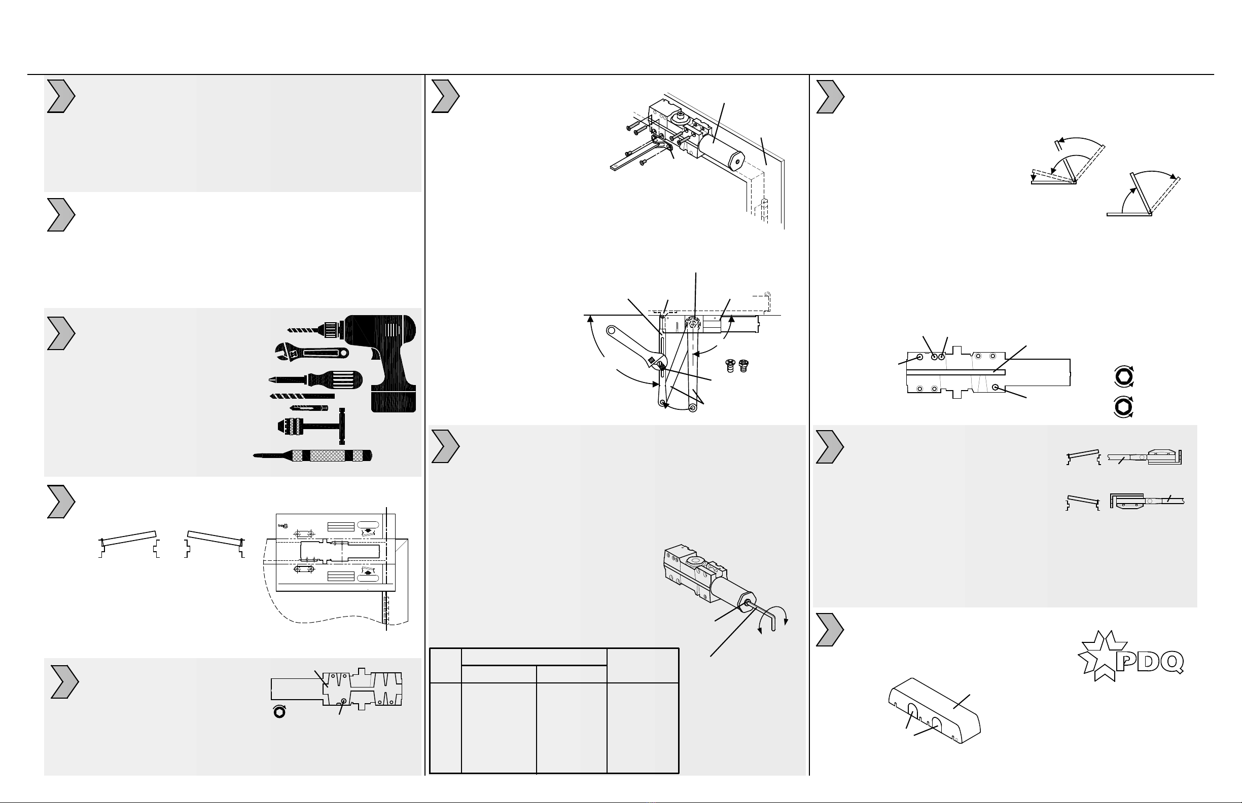
FOOT
ARM SCREW
OR BOLT
MAIN ARM
SPINDLE
ADJUSTMENT
ARM
PRELOAD
TO 90°
FOOT
CLOSER
BODY
CLOSER
BODY
FRAME/STOP
FACE
90°
DOOR
LH RH
CLOSED
BACKCHECK
POSITIONING
PREPARE DOOR AND FRAME:
1. Maximum opening = 120°
2. Determine door hand.
3. Align & attach full size template
(see reverse side).
4. Mark door & frame with center
punch.
5. Remove template before
machining door & frame.
ADVANCE BACKCHECK:
1. For high abuse applications.
2. Backcheck starts 15° to 20°
earlier (50°/55° start).
3. Completely close backcheck
positioning valve to engage advance backcheck.
Leave valve "as is" for normal BC (70° start).
4. If this function is desired, close valve before installing closer.
BACK OF CLOSER
DOOR WIDTH
SIZE INTERIOR EXTERIOR 360° TURNS
BF 5 LBF ON 36" -- -15 (CCW)
1 32" [812.8] 28" [711.2] -12 (CCW)
2 36" [914.4] 32" [812.8] -7 (CCW)
3 42" [1066.8] 36" [914.4] 0 (PRESET)
4 48" [1219.2] 42" [1066.8] +4 (CW)
5 54" [1371.6] 48" [1219.2] +6 (CW)
6 58" [1473.2] 54" [1371.6] +9 (CW)
SPRING POWER
ADJUSTING NUT
HEX
KEY
SWEEP SPEED
DELAYED
ACTION
BACKCHECK
LATCH SPEED
FRONT OF CLOSER
COVER
PERFORATED
TABS
INSTALL COVER:
1. Remove correct tab so cover
slides over spindle.
2. Install cover over closer.
3. Secure with screws provided.
CW
CCW
(-) (+)
LH
RH
NUT DOWN
NUT UP
ARM
ARM
OPTIONAL HOLD OPEN ARM:
Important: DO NOT use arm as limiting
stop, separate dead stop is required.
Friction HO arm is not recommended
for doors frequently operated in/out
of hold open
1. Install hold-open foot/nut.
Left Hand (LH) door = Nut points up.
Right Hand (RH) door = Nut points down.
2. Loosen HO nut.
3. Open door several degrees before HO position.
4. Tighten nut.
7101 DOOR CLOSER INSTRUCTION SHEET
TOP JAMB INSTALLATION - PUSH SIDE - NON-HOLD OPEN AND HOLD OPEN APPLICATIONS - 120° MAX
REV. 3 09-06-19
ADJUST SPRING POWER:
1. Use 4 mm hex key provided to adjust to size on chart.
Clockwise (CW) turns increase spring power (+).
Counter-clockwise (CCW) turns decrease spring power (-).
7100 Series closers can be adjusted to meet
ADA Barrier Free (BF) applications. Compliance with ADA/BF
requirements may result with door not fully closing and latching.
Check with local AHJ. Closer size may vary due to site conditions.
7
1. Confirm this sheet is correct for your product and application.
2. Read the complete instruction sheet before starting installation.
3. Incorrectly installed or adjusted door closers can cause
personal injury or property damage.
4. To ensure safe operation, closers should be examined
and serviced regularly.
TOOLS REQUIRED:
1. Power drill
2. 10mm box/combo wrench
3. Phillips screw driver
4. #7 or 13/64" drill bit and
1/4-20 tap (machine screws)
5. Tap handle
6. 5/32" drill bit (wood screws)
7. 3/8" drill bit (sex nuts)
8. Center punch
1. See reverse side of this sheet to machine door & frame.
2. Dimensions based on 4-1/2" x 4-1/2" full mortise butt hinges
with 5/8" stop and 1/8" door gap.
3. Confirm door & frame are properly reinforced.
4. Sex nuts required for un-reinforced or composite fire doors.
5. Do not install closer on the exterior (weather) side of building.
1
2
3
4
INSTALL CLOSER AND ARM:
1. Attach closer body to frame.
Tube points toward hinges.
2. Attach foot to door.
6
3. Secure main arm to closer spindle 90° to door/frame.
4. Connect adjustment arm with foot assembly:
Rotate main arm until adjustment arm is 90° to door & frame.
Tighten arm screw or bolt .
SLOWER
FASTER
INCREASE
DECREASE
1. Use hex key provided.
2. Adjust SWEEP (closing max.°- 10°).
3. Adjust LATCH (closing 10°- 0°).
4. Adjust BACKCHECK resistance (opening 70°- max.°).
DO NOT COMPLETELY CLOSE VALVE
5. Adjust (optional) DELAYED ACTION (closing max.°- 70°);
Provides additional hesitation for access (ADA/BF) through door.
CONTROL ADJUSTMENTS:
Closing time of 3-7 seconds is typical.
More time may be needed for ADA/BF access.
Clockwise (CW) = SLOWER.
Counter-clockwise (CCW) = FASTER.
DO NOT REMOVE VALVES
CLOSING CYCLE
Y
A
L
E
D
E
E
W
S
P
H
C
T
A
L
MAX.°
K
C
A
B
C
E
H
C
K
N
E
P
O
I
N
G
OPENING CYCLE
MAX.°
8
9
10
PDQ Manufacturing
2230 Embassy Dr.
Lancaster, PA 17603
833-273-7832
833-2 PDQTECH
www.pdqlocks.com
5
PDQ Manufacturing
2754 Creek Hill Rd.
Leola, PA 17540
800-441-9692
Fax: 717-656-6892
www.pdqlocks.com
PAGE 1 OF 2
NON-HOLD OPEN AND HOLD OPEN APPLICATIONS
7101 DOOR CLOSER MODELS INSTRUCTION SHEET
TOP JAMB INSTALLATION - PUSH SIDE (FLUSH HEADER OR SINGLE RABBET FRAME) TEMPLATE: 719352,
REV. 0 10-24-16
CLOSER BODY
(LEFT HAND DOOR)
CLOSER BODY
(RIGHT HAND DOOR)
FOOT
(LH)
FOOT
(RH)
HINGE CENTERLINE
ALIGN WITH BOTTOM OF STOP
ALIGN WITH BOTTOM OF STOP
THIS SIDE UP
FOR RH DOOR
THIS SIDE UP
FOR LH DOOR
ALIGN WITH


