manuals.online logo
Brands
  1. Home
  2. •
  3. Brands
  4. •
  5. PDQ
  6. •
  7. Door Opening System
  8. •
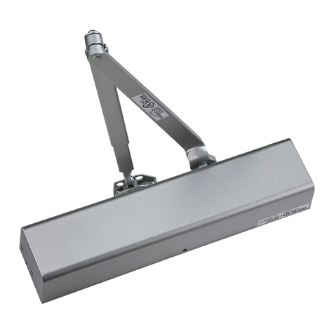
  9. PDQ 5100 User manual

PDQ 5100 User manual

5100 DOOR CLOSER MODELS
TOP JAMB INSTALLATION - PUSH SIDE - PIVOT STOP (PS) ARM APPLICATIONS
INSTRUCTION: 519356
REV.0 10-01-19
MACHINE SCREWS:
USE #7 OR 13/64" [5.1] DRILL AND 1/4-20 TAP
WOOD DOOR/FRAME SCREWS:
USE 5/32" [4] DRILL
SEX NUTS:
USE 3/8" [9.5] DRILL (CLOSER TO DOOR) PDQ Manufacturing
2230 Embassy Dr.
Lancaster, PA 17603
833-273-7832
833-2 PDQTECH
www.pdqlocks.com
1 3/4" [44.5]
1 11/16" [42.9]
B
5/8" [15.9]
3/4" [19.1]
11 1/8" [282.6]
A
BOTTOM OF FRAME FACE
Opening Dim. A Dim. B
85° 10-9/16" [268.3] 16-1/16" [408]
90° 9-15/16" [252.4] 15-7/16" [392.1]
95° 9-3/8" [238.1] 14-7/8" [377.8]
100° 8-7/8" [225.4] 14-3/8" [365.1]
105° 8-7/16" [214.3] 13-15/16" [354]
110° 8-1/16" [204.8] 13-9/16" [344.5]
C
L
HINGE
OR
PIVOT
NOTES:
1. DO NOT SCALE DRAWING. LEFT HAND DOOR SHOWN.
2. DIMENSIONS ARE GIVEN IN INCHES [MM].
3. FOR DOORS WITH REVEAL OF 4 INCHES. CONSULT FACTORY FOR OTHER REVEAL DEPTHS.
4. MINIMUM CEILING CLEARANCE FROM BOTTOM OF FRAME FACE FOR CLOSER : 2-13/16".
5. SEX NUTS REQUIRED FOR UNREINFORCED OR COMPOSITE FIRE DOORS.
6. DOOR AND FRAME MUST BE REINFORCED PER ANSI/SDI A250.8 REQUIREMENTS - MINIMUM THICKNESS
RECOMMENDED FOR REINFORCEMENTS IN HOLLOW-METAL DOORS AND FRAMES: 0.067" UNLESS OTHERWISE NOTED.
7. HOLLOW-METAL DOORS REQUIRE CHANNEL OR BOX-TYPE REINFORCEMENT WHEN SEX NUT MOUNT IS SPECIFIED.
ADJUST SPRING POWER:
1. Use 4 mm hex key provided to adjust to size on chart.
Clockwise (CW) turns increase spring power (+).
Counter-clockwise (CCW) turns decrease spring power (-).
5100 Series closers can be adjusted to meet
ADA Barrier Free (BF) applications. Compliance with ADA/BF
requirements may result with door not fully closing and latching.
Check with local AHJ. Closer size may vary due to site conditions.
LH RH
1. Confirm this sheet is correct for your product and application.
2. Read the complete instruction sheet before starting installation.
3. Incorrectly installed or adjusted door closers can cause
personal injury or property damage.
4. To ensure safe operation, door closers should be examined and
serviced regularly.
INSTALL CLOSER AND ARM:
1. Attach closer body to frame
face. Spring adjustment nut
faces away from hinges.
2. Attach foot to door.
SLOWER
FASTER
INCREASE
DECREASE
CLOSING CYCLE
Y
A
L
E
D
E
E
W
S
P
H
C
T
A
L
MAX.°
K
C
A
B
C
E
H
C
K
N
E
P
O
I
N
G
OPENING CYCLE
MAX.°
PREPARE DOOR AND FRAME:
1. Determine proper opening angle.
2. Determine door hand (LH or RH).
3. Using template (see reverse
side), mark holes on door & frame.
3. Secure main arm to closer spindle 90° to door/frame.
4. Connect adjustment arm with foot assembly:
Rotate main arm until adjustment arm is 90° to door & frame.
Tighten arm screw or bolt .
CW
CCW
(-) (+)
SPRING
POWER/SIZE
ADJUSTING NUT
HEX
KEY
TOOLS REQUIRED:
1. Power drill
2. 10mm box/combo wrench
3. Phillips screw driver
4. #7 or 13/64" drill bit and
1/4-20 tap (metal screws)
5. Tap handle
6. 5/32" drill bit (wood screws)
7. 3/8" drill bit (sex nuts)
8. Center punch
NOTES:
1. See reverse side of this sheet to machine door & frame.
2. Dimensions based on 4-1/2" x 4-1/2" full mortise butt hinges
with 5/8" stop and 1/8" door gap.
3. Confirm door & frame are properly reinforced.
4. Sex nuts required for un-reinforced or composite fire doors.
5. Do not install closer on the exterior (weather) side of building.
1
2
3
4
5
6
7
8
PDQ Manufacturing
2230 Embassy Dr.
Lancaster, PA 17603
833-273-7832
833-2 PDQTECH
www.pdqlocks.com
5100 DOOR CLOSER MODELS
TOP JAMB INSTALLATION - PUSH SIDE - PIVOT STOP (PS) ARM APPLICATIONS
INSTRUCTION: 519356
REV.0 10-01-19
SPINDLE
ADJUSTMENT
ARM
FOOT
6
PRELOAD
TO 90°
ARM SCREW
OR BOLT
MAIN ARM
90°
CLOSER
DOOR WIDTH APPROX.
SIZE INTERIOR EXTERIOR 360° TURNS
1 32" [812.8] 28" [711.2] -5 (CCW)
2 36" [914.4] 32" [812.8] -3 (CCW)
3 42" [1066.8] 36" [914.4] 0 (PRESET)
4 48" [1219.2] 42" [1066.8] +3 (CW)
5 54" [1371.6] 48" [1219.2] +6 (CW)
6 58" [1473.2] 54" [1371.6] +9 (CW)
SWEEP SPEED
CONTROL
DELAYED
ACTION
BACKCHECK
LATCH
SPEED
CONTROL
COVER
INSTALL COVER:
1. Align cover with closer spindle.
Slide insert into unused cutout.
2. Slide cover over closer until
flush with door face.
3. Secure with
screw
provided.
CLOSER
BODY
FOOT
CONTROL ADJUSTMENTS:
CRITICAL: For closer longevity, BACKCHECK
must be adjusted to significantly slow opening
of door before arm bottoms on stop.
Closing time of 3-7 seconds is typical.
More time may be needed for ADA/BF access.
Clockwise (CW) = SLOWER.
Counter-clockwise (CCW) = FASTER.
DO NOT REMOVE VALVES
1. Use hex key provided.
2. Adjust SWEEP (closing max.°- 10°).
3. Adjust LATCH (closing 10°- 0°).
4. Adjust BACKCHECK resistance (opening 70°- max.°).
DO NOT COMPLETELY CLOSE VALVE
5. Adjust (optional) DELAYED ACTION (closing max.°- 70°);
Provides additional hesitation for access (ADA/BF) through
door.
!

Other PDQ Door Opening System manuals

PDQ 3100 User manual

PDQ

PDQ 3100 User manual

PDQ 6EWS STS User manual

PDQ

PDQ 6EWS STS User manual

PDQ 5300 User manual

PDQ

PDQ 5300 User manual

PDQ 6300M/MF User manual

PDQ

PDQ 6300M/MF User manual

PDQ 7101 User manual

PDQ

PDQ 7101 User manual

PDQ 5300 User manual

PDQ

PDQ 5300 User manual

PDQ DOOR CLOSER User manual

PDQ

PDQ DOOR CLOSER User manual

PDQ 7101 User manual

PDQ

PDQ 7101 User manual

PDQ 5300 User manual

PDQ

PDQ 5300 User manual

PDQ 3100 User manual

PDQ

PDQ 3100 User manual

PDQ 3100 User manual

PDQ

PDQ 3100 User manual

PDQ 5100 User manual

PDQ

PDQ 5100 User manual

PDQ 3100 User manual

PDQ

PDQ 3100 User manual

PDQ 6300 User manual

PDQ

PDQ 6300 User manual

PDQ 6300 User manual

PDQ

PDQ 6300 User manual

Popular Door Opening System manuals by other brands

GTO/PRO EXIT WAND installation manual

GTO/PRO

GTO/PRO EXIT WAND installation manual

Assa Abloy SARGENT Powerglide 281 Series installation instructions

Assa Abloy

Assa Abloy SARGENT Powerglide 281 Series installation instructions

Tormax iMotion 1301.FIRE Instructions for use

Tormax

Tormax iMotion 1301.FIRE Instructions for use

Prismatibro Prisma Button 800 installation manual

Prismatibro

Prismatibro Prisma Button 800 installation manual

CAME MI1010 quick start guide

CAME

CAME MI1010 quick start guide

Brookfield Industries NB-500 manual

Brookfield Industries

Brookfield Industries NB-500 manual

Eco TS-50 Assembly instruction

Eco

Eco TS-50 Assembly instruction

4Ddoors 4DR1 v4 Installation instructions and owner's manual

4Ddoors

4Ddoors 4DR1 v4 Installation instructions and owner's manual

Assa Abloy Pando Mini Go quick start guide

Assa Abloy

Assa Abloy Pando Mini Go quick start guide

ATIM Ghost vetro 880 Assembly instructions

ATIM

ATIM Ghost vetro 880 Assembly instructions

Dorex 1701 Series installation instructions

Dorex

Dorex 1701 Series installation instructions

Dorma EM 508 Series installation instructions

Dorma

Dorma EM 508 Series installation instructions

Dormakaba UNIVERSAL PT 29 Mounting instructions

Dormakaba

Dormakaba UNIVERSAL PT 29 Mounting instructions

BRINKS BC4007 installation instructions

BRINKS

BRINKS BC4007 installation instructions

Assa Abloy DC 700G-FT BGS installation instructions

Assa Abloy

Assa Abloy DC 700G-FT BGS installation instructions

Assa Abloy SW60 Installation and service manual

Assa Abloy

Assa Abloy SW60 Installation and service manual

SECO-LARM SD-969-A18Q installation manual

SECO-LARM

SECO-LARM SD-969-A18Q installation manual

ECO Schulte ECO SR-EF Assembly instruction

ECO Schulte

ECO Schulte ECO SR-EF Assembly instruction

manuals.online logo
manuals.online logoBrands
  • About & Mission
  • Contact us
  • Privacy Policy
  • Terms and Conditions

Copyright 2025 Manuals.Online. All Rights Reserved.