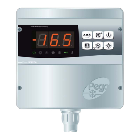
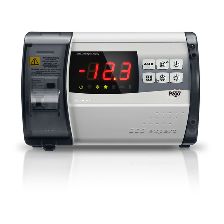
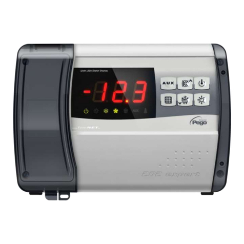
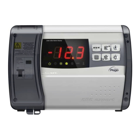
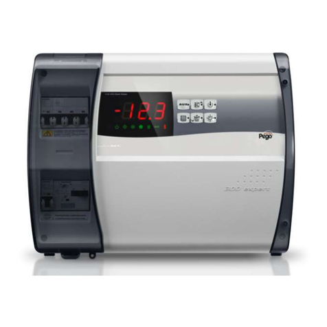
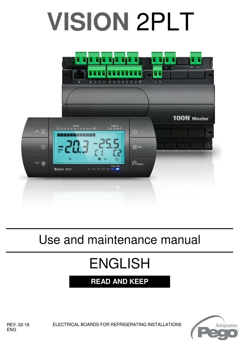
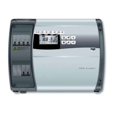
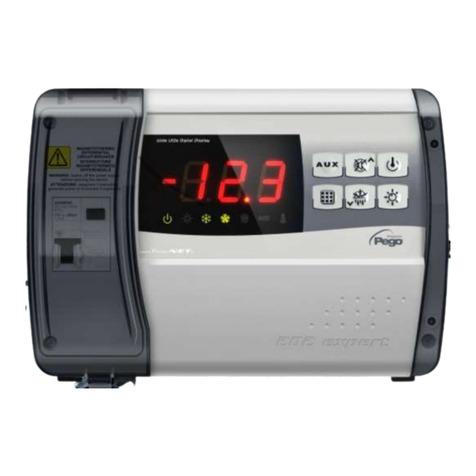
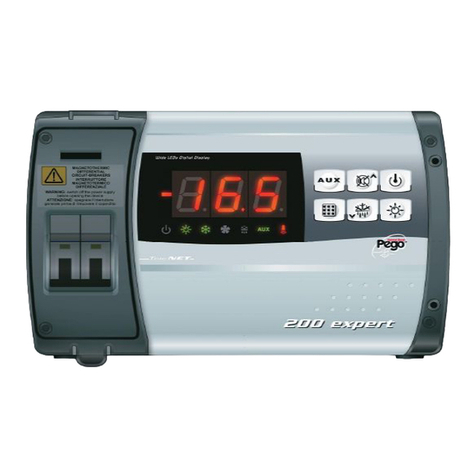
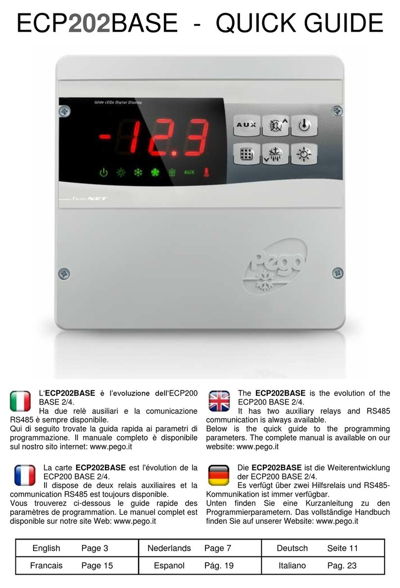
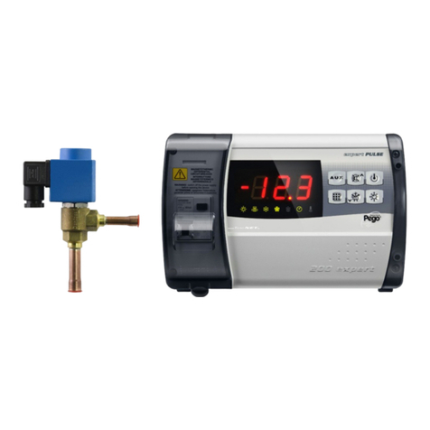
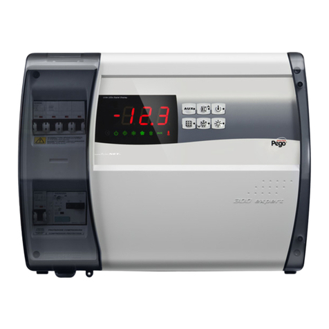
Pego ECP300 EXPERT VD Series User manual

ECP300 EXPERT STEPPER
Page 1
OPERATION AND MAINTENANCE
MANUAL
Rev. 01-18
Software Rel.: 1
Operation and maintenance manual
ELECTRICAL BOARDS FOR REFRIGERATING INSTALLATIONS
READ AND KEEP
REV. 01-20
ITA
ECP300 EXPERT
STEPPER
for EEV STEPPER

ECP300 EXPERT STEPPER
Page 2
OPERATION AND MAINTENANCE MANUAL
Rev. 01-20
Thank you for choosing a PEGO electrical panel.
This manual provides detailed information on the installation, use and maintenance of the
ECP300 EXPERT STEPPER series of electrical panels. Our products are designed and
manufactured in compliance with current safety standards, in the specific field of use of
refrigeration and air conditioning systems. Different use is allowed provided that the
operating conditions for which the panel was designed and manufactured are respected.
Before using the panel, it is advisable to read this manual in full, paying particular attention
to the parts highlighted with the symbols described below:
This symbol is placed to indicate notes concerning installation, use and
maintenance operations.
This symbol is placed to highlight notes of particular importance.
This symbol is placed to indicate the prohibition to perform the
indicated operation.
Disposal information:
The electrical panel consists of metal parts and plastic parts. With reference to Directive
2012/19/EU of the European Parliament and of the Council of 4 July 2012 and the relevant
national legislation on the subject, we inform you that:
A. There is an obligation not to dispose of WEEE as municipal waste and to carry out
separate collection of such waste.
B. Public or private collection systems provided for by local laws should be used for
disposal. It is also possible to return the equipment to the distributor at the end of its
life if a new one is purchased.
C. This equipment may contain hazardous substances: improper use or improper
disposal could have adverse effects on human health and the environment.
D. The symbol (crossed-out wheeled bin) on the product and instructions
indicates that the equipment was placed on the market after August 13, 2005 and
must be collected separately.
E. In the event of improper disposal of electrical and electronic waste, penalties are
established by current local regulations on disposal.

ECP300 EXPERT
Page 3
OPERATION AND MAINTENANCE MANUAL
Rev. 01-20
INTRODUCTION
Page 4 1.1 General information
TECHNICAL SPECIFICATIONS
Page 5 2.1 Product identification codes
Page 5 2.2 Technical characteristics per product series
Page 6 2.3 Overall dimensions
Page 6 2.4 Identification data
Page 6 2.5 Transport and storage
Page 7 2.6 Warranty conditions
INSTALLATION
Page 8 3.1 Standard equipment for assembly and use
Page 8 3.2 Mechanical assembly of the panel
Page 12 3.3 Electrical connections
Page 13 3.4 Connection of the front panel
Page 14 3.5 Pre-use checks
Page 15 3.7 Closing the electrical panel
FUNCTIONALITY
Page 16 4.1 Functions managed by the ECP300 EXPERT STEPPER electrical panel
DATA PROGRAMMING
Page 17 5.1 Control panel
Page 17 5.2 Front keyboard
Page 18 5.3 LED Display
Page 19 5.4 Key combinations
Page 19 5.5 Switching on the ECP300 EXPERT STEPPER panel
Page 20 5.6 General information
Page 20 5.7 Symbols
Page 20 5.8 Setting and set-point display
Page 20 5.9 First level programming (user level)
Page 21 5.10 List of first level variables
Page 22 5.11 Second level programming (installer level)
Page 22 5.12 List of second level variables
Page 26 5.13 Third level programming (EEV parameters)
Page 26 5.14 List of third level variables
Page 28 5.15 Loading default settings based on the EEV variable
Page 29 5.16 Fourth level programming (stepper valve)
Page 29 5.17 List of fourth level variables (stepper valve)
Page 31 5.18 Refrigeration fluid temperature table
Page 31 5.19 Quick menu for variable display
Page 31 5.20 List of variables in the quick display menu
Page 32 5.21 Thermostat operating mode
Page 32 5.22 Password function
Page 32 5.23 Emergency operation in case of error E0
Page 32 5.24 Manual defrost activation
Page 33 5.25 Manually forced defrost stop in progress
Page 33 5.26 Defrosting with thermostat resistors
Page 33 5.27 Hot gas defrosting
Page 33 5.28 Ambient temperature display after defrost
Page 33 5.29 Pump-Down function
Page 33 5.30 Initial start-up procedure
OPTIONS
Page 34 6.1 TeleNET monitoring / supervision system
Page 34 6.2 Network configuration with Modbus-RTU protocol
DIAGNOSTICS
Page 35 7.1 Diagnostics by means of alarm codes
Page 37 7.2 Troubleshooting
MAINTENANCE
Page 38 8.1 General safety rules
Page 39 8.2 Maintenance
Page 39 8.3 Spare parts/Accessories
ATTACHMENTS / APPENDICES
Page 40 A.1 EU Declaration of Conformity
Page 41 A.2 Connection diagram of the electronic board
Page 43 A.3 Connection diagram to the TeleNET network
CHAP. 1
Table of contents
CHAP. 3
CHAP. 4
CHAP. 5
CHAP. 2
CHAP. 6
CHAP. 7
CHAP. 8
TABLE OF CONTENTS
Page 44 A.4 Positioning and description of probes
Page 45 A.5 Valve connection

ECP300 EXPERT STEPPER
Page 4
OPERATION AND MAINTENANCE MANUAL
Rev. 01-20
GENERAL INFORMATION
DESCRIPTION:
Line of panels with power and electronic control dedicated to the management of a single
three-phase evaporator unit where utilities are serviced by a refrigeration centre or a
remote motorised condenser unit.
ECP300 EXPERT STEPPER
Electrical panel, with power and control of the stepper electronic expansion valve (stepper
motor), dedicated to the management of the three-phase evaporator unit.
APPLICATIONS:
−Management of evaporator units with electrical defrosting up to 12 kW.
−Bipolar motorised expansion valve management.
−Remote control for compressor consent to be combined with power panel.
1.1
CHAPTER 1: INTRODUCTION
CHAP. 1 - Introduction

ECP300 EXPERT STEPPER
Page 5
OPERATION AND MAINTENANCE MANUAL
Rev. 01-20
PRODUCT IDENTIFICATION CODES
11030ESUVD02 Control and management of motorised electronic
expansion valve, consent for motorised
condensing unit, defrosting resistors (up to 12kW),
evaporator fans, solenoid valve, cold room light,
door resistance and presence of all the electrical
protections required by regulations. Connectable
to any type of bipolar stepper valve on the market.
TECHNICAL SPECIFICATIONS PER PRODUCT SERIES
TECHNICAL SPECIFICATIONS
11030ESUVD02
Case size
400x300x135 mm
Weight
10 Kg
Protection level
IP65
Power supply (3F + N + T)
400Vac ±10% 50-60Hz
Command type
Three-phase
Working temperature
- 5 ÷ + 40 °C
Storage temperature
-25 ÷ +55 °C
Relative ambient humidity
<90% RH non-condensing
Probe reading range
-45 ÷ +99 °C
General switch/general protection
Interruption capacity
Four-pole magnetic-thermal switch 25A "C”
Icn=6kA / Ics=8kA / Icu=15kA
Dedicated protection for COLD ROOM LIGHT
Differential magnetic-thermal switch Id=30mA
Control
PEGO
Defrosting
Electrical
Component status indication
LED + display
Alarm signals
LED + Buzzer
Ambient probe
NTC 10K 1%
Evaporator probe
NTC 10K 1%
Suction probe
NTC 10K 1%
Evaporation pressure probe
4-20mA
Door switch
Present
Man in cold room alarm
Available
Evaporator fans
2 x 1500W (1ph / 3ph)
Defrosting
12000W (3x4000) (AC1) balanced resistive load
Cold room light
1200W (AC1) resistive load
Stepper Valve Outlet
Bipolar
Consent for motorised condensing unit
Present
Configurable auxiliary relays (alarm / Aux)
100W
Door resistor
Present
Supervision
TeleNET or Modbus
Connection diagram
See attached wiring diagram
CHAPTER 2: TECHNICAL SPECIFICATIONS
2.1
CHAP. 2 - Technical specifications
2.2

ECP300 EXPERT STEPPER
Page 6
OPERATION AND MAINTENANCE MANUAL
Rev. 01-20
OVERALL DIMENSIONS
IDENTIFICATION DATA
The apparatus described in this manual is provided on its side with a plate showing its
identification data:
• Manufacturer's Name
• Electrical panel code
• Serial number (S.N.)
• Supply voltage
• Auxiliary circuit voltage
• IP protection level
TRANSPORT AND STORAGE
Each electrical panel is supplied packed to be shipped without being damaged under
normal conditions of transport. In the case of subsequent transport, it must be verified that:
❑There are no objects or free parts inside the panel.
❑The panel door is correctly closed and locked.
❑If the original packaging is not used, adequately protect the product to
allow it to be transported without damage.
The room intended for storage must have an adequate temperature and must be free from
moisture; furthermore, the electrical panel must not come into contact with aggressive
contaminants, which could impair its functionality and electrical safety.
2.3
2.4
CHAP. 2 - Technical specifications
2.5

ECP300 EXPERT STEPPER
Page 7
OPERATION AND MAINTENANCE MANUAL
Rev. 01-20
WARRANTY CONDITIONS
The ECP300 EXPERT STEPPER series of electrical panels are covered by warranty against
all manufacturing defects for 24 months from the date indicated on the product identification
code.
In the event of a defect, the equipment must be shipped with appropriate packaging to our
Authorized Facility or Service Centre, upon previous request of the return authorization
number.
The Customer is entitled to the repair of the defective equipment including labour and spare
parts. Transport costs and risks are borne entirely by the Customer.
Any intervention under warranty does not extend or renew the expiry of the same.
The warranty is voided in case of:
•Damage due to tampering, carelessness, inexperience or improper installation of the
equipment.
•Installation, use or maintenance not in accordance with the requirements and instructions
provided with the equipment.
•Repair operations carried out by unauthorised personnel.
•Damage due to natural phenomena such as lightning, natural disasters, etc.
In all these cases the costs for the repair will be borne by the customer.
Warranty service may be refused when the equipment is modified or transformed.
Under no circumstances will Pego S.r.l. be liable for any loss of data and information, costs of
substitute goods or services, damage to property, persons or animals, loss of sales or income,
interruptions of activities, any direct, indirect, incidental, property, coverage, punitive, special
or consequential damages caused in any way, whether contractual, extra-contractual or due to
negligence or other liability arising from the use of the product or its installation.
Malfunction caused by tampering, impact, improper installation automatically voids the
warranty. It is mandatory to comply with all the instructions in the following manual and the
operating conditions of the equipment.
Pego S.r.l. declines all responsibility for the possible inaccuracies contained in this manual, if
due to printing or transcription errors.
Pego S.r.l. reserves the right to make any changes to its products that it deems necessary or
useful, without affecting their essential characteristics.
Each new release of Pego product manuals replaces all previous releases.
For anything not expressly indicated, the legal provisions in force and in particular art. 1512 of
the Italian Civil Code apply to the warranty.
For any dispute, the jurisdiction of the Court of Rovigo shall be deemed elected and
recognised by the parties.
2.6
CHAP. 2 - Technical specifications

ECP300 EXPERT STEPPER
Page 8
OPERATION AND MAINTENANCE MANUAL
Rev. 01-20
STANDARD EQUIPMENT FOR ASSEMBLY AND USE
The ECP300 EXPERT STEPPER electrical panel, for assembly and use, is equipped with:
• 4 Seals, to be interposed between the fixing screw and the bottom of the case.
• 1 Operation and maintenance manual.
• 1 Wiring diagram.
• 1 Drilling template.
• 2 NTC 10K Probes 1% .
MECHANICAL ASSEMBLY OF THE PANEL
❑Each panel is designed for wall mounting; choose an appropriate fastening
system depending on the weight of the panel and the type of wall.
❑Install the equipment in places that respect its protection level.
❑Keep the IP protection level of the equipment intact by fitting cable glands
and/or pipe glands with adequate characteristics.
❑Install the equipment at a height that allows easy use and inside access by
the operator. The operator must not be in a dangerous situation when
operating on the panel. In any case, the height must be between 0.6 and 1.7
metres from the service floor.
❑Install the equipment in an area away from heat sources and possibly
protected from atmospheric agents.
Below are the steps to perform a correct mechanical installation of the panel.
Fig. 1: Lift the transparent protective door
of the general thermal magnetic
switch.
CHAPTER 3: INSTALLATION
3.2
CHAP. 3 - Installation
3.1

ECP300 EXPERT STEPPER
Page 9
OPERATION AND MAINTENANCE MANUAL
Rev. 01-20
Fig. 2: Remove the cover of the screws on the
right side.
Fig. 3: Unscrew the 4 fixing screws of the front
panel.
Fig. 4: Close the transparent protective door of
the general thermal magnetic switch.
CHAP. 3 - Installation

ECP300 EXPERT STEPPER
Page 10
OPERATION AND MAINTENANCE MANUAL
Rev. 01-20
Fig. 5: Open the front of the panel by lifting it
and sliding the two hinges to the end
of their travel.
Fig. 6: Bend the hinges and rotate the front
piece 180° downwards to access the
inside of the panel and disconnect the
connector of the electronic board.
Fig. 7: Apply pressure to the sides of each
individual hinge to remove it from its
seat and completely remove the front
piece.
Fig. 8: Using a screwdriver, press on the four
pre-marked holes in the bottom to
make the holes for fixing the electrical
panel.
CHAP. 3 - Installation

ECP300 EXPERT STEPPER
Page 11
OPERATION AND MAINTENANCE MANUAL
Rev. 01-20
Fig. 9: Using the supplied drilling template
sheet, make the four fixing holes on
the wall.
Fig.10: Using the holes made previously,
fix the bottom of the case with four
screws of adequate length in
relation to the thickness of the wall
on which to fix the panel. Place a
rubber washer (supplied) between
each fixing screw and the bottom
of the case.
Fig.11: Now make the electrical
connections as indicated in the
following chapter.
CHAP. 3 - Installation

ECP300 EXPERT STEPPER
Page 12
OPERATION AND MAINTENANCE MANUAL
Rev. 01-20
ELECTRICAL CONNECTIONS
❑For electrical connections refer to the specific wiring diagram and the
technical characteristics of the panel model to be installed.
❑The power supply to the panel must be carried out exclusively with a
dedicated line, upstream of which a device suitable for protection from
indirect contacts (differential switch) must be installed.
❑Avoid housing power cables together with signal cables (probes and digital
inputs) in the same ducts (or tubes).
❑Avoid using multi-pole cables in which conductors connected to inductive
and power loads and signal conductors are present, such as probes and
digital inputs.
❑Reduce the lengths of the connection cables as much as possible, avoiding
that the wiring takes on the shape of a spiral capable of possible inductive
effects on the electronics.
❑If it is necessary to move the probes farther, it is necessary to use
conductors of appropriate cross-section and in any case not less than 1
mm2.
❑Cables with a section suitable for the current passing through them must be
used for connections to the panel. Similarly, the degree of insulation must be
compatible with the voltages applied. Cables with flame-retardant insulation
and low toxic smoke emissions are preferable if affected by fire.
❑It is mandatory to connect the terminal marked PE to the ground system of
the power supply network. If necessary, check the efficiency of the earthing
system.
❑Other conductors must not be connected to the PE terminal except for the
external protection conductor.
3.3
CHAP. 3 - Installation

ECP300 EXPERT STEPPER
Page 13
OPERATION AND MAINTENANCE MANUAL
Rev. 01-20
FRONT PANEL CONNECTION
Now reattach the front piece and reconnect the electronic board connector as shown
below.
Fig.12: Reattach the front piece to the bottom
of the case by reinserting the two
hinges in the appropriate seats.
Fig.13: Bend the hinges and rotate the front
180° downwards to access the inside
of the panel and reconnect the
connector of the electronic board.
Fig.14: If the panel is connected to a
TeleNET/Modbus network and/or the
Aux/Alarm relay is used, make the
necessary connections directly on the
terminals of the electronic board.
As a cable path for these connections,
it is recommended to place the existing
connection cord between the electronic
board and the bottom of the panel.
For further clarification on the
connection terminals refer to chapter
6.1.
3.4
CHAP. 3 - Installation

ECP300 EXPERT STEPPER
Page 14
OPERATION AND MAINTENANCE MANUAL
Rev. 01-20
PRE-USE CHECKS
❑Once the connections have been made, review the correct execution of the
same using the wiring diagram.
❑Ensure that the screws are tightened correctly on the terminal boards.
❑Check, when possible, the correct operation of the external protection
devices.
❑Perform a correct calibration of the motor saver dedicated to the
compressor motor as indicated in the next chapter (if present).
❑After powering the electrical panel, check the correct current absorption of
the various user loads and, after operating the system for a few hours, it is
recommended to check the correct tightening of the terminal board screws
(including the connection of the power supply line).
Caution: before performing this operation, it is necessary to disconnect the
power supply line upstream and lock the disconnection switch with a
padlock to ensure maximum safety. Check the absence of voltage with a
Tester before any operation.
CHAP. 3 - Installation
3.5

ECP300 EXPERT STEPPER
Page 15
OPERATION AND MAINTENANCE MANUAL
Rev. 01-20
CLOSING THE ELECTRICAL PANEL
Once the electrical connections, checks and necessary calibrations have been completed,
the electrical panel can be closed.
Fig.18: Close the front cover, making sure
that all the cables are inside the
case and that the case gasket is
correctly housed in its seat.
Fig.19: Tighten the front cover with the 4
screws. Replace the screw cover on
the right side.
Fig.20: Connect the supply voltage to the
panel and carefully read/program all
the set parameters.
CHAP. 3 - Installation
3.6

ECP300 EXPERT STEPPER
Page 16
OPERATION AND MAINTENANCE MANUAL
Rev. 01-20
FUNCTIONS MANAGED BY THE ECP300 EXPERT STEPPER ELECTRICAL PANEL
-Compatible with 23 gas types: R404, R134, R22, R407A, R407F, R407H, R410A,
R450A, R507, R513A, R744(CO2), R449A, R290, R32, R448A, R452A, R600, R600A,
R1270, R1234ze, R23, R717(NH3), R454C.
-Easy valve parameter programming with 21 pre-sets for the most popular valves on the
market. Ability to manually define valve parameters.
-Easy parameter programming with 4 pre-sets for the different applications of the
electronic expansion valve.
-Safety solenoid valve management with the system stopped.
-Connectable to the backup battery module to allow the stepper valve to close in the
absence of source voltage.
-Display and adjustment of the cell temperature with decimal point.
-Evaporator temperature display by parameter.
-Configurable digital inputs.
-Activation/deactivation of system control.
-System alarm signal (probe error, minimum and maximum temperature alarm,
compressor protection, overheating anomalies).
-LED signals of the system status and large displays.
-Easy to use keyboard.
-Evaporator fan management.
-Air recirculation management in anti-stratification function.
-Emergency operation in case of ambient probe breakage.
-Automatic and manual defrosting management (static, resistor, thermostat resistor).
-Energy saving: day/night mode and intelligent defrosting.
-Consent for motorised condensing unit.
-Cold room light activation with button on the panel or via Door switch.
-Integrated differential magnetic-thermal switch for the protection and disconnection of
the refrigeration unit.
-Self-extinguishing ABS case, with transparent access door to the magnetic-thermal
differential protection, with IP65 protection level that allows it to be used as an external
cell panel.
-Two alarm/auxiliary relays with activation configurable by parameter.
-RS485 for connection to the TeleNET supervision network or to a network with
Modbus-RTU protocol.
-Import / export parameters via USB.
-Software upgradeable via USB.
CHAPTER 4: FUNCTIONALITY
4.1
CHAP. 4 - Functionality

ECP300 EXPERT STEPPER
Page 17
OPERATION AND MAINTENANCE MANUAL
Rev. 01-20
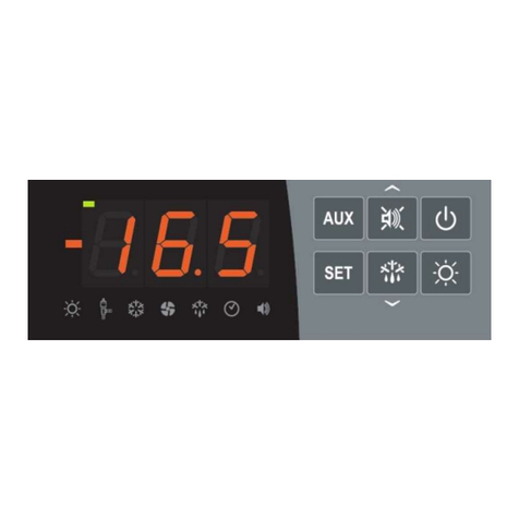
CONTROL PANEL
FRONT KEYBOARD
AUXILIARY RELAY COMMAND / PARAMETER SAVING to USB
Manually controls the relay if parameter AU1/AU2=2.
If pressed for 3 seconds it accesses the parameter export/import menu via USB.
UP KEY / MUTE BUZZER ALARM
Increases values / Scrolls up parameters.
Mutes the audible alarm if present / Acquires an alarm (if the alarm has returned and the
bell is lighted, pressing this key turns off the bell as the alarm is acquired. If pressed for 3
seconds together with the standby button, it allows access to the valve adjustment menu
(EEV parameters, level 3).
STAND BY
Pressed for more than 1 second toggles the standby state to the normal operating state
and vice-versa. Upon switching, a confirmation BEEP is generated.
In the standby state, the system stops and the display alternates the OFF word with the
temperature (if programmed, the alternate OFF word is not displayed)
AMBIENT TEMPERATURE SETTING
Displays the set-point. Allows you to set the set-point if pressed in combination with the
Down key or the UP key. Resets the audible alarm if present. If pressed for 3 seconds
together with the standby button, allows access to the valve configuration menu
(STEPPER parameters, level 4).
CHAP. 5 - Data programming
CHAPTER 5: DATA PROGRAMMING
5.1
5.2

ECP300 EXPERT STEPPER
Page 18
OPERATION AND MAINTENANCE MANUAL
Rev. 01-20
DOWN / DEFROST
Pressed for more than 3 seconds activates manual defrosting (if the activation conditions
are met).
Pressed for more than 3 seconds during defrosting, it ends the present defrosting.
COLD ROOM LIGHT
LED DISPLAY
AMBIENT TEMPERATURE/PARAMETER VALUES
DOOR SWITCH/COLD ROOM LIGHT ICON
Led OFF = Door switch not active or not used and Cold room light off
Led ON = Cold room light ON
Flashing Led = Active Door switch and Cold room light ON
EEV STEPPER OUTPUT STATUS ICON output status of the EEV Stepper electronic valve
(if enabled)
Led OFF = Motorised valve closed
Led ON = Motorised valve open
COLD CALL ICON
Led OFF = Cold call OFF
Led ON = Cold call ON
Flashing Led = Cold call ON but waiting for waiting time C1
FAN CALL ICON
Led OFF = Fan call OFF
Led ON = Fan call ON
DEFROST CALL ICON
Led OFF = Defrost call OFF
Led ON = Defrost call ON
Flashing LED = Dripping in progress after defrosting (see parameter d7)
REAL TIME CLOCK ICON
Led OFF = Real time clock defrosting disabled
Led ON = Real time clock defrosting enabled
ALARM PRESENCE ICON
Led OFF = No alarm present
Led ON = Alarm activated and then returned
Flashing LED = Alarm present
DECIMAL POINT (flashing in night mode)
AUXILIARY (AUX relay call signal if AU1=+/-2 or +/-3)
5.3
CHAP. 5 - Data programming

ECP300 EXPERT STEPPER
Page 19
OPERATION AND MAINTENANCE MANUAL
Rev. 01-20
KEY COMBINATIONS
+
1ST-LEVEL PROGRAMMING
If pressed simultaneously for more than 3 seconds, they allow
access to the first level programming menu.
LEAVING THE PROGRAMMING
If pressed simultaneously for more than 3 seconds within any
programming menu.
+ +
2ND-LEVEL PROGRAMMING
If pressed simultaneously for more than 3 seconds, they allow
access to the second level programming menu.
The entry in this menu activates the stand-by.
+
3RD-LEVEL PROGRAMMING
(EEV parameters)
If pressed simultaneously for more than 3 seconds, they allow
access to the third level programming menu.
The entry in this menu activates the stand-by.
+
4TH LEVEL PROGRAMMING
(stepper valve parameters)
If pressed simultaneously for more than 3 seconds, they allow
access to the fourth level programming menu. The entry in this
menu activates the stand-by.
+
QUICK MENU FOR VARIABLE DISPLAY
(READ-ONLY)
If pressed simultaneously for more than 3 seconds, they allow
access to the quick variable display menu.
Within this menu the up and down arrows allow the display of
the variable label.
Pressing the Set key toggles the display of the label with its
value.
When the label value is displayed, pressing the up or down
arrow alternates the value display for the label display.
The leaving from this menu takes place automatically after 2
minutes of keyboard inactivity or by pressing up arrow + down
arrow.
SWITCHING ON THE ECP300 EXPERT STEPPER PANEL
After completing all the electrical panel wiring connections, power the panel using the
general switch; the electrical panel will emit immediately a sound for a few seconds and at
the same time, all the LEDs will remain lighted on the display.
CHAP. 5 - Data programming
5.5
5.4

ECP300 EXPERT STEPPER
Page 20
OPERATION AND MAINTENANCE MANUAL
Rev. 01-20
GENERAL INFORMATION
For safety reasons and greater convenience for the operator, the ECP300 EXPERT
STEPPER system provides four programming levels; the first is used only for the
configuration of frequently editable SET-POINT parameters, the second is used for
programming and setting the general parameters relating to the various operating modes
of the board, the third is used for managing the parameters relating to the electronic
expansion valve and the fourth is used for managing the parameters relating to the stepper
valve.
If you are at one programming level, you cannot directly access another level, but you
must first leave the programming.
SYMBOLS
For convenience we will indicate with the symbols:
•()the UP key that performs the functions of value increase and tacit alarm.
•()the DOWN key that performs the functions of decreasing the values and
forcing defrosting.
SETTING AND SET-POINT DISPLAY
1. Press the SET key to display the current SET-POINT value (temperature).
2. Holding down the SET key and pressing one of the () or () keys changes the SET-
POINT value.
3. Release the SET key to return to the cell temperature display; the changes made will
be automatically saved.
FIRST-LEVEL PROGRAMMING (User level)
To access the first level configuration menu you must:
1. Press and hold the () and () keys simultaneously for more than 3 seconds until the
first programming variable appears on the display.
2. Release the () and () keys.
3. Select with the () key or the () key the variable to be modified.
4. After selecting the desired variable you will be able to:
• Display the setting by pressing the SET key.
• Change the setting by holding down the SET key and pressing one of the () or ()
keys.
Once the configuration values have been set, to leave the menu, press and hold the ()
and () keys for a few seconds until the cell temperature value reappears.
Changes made to the variables will be automatically saved when leaving the configuration
menu.
CHAP. 5 - Data programming
5.9
5.8
5.7
5.6
Other manuals for ECP300 EXPERT VD Series
2
This manual suits for next models
1
Table of contents
Other Pego Control Panel manuals

Pego
Pego VISION Series User manual

Pego
Pego ECP 200 Base 2 User manual

Pego
Pego ECP300 EXPERT VD Series User manual

Pego
Pego 202BASE User manual

Pego
Pego PLUS300 Expert VD 4 User manual

Pego
Pego ECP200 Expert d7.5 User manual

Pego
Pego ECP202 EXPERT User manual

Pego
Pego ECP202 EXPERT User manual

Pego
Pego 100N MASTER3 Operating instructions

Pego
Pego ECP202 EXPERT User manual