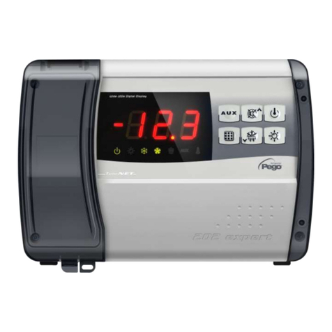
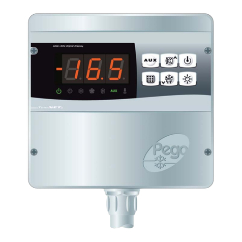
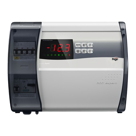
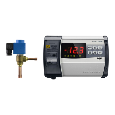
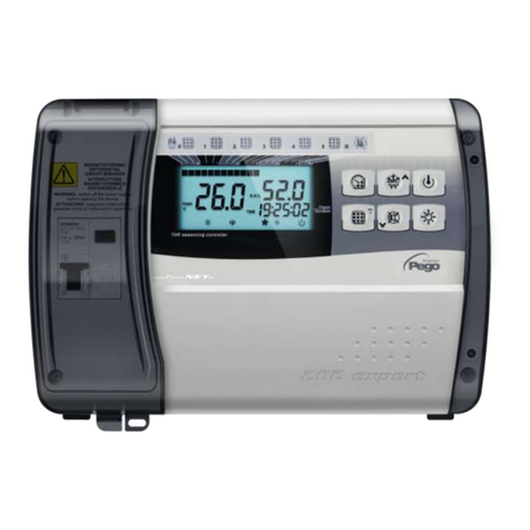
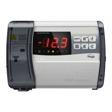
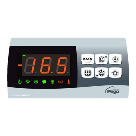
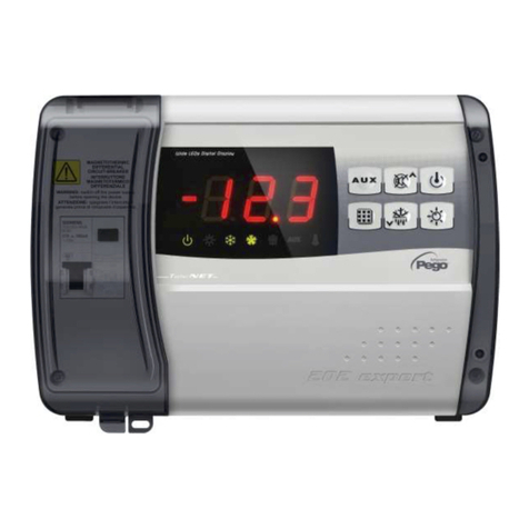
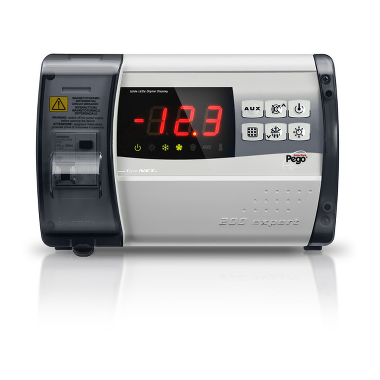
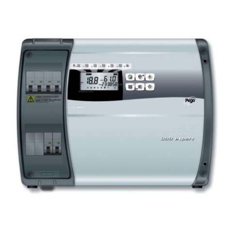
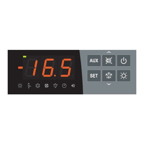
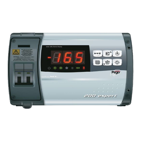
Pego ECP300 EXPERT VD Series User manual

Rel. Software: 26
Use and maintenance manual
ELECTRICAL BOARDS FOR REFRIGERATING INSTALLATIONS
READ AND KEEP
REL. 01-21
ENG
ECP300 EXPERT

ECP300 EXPERT
Page 2
USE AND MAINTENANCE MANUAL
Rel. 01-21
Thanks for choosing this PEGO electrical panel.
This manual gives detailed information on installation, use and maintenance of ECP300
EXPERT series electrical panels and special version. Our products are designed and built
in compliance with current standards, on the specific field of refrigeration and conditioning
systems. A different use is allowed respecting the working conditions for which the panel is
designed and made.
Before using the panel it’s suggested to fully read this manual paying special attention to
the highlighted parts with the simbology descripted below:
This symbol is used to focus on notes concerning installation, use and
maintenance operations
This symbol is used to focus on important notes
This symbol is used to indicate the prohibition to do the shown
operation
Instructions for disposal:
The electric board is made up of metal parts and plastic parts. In reference to European
Union directive 2012/19/EC issued on 4 July 2012 and the related national legislation,
please note that:
A. WEEE cannot be disposed of as municipal waste and such waste must be collected
and disposed of separately.
B. The public or private waste collection systems defined by local legislation must be
used. In addition, the equipment can be returned to the distributor at the end of its
working life when buying new equipment.
C. The equipment may contain hazardous substances: the improper use or incorrect
disposal of such may have negative effects on human health and on the
environment.
D. The symbol (crossed-out wheeled bin) shown on the product and on the user
manual indicates that the equipment has been introduced onto the market after 13
August 2005 and that it must be disposed of separately.
E. In the event of illegal disposal of electrical and electronic waste, the penalties are
specified by local waste disposal legislation.

ECP300 EXPERT
Page 3
USE AND MAINTENANCE MANUAL
Rel. 01-21
INTRODUCTION
Pag. 4 1.1 Generality
TECHNICAL CHARACTERISTICS
Pag. 5 2.1 Product ID codes
Pag. 6 2.2 Product series - Technical characteristics
Pag. 8 2.3 Overall dimensions
Pag. 9 2.4 Identification data
Pag. 10 2.5 Transport and storage
Pag. 11 2.6 Warranty conditions
INSTALLATION
Pag. 12 3.1 Standard equipment for assembly and use
Pag. 12 3.2 Mechanical assembly of the panel
Pag. 17 3.3 Electrical wirings
Pag. 18 3.4 Connection of the front panel
Pag. 19 3.5 Pre-use checks
Pag. 20 3.6 Compressor motor circuit breaker calibration
Pag. 21 3.7 Closing the electrical panel
FUNCTIONALITY
Pag. 22 4.1 Functions managed by the ECP300 EXPERT electrical panel
DATA PROGRAMMING
Pag. 23 5.1 Control panel
Pag. 23 5.2 Front keypad
Pag. 24 5.3 LED Display
Pag. 25 5.4 Generality
Pag. 25 5.5 Symbology
Pag. 25 5.6 Setting and displaying the set point
Pag. 26 5.7 Level 1 programming (User Level)
Pag: 26 5.8 List of Level 1 variables
Pag. 27 5.9 Level 2 programming (Installer Level)
Pag. 27 5.10 List of Level 2 variables
Pag. 30 5.11 Switching on the ECP300 EXPERT electrical panel
Pag. 30 5.12 Hot/cold activation/deactivation conditions
Pag. 30 5.13 Manual defrost activation / deactivation
Pag. 31 5.14 Defrost with thermostated resistances
Pag. 31 5.15 Hot gas defrost
Pag. 31 5.16 Pump-Down function
Pag. 31 5.17 Password protection
OPTIONS
Pag. 32 6.1 TeleNET monitoring / supervision system
Pag. 32 6.2 Net configuration with Modbus-RTU protocol
DIAGNOSTICS
Pag. 33 7.1 Diagnostics by means of alarm codes
Pag. 34 7.2 Troubleshooting
MAINTENANCE
Pag. 35 8.1 General safety rules
Pag. 36 8.2 Maintenance
Pag. 36 8.3 Spare parts
ATTACHMENTS / APPENDICES
Pag. 37 A.1 EU Declaration of Conformity
Pag. 38 A.2 TeleNET network connection diagram
Pag. 39 A.3 Part list
CHAP. 1
CHAP. 3
CHAP. 4
CHAP. 5
CHAP. 2
CHAP. 6
CHAP. 7
CHAP. 8
CONTENTS
Contents

ECP300 EXPERT
Page 4
USE AND MAINTENANCE MANUAL
Rel. 01-21
GENERALITY
DESCRIPTION:
Line of three-phase power and control panels for refrigeration systems with compressor
or for the control of the evaporating unit, designed for the complete management of the
room.
The magnetothermic protections and the motor protector for the compressor, which are
accessible from the front panel and are combined with an innovative shape, make it a
perfect and functional choice.
ECP300 EXPERT VD
Line of power and control panels for refrigeration systems with three-phase compressor
up to 7.5HP, designed for the complete management of the room.
The different power ranges, combined with the various options, allow the selection of an
"AD HOC" panel for the system.
APPLICATIONS:
-Complete management of three-phase refrigerating systems up to 7,5HP static or
ventilated, with off-cycle or electrical defrosting.
ECP300 EXPERT U VD
Line of power and control panels dedicated to the management of a three-phase
evaporating unit only, where this unit is served by a refrigeration plant or a remote
condensing unit.
The different power ranges, combined with the various options, allow the selection of an
"AD HOC" panel for the system.
APPLICATIONS:
-Control of evaporating unit with electrical defrost up to 12kW.
-Remote control for the consent of the compressor, to be combined with a power
panel.
1.1
CHAPTER 1: INTRODUCTION
CHAP. 1 - Introduction

ECP300 EXPERT
Page 5
USE AND MAINTENANCE MANUAL
Rel. 01-21
PRODUCT ID CODES
(*) Code available on request
Line of electrical panel of ECP300 EXPERT VD 4 series:
SIEMENS COMPONENTS
PEGO identification codes
Compressor motor circuit breaker range
110300EVD401 (*)
1,1-1,6A
110300EVD402
1,4-2A
110300EVD403
1,8-2,5A
110300EVD404
2,2-3,2A
110300EVD405
2,8-4A
110300EVD406
3,5-5A
110300EVD407
4,5-6,3A
110300EVD408
5,5-8A
110300EVD409
7-10A
110300EVD410 (*)
9-12A
Line of electrical panel of ECP300 EXPERT VD 7 series:
Line of electrical panel of ECP300 EXPERT U VD series:
SIEMENS COMPONENTS
PEGO identification codes
Electric resistance defrosting
110300EUVD01
6kW
110300EUVD02
12kW
SIEMENS COMPONENTS
PEGO identification codes
Compressor motor circuit breaker range
110300EVD701 (*)
5,5-8A
110300EVD702 (*)
7-10A
110300EVD703
9-12,5A
110300EVD704
11-16A
110300EVD705
14-20A
CHAPTER 2: TECHNICAL CHARACTERISTICS
2.1
CHAP. 2 - Technical characteristics

ECP300 EXPERT
Page 6
USE AND MAINTENANCE MANUAL
Rel. 01-21
PRODUCT SERIES –TECHNICAL CHARACTERISTICS
TECHNICAL CHARACTERISTICS
ECP300 EXPERT VD 4
ECP300 EXPERT VD 7
Box dimensions
400x300x135 mm
400x300x135 mm
Weight
9 Kg
10 Kg
Protection rating
IP65
IP65
Power supply (3F+N+T)
400Vac ±10% 50/60Hz
400Vac ±10% 50/60Hz
Type of electric load
3-phase
3-phase
Working temperature
- 5 ÷ + 40 °C
- 5 ÷ + 40 °C
Storage temperature
-25 ÷ +55 °C
-25 ÷ +55 °C
Relative ambient humidity
From 30% to 95% RH without
condensate
From 30% to 95% RH without
condensate
Altitude
< 1.000 m
< 1.000 m
Main switch / general protection
Interruption power
4 poles magnetothermic 16A“D”
Icn=6kA / Ics=8kA / Icu=15kA
4 poles magnetothermic 25A “D”
Icn=6kA / Ics=8kA / Icu=15kA
Compressor protection
Adjustable motor circuit breaker
Control
PEGO
PEGO
Defrosting
Electrical
Electrical
Status indicators
LED + display
LED + display
Alarm signals
LED + Buzzer
LED + Buzzer
INPUTS
Ambient probe
NTC 10K 1%
NTC 10K 1%
Evaporator probe
NTC 10K 1%
NTC 10K 1%
Door switch
Present
Present
High/low pressure switch
Present
Present
Kriwan®connection
Present
Present
Compressor functioning mode
selection
Pump-down / Thermostat
OUTPUTS
Compressor
See motor circuit breaker thermal range
relative to PEGO panel ID code
See motor circuit breaker thermal range
relative to PEGO panel ID code
Condenser fans output 1
800W (1ph)
800W total
(1ph)
Condenser fans output 2 (separated)
Evaporator fans
500W (1ph)
2000W (1ph / 3ph)
Defrosting heaters
6000W (AC1) eq. resistive load
9000W (AC1) eq. resistive load
Room light
800W (AC1) resistive load
Solenoid valve
Present
Present
Compressor oil heater
Present
Present
Aux1
100W
100W
Aux2
100W
100W
Supervision system
TeleNET or Modbus
TeleNET or Modbus
2.2
CHAP. 2 - Technical characteristics

ECP300 EXPERT
Page 7
USE AND MAINTENANCE MANUAL
Rel. 01-21
TECHNICAL CHARACTERISTICS
ECP300 EXPERT U VD 6
ECP300 EXPERT U VD 12
Box dimensions
400x300x135 mm
400x300x135 mm
Weight
9 Kg
10 Kg
Protection rating
IP65
IP65
Power supply (3F+N+T)
400Vac ±10% 50/60Hz
400Vac ±10% 50/60Hz
Type of electric load
3-phase
3-phase
Working temperature
- 5 ÷ + 40 °C
- 5 ÷ + 40 °C
Storage temperature
-25 ÷ +55 °C
-25 ÷ +55 °C
Relative ambient humidity
From 30% to 95% RH w/out
condensate
From 30% to 95% RH w/out
condensate
Main switch / general protection
Interruption power
4 poles magnetothermic 16A “D”
Icn=6kA / Ics=8kA / Icu=15kA
4 poles magnetothermic 25A “D”
Icn=6kA / Ics=8kA / Icu=15kA
Dedicated protection for cell light
Differential magnetothermic circuit
breaker Id=30mA
Differential magnetothermic circuit
breaker Id=30mA
Control
PEGO
PEGO
Defrosting
Electrical
Electrical
Status indicators
LED + display
LED + display
Alarm signals
LED + Buzzer
LED + Buzzer
INPUTS
Ambient probe
NTC 10K 1%
NTC 10K 1%
Evaporator probe
NTC 10K 1%
NTC 10K 1%
Door switch
Present
Present
Man in cold-room alarm
Available
Available
OUTPUTS
Evaporator fans
500W (1ph)
2000W (1ph / 3ph)
Defrosting heaters
6000W (AC1) eq. resistive load
12000W (AC1) eq. resistive load
Room light
800W (AC1) resistive load
1200W (AC1) resistive load
Solenoid valve
Present
Present
Enable condensing unit
Present
Present
Aux1
100W
100W
Aux2
100W
100W
Door heater
Present
Present
Supervision system
TeleNET or Modbus
TeleNET or Modbus
CHAP. 2 - Technical characteristics

ECP300 EXPERT
Page 8
USE AND MAINTENANCE MANUAL
Rel. 01-21
OVERALL DIMENSIONS
CHAP. 2 - Technical characteristics
2.3

ECP300 EXPERT
Page 9
USE AND MAINTENANCE MANUAL
Rel. 01-21
IDENTIFICATION DATA
The device described in this manual is provided on the side of a tag showing its
identification data:
•Manufacturer's Name
•Code of the electrical panel
•Serial number (S.N.)
•Power supply
•Voltage of auxiliary circuits
•IP protection rating
2.4
CHAP. 2 - Technical characteristics

ECP300 EXPERT
Page 10
USE AND MAINTENANCE MANUAL
Rel. 01-21
TRANSPORT AND STORAGE
Each electrical panel is supplied packed to be shipped without being damaged under
normal conditions of transport. In the case of subsequent transport, it must be verified that:
❑there are no objects or free parts inside the panel.
❑the door of the panel is correctly closed and locked.
❑if the original packaging is not used, adequately protect the product
to allow transport without damage.
The storage room must have an adequate temperature and a low humidity value; in
addition, avoid that the electrical panel may come into contact with aggressive
contaminants, which could compromise its functionality and electrical safety.
2.5
CHAP. 2 - Technical characteristics

ECP300 EXPERT
Page 11
USE AND MAINTENANCE MANUAL
Rel. 01-21
WARRANTY CONDITIONS
ECP300 EXPERT series products are covered by a 24-months warranty against all
manufacturing defects as from the date indicated on the product ID code.
In case of defect the product must be appropriately packaged and sent to our production plant
or to any authorized Service Center with the prior request of the Return Authorization Number.
Customers are entitled to have defective products repaired, spare parts and labor included.
The costs and the risks of transport are at the total charge of the Customer.
Any warranty action does not extend or renew its expiration.
The Warranty does not cover:
•Damages resulting from tampering, impact or improper installation of the product and its
accessories.
•Installation, use or maintenance that does not comply with the instructions provided with
the product.
•Repair work carried out by unauthorized personnel.
•Damage due to natural phenomena such as lightning, natural disasters, etc.
In all these cases the costs for repair will be charged to the customer.
The intervention service in warranty can be refused when the equipment is modified or
transformed.
Under no circumstances Pego S.r.l. will be liable for any loss of data and information, costs of
goods or substitute services, damage to property, people or animals, loss of sales or earnings,
business interruption, any direct, indirect, incidental, consequential, damaging, punitive,
special or consequential damages, in any way whatsoever caused, whether they are
contractual, extra contractual or due to negligence or other liability arising from the use of the
product or its installation.
Malfunction caused by tampering, bumps, inadequate installation automatically declines the
warranty. It is compulsory to observe all the instructions in this manual and the operating
conditions of the product.
Pego S.r.l. disclaims any liability for possible inaccuracies contained in this manual if due to
errors in printing or transcription.
Pego S.r.l. reserves the right to make changes to its products which it deems necessary or
useful without affecting its essential characteristics.
Each new release of the Pego product user manual replaces all the previous ones.
As far as not expressly indicated, is applicable the Law and, in particular, the art. 1512 C.C.
(Italian Civil Code).
For any controversy is elected and recognized by the parties the jurisdiction of the Court of
Rovigo.
CHAP. 2 - Technical characteristics
2.6

ECP300 EXPERT
Page 12
USE AND MAINTENANCE MANUAL
Rel. 01-21
STANDARD EQUIPMENT FOR ASSEMBLY AND USE
The ECP300 EXPERT electrical panel, for assembly and use, is equipped with:
•Nr 4 sealing gaskets, to be placed between the fixing screw and the back of the box.
• Nr 1 use and maintenance manual.
• Nr 1 wiring diagram.
• Nr 1 drilling layout.
• Nr 2 NTC probes 10K 1% .
MECHANICAL ASSEMBLY OF THE PANEL
❑Each panel is designed for wall mounting; choose an appropriate fixing
system, depending on the weight of the panel and the type of support on
which it will be fixed.
❑Install the panel in places that respect its IP rating.
❑Keep the IP protection level of the appliance intact by properly assembling
the cable glands and/or the pipe clamps with appropriate characteristics.
❑Install the panel at a height that allows the operator an easy use and internal
access. The operator should not come to be in a dangerous situation when
he is working on the panel. The height must however be between 0.6 and 1.7
meters from the floor.
❑Install the electrical panel in an area away from sources of heat and possibly
protected from atmospheric agents.
Following are the steps to perform a correct mechanical installation of the panel.
CHAPTER 3: INSTALLATION
CHAP. 3 - Installation
3.2
3.1

ECP300 EXPERT
Page 13
USE AND MAINTENANCE MANUAL
Rel. 01-21
Fig. 1: Lift the transparent protection cover
of the general magneto-thermal
switch.
Fig. 2: Remove the screw cover on the right
side.
Fig. 3: Unscrew the 4 fixing screws of the
front panel.
CHAP. 3 - Installation

ECP300 EXPERT
Page 14
USE AND MAINTENANCE MANUAL
Rel. 01-21
Fig. 4: Close the transparent protection
cover of the general magneto-
thermal switch.
Fig. 5: Open the front of the panel by
lifting it up and sliding the two
black hinges up to the end of the
stroke.
Fig. 6: Flex the hinges and rotate the front
panel 180° downwards to access
the inside of the panel and
disconnect the electronic board
connector.
CHAP. 3 - Installation

ECP300 EXPERT
Page 15
USE AND MAINTENANCE MANUAL
Rel. 01-21
Fig. 7: Apply pressure on the sides of
each individual hinge to remove it
from its seat and completely
remove the front panel.
Fig. 8: Using a screwdriver, press the four
pre-set holes on the back to make
the four fixing holes of the
electrical panel.
Fig. 9: Using the supplied drilling layout,
make the four fixing holes on the
wall.
CHAP. 3 - Installation

ECP300 EXPERT
Page 16
USE AND MAINTENANCE MANUAL
Rel. 01-21
Fig.10: Using the four holes made
previously, fix the back of the box
using four screws of adequate
length in relation to the thickness
of the wall. Place a rubber washer
(supplied) between each fastening
screw and the back of the box.
Fig.11: Now make the electrical
connections as indicated in the
following chapter.
CHAP. 3 - Installation

ECP300 EXPERT
Page 17
USE AND MAINTENANCE MANUAL
Rel. 01-21
ELECTRICAL WIRINGS
❑For electrical connections, refer to the specific wiring diagram and to the
technical characteristics of the panel model to be installed.
❑The power supply to the panel must be carried out exclusively with a
dedicated line, upstream of which a device suitable for protection against
indirect contacts (differential switch) must be installed.
❑Avoid putting power cables and signal cables (probes and digital inputs)
in the same conduits (or pipes).
❑Avoid using multipolar cables in which there are conductors connected to
inductive and power loads and signal conductors such as probes and
digital inputs.
❑Reduce the lengths of the connecting cables as much as possible,
preventing the wiring from taking the spiral shape that is harmful to
possible inductive effects on the electronics.
❑If it’s necessary to extend the probes, conductors must be used with a
suitable section and in any case not less than 1mm2.
❑For connections to the electrical panel, cables with a section suitable for
the current passing through them must be used. The degree of insulation
must also be compatible with the applied voltages. Prefer cables with
flame retardant insulator and with a low emission of toxic fumes if
affected by fire.
❑It’s mandatory to connect the clamp marked with the initials PE to the
ground system of the power supply network. If necessary, check the
efficiency of the ground system.
❑Other conductors with the exception of the external protection conductor
must not be connected to the PE terminal.
CHAP. 3 - Installation
3.3

ECP300 EXPERT
Page 18
USE AND MAINTENANCE MANUAL
Rel. 01-21
CONNECTION OF THE FRONT PANEL
Re-hook the front panel and reconnect the connector of the electronic board as indicated
below.
Fig.12: Re-hook the front panel at the
back of the box by reinserting the
two black hinges in the appropriate
seats.
Fig.13: Flex the hinges and rotate the front
panel 180° downwards to access
the inside of the panel and
reconnect the connector of the
electronic board.
Fig.14: In case panel is connected with
TeleNET/Modbus network and/or
Alarm/Aux relays are used, wirings
must be done directly on the
electronic card clamps.
It’s suggested to put that wirings
beside the connection cables from
electronic card and bottom of the
box.
For further clarification on the clamps
please refer to the chapter 6.
3.4
CHAP. 3 - Installation

ECP300 EXPERT
Page 19
USE AND MAINTENANCE MANUAL
Rel. 01-21
PRE-USE CHECKS
❑After having carried out the wiring, check the correct execution of the
same by means of the wiring diagram.
❑Make sure that the screws on the clamps are properly tightened.
❑Check, when possible, the correct functioning of external protection
devices.
❑Make a correct calibration of the motor protection switch (if present)
dedicated to the compressor motor, as indicated in the following chapter.
❑After turning on the electrical panel, check the correct current absorption
of the various loads. After operating the system for a few hours, it is
advised to check the correct tightening of the terminal board screws
(including the connection of the power supply line).
Caution: before carrying out this operation, the panel must be switched
off by cutting off the supply line upstream and blocking the sectioning
with a padlock to ensure maximum safety. Check the absence of voltage
with a Tester before any operation.
CHAP. 3 - Installation
3.5

ECP300 EXPERT
Page 20
USE AND MAINTENANCE MANUAL
Rel. 01-21
COMPRESSOR MOTOR CIRCUIT BREAKER CALIBRATION
Below we show step by step how to correctly calibrate motor circuit breaker dedicated to
the compressor.
Fig.15: When the system is started for first
time it’s suggested to calibrate the
motor circuit breaker on the
compressor power circuits. Using
an ammeter verify the effective
absorption.
Fig.16: Make the motor circuit breaker
calibration basing on the
measured absorption. Anyway, the
set-up value must not be higher
than the one expected by the
compressor manufacturer.
Caution: incorrect calibration may
cause compressor failure or
unwanted action of the motor
protection switch.
Fig.17: To carry out the calibration, use
the adjustment screw on the
front of the motor protection
switch.
CHAP. 3 - Installation
3.6
Other manuals for ECP300 EXPERT VD Series
2
Table of contents
Other Pego Control Panel manuals

Pego
Pego ECP202 EXPERT User manual

Pego
Pego ECP202BASE User manual

Pego
Pego ECP200 STEPPER User manual

Pego
Pego ECP200 Expert d7.5 User manual

Pego
Pego ECP202 EXPERT User manual

Pego
Pego ECP200 Expert d7.5 User manual

Pego
Pego ECP200 Expert d7.5 User manual

Pego
Pego 202BASE User manual

Pego
Pego 100N MASTER3 Operating instructions

Pego
Pego PLUS300 Expert VD 4 User manual