manuals.online logo
Brands
  1. Home
  2. •
  3. Brands
  4. •
  5. PEHA
  6. •
  7. Receiver
  8. •
  9. PEHA Honeywell DCF-77 User manual

PEHA Honeywell DCF-77 User manual

PEHA_M_940_DCF (Rev04_130311)
PEHA Elektro GmbH & Co. KG

126008-04

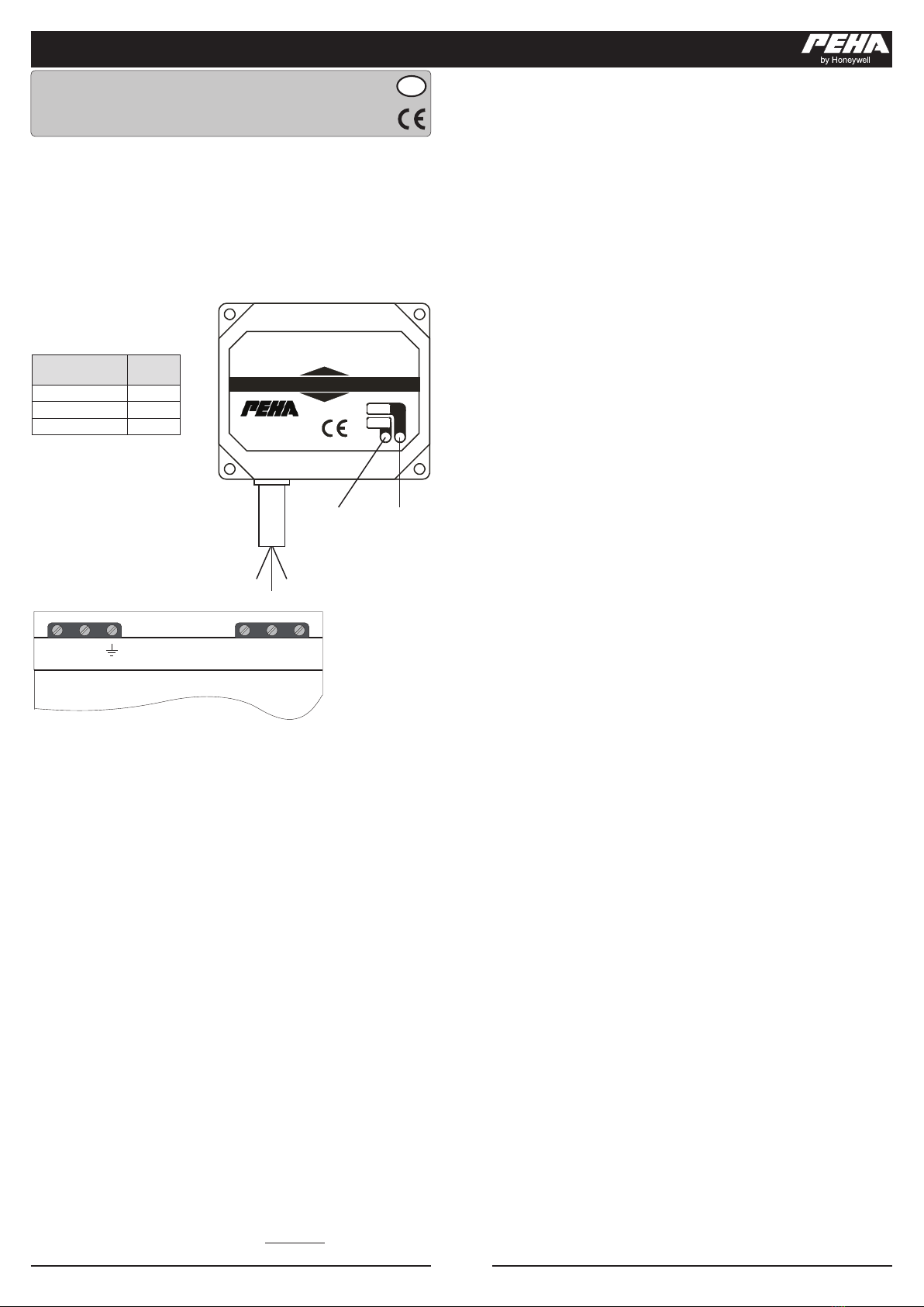
Der DCF Empfänger ist in einem Kunststoff-Spritzgußgehäuse montiert und wird über
ein dreiadriges Kabel an das Steuermodul 940 STM angeschlossen. Der Empfänger
besitzt eine Modulations- und ein Feld-stärke-LED. Durch den Anschluss des DCF-
Empfängers an die DCF-Klemme des PHC Steuermoduls 940 STM wird die interne
Uhr des Steuermoduls über Funk per DCF-Signal automatisch eingestellt. Damit
entfällt die manuelle Einstellung der Uhr. Nach ca. 5 Minuten erscheint die aktuelle
Zeit in der Anzeige des Steuermoduls.

Schraubklemme
 
0V braun
ANT. weiß
+5 V grün


DCF 77 - EMPFÄNGER
Senderrichtung (Frankfurt am Main)
251117
MOD.
FELD
941 DCF
-B +A
RS485 DCF
0V ANT. +5V
Steuermodul

 
 





Für den DCF-Empfänger ist ein Installationsort zu wählen, an dem ein ausreichender
Empfang des DCF-Signals vorhanden ist (s. Antennenausrichtung). Ist die Empfangs-
leistung des DCF-Signals sehr gering, kann es sein, dass die Funktion des DCF-
Emfängers beeinträchtigt ist und deshalb die interne Uhr des Steuermoduls nicht
mehr automatisch eingestellt wird.
Das Gehäuse verfügt über ein doppelseitiges Klebe-Pad für die Montage an glatten
Flächen (z.B. Möbel/Fenster). Als Zubehör ist ein verstellbarer Wandhalter erhältlich.
Die Installation des Anschlusskabels darf nicht parallel zu Schalt- oder Versorgungs-
leitungen erfolgen, sondern sollte einzeln ausgeführt werden, um Störungen des
Uhrenbausteins des PHC Steuermoduls zu vermeiden. Die verwendete Leitungslänge
des Anschlusskabels zwischen dem Steuermodul und dem DCF-Empfänger sollte nicht
mehr als maximal 3m betragen.

Die beste Empfangsleistung wird erzielt, wenn die Längsseite des DCF- Empfängers
(siehe Pfeilsymbol des Aufdrucks) in Senderrichtung (Frankfurt am Main) ausgerichtet
ist. Der DCF-Empfänger kann unter Beachtung der Feldstärke- und Modulations-LED
optimal zur Senderrichtung ausgerichtet werden. Eine praktische Vorgehensweise
besteht darin, zuerst die mini-male Feldstärke (Feldstärke LED dunkler) einzustellen
und danach durch langsame Drehung um ca. 90° in Längsrichtung den DCF-Empfänger
optimal zur Senderrichtung auszurichten (Feldstärke LED heller).
Eine helle Feldstärkeanzeige sagt noch nichts über die Empfangsqualität aus,
da auch eventuell Störsignale in der Empfangsbandbreite des Empfängers mit
ausgewertet werden. Vielmehr zeigt eine streng im Sekundentakt blinkende
Modulations-LED in Verbindung mit einer möglichst hellen Feldstärkeanzeige, dass
gute Empfangsverhältnisse vorliegen. Es sollte ein Abstand von möglichst mehreren
Metern zu Computer- oder Fernsehmonitoren, sowie mind. 30cm zu jeglichen
Metallgegenständen eingehalten werden.







GB

The DCF receiver is mounted in a plastic moulded housing and is connected by a
3-wire cable to the 940 STM control module. The receiver features a modulation and
a eld intensity LED. By connecting the DCF receiver to the DCF terminal of the PHC
control module 940 STM the internal clock of the control module is set automatically
via radio by DCF signal. Manual setting of the clock is thereby not needed. After about
5 minutes the current time appears in the display of the control module.


 
0V brown
ANT. white
+5 V green


DCF 77 - EMPFÄNGER
Senderrichtung (Frankfurt am Main)
251117
MOD.
FELD
941 DCF
-B +A
RS485 DCF
0V ANT. +5V
Steuermodul

 
  





For the DCF receiver an installation site needs to be selected at which there is sufcient
reception of the DCF signal available (s. antenna orientation). If the reception power of
the DCF signal very low then it may be that the function of the DCF receiver is impaired
and the internal clock of the control module is therefore no longer set automatically.
The housing features a double-sided adhesive pad for mounting on smooth surfaces
(e.g. furniture/windows). An adjustable wall holder is available as an auxiliary. The
installation of the connection cable may not be done parallel to the switching and
supply lines, but should be done individually to avoid malfunctions of the clock module
of the PHC control module. The line length of the connection cable between the control
module and the DCF receiver should not be longer than 3 metres.

The best reception power is achieved when the long side of the DCF receiver (refer
to arrow symbol on the label) points in the transmitter direction (Frankfurt am Main).
The DCF receiver can be oriented optimally to the transmitter direction while observing
the eld intensity and modulation LED. A practical procedure consists of rst setting
the minimum eld intensity (eld intensity LED darker) and then, by slowly turning by
90° in longitudinal direction, to orient the DCF receiver optimally to the transmitter
direction (eld intensity LED brighter).
A bright eld intensity display does not say anything about the reception quality,
because even possible interfering signals in the reception bandwidth of the receiver
are interpreted as well. Rather a modulation LED that is ashing at a steady rate of
one per second in connection with a bright as possible eld intensity indication that
the reception conditions are good. A distance of several metres if possible to computer
or television monitors as well as at least 30 cm to any metal objects should be kept.
PEHA_M_940_DCF (Rev04_130311)
PEHA Elektro GmbH & Co. KG

126008-04





De DCF-ontvanger is voorzien van een kunststof spuitgietbehuizing en wordt via een
3-aderige kabel op de stuurmodule 940 STM aangesloten. De ontvanger beschikt
over een LED voor de modulatie en een LED voor de veldsterkte. Wanneer de DCF-
ontvanger op de DCF-klem van de PHC-stuurmodule 940 STM wordt aangesloten,
wordt de interne klok van de stuurmodule via het DCF-signaal automatisch draadloos
ingesteld. Een handmatige instelling van de klok is dus niet nodig. Na ca. 5 minuten
verschijnt de actuele tijd op de display van de stuurmodule.

Schroefklem
 
0 V bruin
ANT. wit
+5 V groen


DCF 77 - EMPFÄNGER
Senderrichtung (Frankfurt am Main)
251117
MOD.
FELD
941 DCF
-B +A
RS485 DCF
0V ANT. +5V
Steuermodul

 
 





De DCF-ontvanger dient te worden geïnstalleerd op een plaats waar het DCF-signaal
goed wordt ontvangen (zie Uitrichten van de antenne). Wanneer het ontvangst-
vermogen van het DCF-signaal erg klein, is het mogelijk dat de DCF-ontvanger niet
goed functioneert en dat de interne klok van de stuurmodule niet meer automatisch
wordt ingesteld.
De behuizing is voorzien van een dubbelzijdige plakstrip voor montage op gladde
oppervlakken (bijv. meubels/vensters). Als toebehoren is een verstelbare wandhouder
verkrijgbaar. De aansluitkabel mag niet parallel aan schakel- of voedingskabels worden
geïnstalleerd, maar moet afzonderlijk worden gelegd om storing van de klokcomponent
van de PHC-stuurmodule te voorkomen. De lengte van de aansluitkabel tussen de
stuurmodule en de DCF-ontvanger mag niet meer zijn dan 3 meter.

Het beste ontvangstvermogen wordt bereikt wanneer de lange zijde van de DCF-
ontvanger (zie pijlsymbool van de opdruk) in de richting van de zender (Frankfurt am
Main) wijst. Met de LED‘s voor veldsterkte en modulatie kan de DCF-ontvanger optimaal
naar de zender worden uitgericht. Dit kan praktisch worden uitgevoerd door eerst de
minimale veldsterkte in te stellen (de LED voor de veldsterkte brandt minimaal) en
vervolgens de DCF-ontvanger langzaam ca. 90° in de lengterichting te draaien (de
LED voor de veldsterkte gaat feller branden).
Een felle LED voor de veldsterkte zegt echter nog niets over de ontvangstkwaliteit,
omdat er in de ontvangstbandbreedte van de ontvanger ook stoorsignalen kunnen
worden meegenomen. Wanneer de LED voor de modulatie elke seconde knippert en
de LED voor de veldsterkte fel brandt, wijst dit op een goede ontvangstkwaliteit. Er
dient een afstand van enkele meters tot PC- of TV-monitoren te worden aangehouden
en een minimale afstand van 30 cm tot metalen onderdelen.
PEHA Elektro B.V.
Pieter Calandweg 58 • 6827 BK Arnhem • Internet: www.peha.de

Other PEHA Receiver manuals

PEHA enocean Easyclick Plus 451 FU-BEP DAB User manual

PEHA

PEHA enocean Easyclick Plus 451 FU-BEP DAB User manual

PEHA 451 FU-EP UP o.A. User manual

PEHA

PEHA 451 FU-EP UP o.A. User manual

PEHA 454 FU-E REG User manual

PEHA

PEHA 454 FU-E REG User manual

PEHA 452 FU-EP JR UP o.A. User manual

PEHA

PEHA 452 FU-EP JR UP o.A. User manual

PEHA 454 FU-E DE User manual

PEHA

PEHA 454 FU-E DE User manual

PEHA Easyclick Plus 452 FU-EP JR o.T User manual

PEHA

PEHA Easyclick Plus 452 FU-EP JR o.T User manual

PEHA Easyclick Series User manual

PEHA

PEHA Easyclick Series User manual

PEHA Easyclick 452 FU-E JR o.T. User manual

PEHA

PEHA Easyclick 452 FU-E JR o.T. User manual

PEHA Easyclick 451 FU-E o.T. User manual

PEHA

PEHA Easyclick 451 FU-E o.T. User manual

Popular Receiver manuals by other brands

Pioneer DVH-3150UB Operation manual

Pioneer

Pioneer DVH-3150UB Operation manual

MSB Technology SAROWIN HD-10 user manual

MSB Technology

MSB Technology SAROWIN HD-10 user manual

Philips DTR300/00 user manual

Philips

Philips DTR300/00 user manual

Shure GLXD4R+ manual

Shure

Shure GLXD4R+ manual

Jameson JS-315BT user manual

Jameson

Jameson JS-315BT user manual

Crestron CNRFGWA Operation guide

Crestron

Crestron CNRFGWA Operation guide

Garmin 190-00336-00 owner's manual

Garmin

Garmin 190-00336-00 owner's manual

Kenwood KRF-V8881 D instruction manual

Kenwood

Kenwood KRF-V8881 D instruction manual

Ocean Digital IRT-01C user manual

Ocean Digital

Ocean Digital IRT-01C user manual

Mantracourt T24-ANTA user manual

Mantracourt

Mantracourt T24-ANTA user manual

Velleman AVMOD15 manual

Velleman

Velleman AVMOD15 manual

Yamaha RX-A1010 Easy setup guide

Yamaha

Yamaha RX-A1010 Easy setup guide

Aiwa CR-LD100M2 Service manual

Aiwa

Aiwa CR-LD100M2 Service manual

Orava DVB-30 manual

Orava

Orava DVB-30 manual

Spektrum DX3S user guide

Spektrum

Spektrum DX3S user guide

Onkyo HT-RC630 Service manual

Onkyo

Onkyo HT-RC630 Service manual

Integra DTR-4.9 Service manual

Integra

Integra DTR-4.9 Service manual

Philips HTS3105MKI98 Service manual

Philips

Philips HTS3105MKI98 Service manual

manuals.online logo
manuals.online logoBrands
  • About & Mission
  • Contact us
  • Privacy Policy
  • Terms and Conditions

Copyright 2025 Manuals.Online. All Rights Reserved.