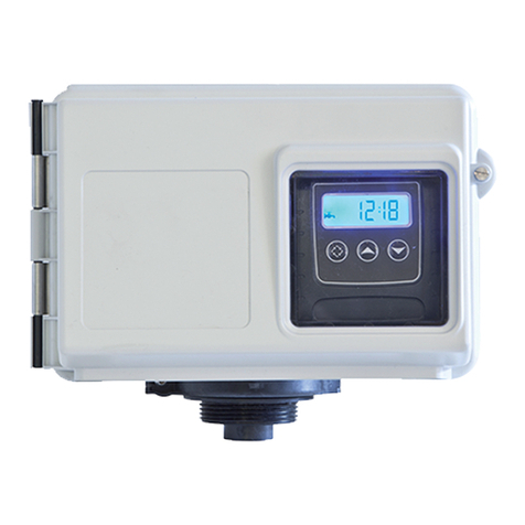
Pentair Keystone Figure 952 NPS 2 Installation instructions
Other Pentair Control Unit manuals
Pentair
Pentair FLECK 9000 SXT User guide

Pentair
Pentair Fleck 2850 NXT User guide
Pentair
Pentair AURORA CBV-S/A User manual
Pentair
Pentair FLECK 3150 NXT User guide

Pentair
Pentair Autotrol 255 Series User guide

Pentair
Pentair F783E User manual
Pentair
Pentair AUTOTROL 742 Series User manual

Pentair
Pentair SIATA V132 SFE-EV VIRIDION User manual

Pentair
Pentair AUTOTROL Performa 263 User guide

Pentair
Pentair FLECK NXT User manual
Pentair
Pentair AURORA CBV-S5 User manual

Pentair
Pentair EVERPURE MRS-350BL User manual

Pentair
Pentair AUTOTROL 604 User guide

Pentair
Pentair FLECK 3900 User manual

Pentair
Pentair PERFORMA CV Series User manual
Pentair
Pentair TRACETEK TTDM-128 User manual

Pentair
Pentair FLECK 4600 SXT User manual

Pentair
Pentair ERICO CADWELD PLUS User manual

Pentair
Pentair Fleck 5600-MECH User manual

Pentair
Pentair FLECK 3150 NXT User guide
Popular Control Unit manuals by other brands

Festo
Festo Compact Performance CP-FB6-E Brief description

Elo TouchSystems
Elo TouchSystems DMS-SA19P-EXTME Quick installation guide

JS Automation
JS Automation MPC3034A user manual

JAUDT
JAUDT SW GII 6406 Series Translation of the original operating instructions

Spektrum
Spektrum Air Module System manual

BOC Edwards
BOC Edwards Q Series instruction manual

KHADAS
KHADAS BT Magic quick start

Etherma
Etherma eNEXHO-IL Assembly and operating instructions

PMFoundations
PMFoundations Attenuverter Assembly guide

GEA
GEA VARIVENT Operating instruction

Walther Systemtechnik
Walther Systemtechnik VMS-05 Assembly instructions

Altronix
Altronix LINQ8PD Installation and programming manual
