manuals.online logo
Brands
  1. Home
  2. •
  3. Brands
  4. •
  5. Pepperl+Fuchs
  6. •
  7. Accessories
  8. •
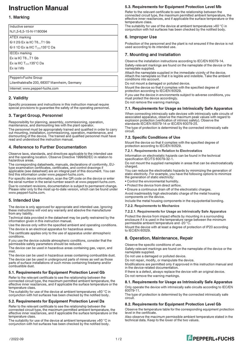
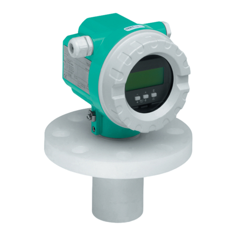
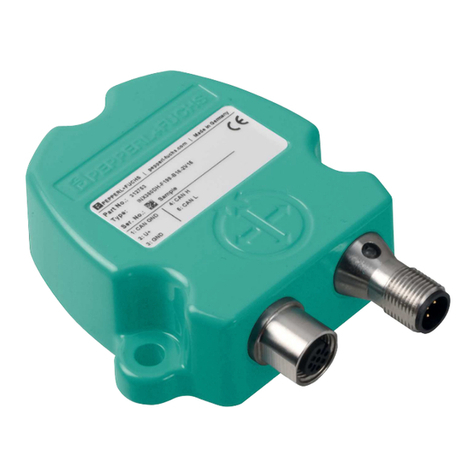
  9. Pepperl+Fuchs NCN4-12GM35-N0 User manual

Pepperl+Fuchs NCN4-12GM35-N0 User manual

Instruction Manual
1. Marking
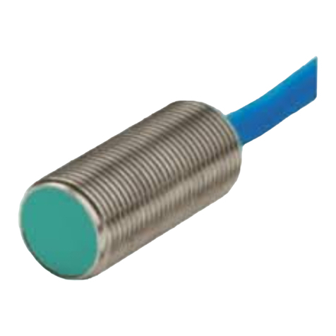
Inductive sensor
NCN4-12GM35-N0
ATEX marking
1 II 1G Ex ia IIC T6...T1 Ga
1 II 3G Ex ic IIC T6...T1 Gc
1 II 1D Ex ia IIIC T135°C Da
1 II 3D Ex tc IIIC T80°C Dc
IECEx marking
Ex ia IIC T6...T1 Ga
Ex ia IIIC T135°C Da
Ex ia I Mb
Pepperl+Fuchs Group
Lilienthalstraße 200, 68307 Mannheim, Germany
Internet: www.pepperl-fuchs.com
2. Validity
Specific processes and instructions in this instruction manual require
special provisions to guarantee the safety of the operating personnel.
3. Target Group, Personnel
Responsibility for planning, assembly, commissioning, operation,
maintenance, and dismounting lies with the plant operator.
The personnel must be appropriately trained and qualified in order to carry
out mounting, installation, commissioning, operation, maintenance, and
dismounting of the device. The trained and qualified personnel must have
read and understood the instruction manual.
4. Reference to Further Documentation
Observe laws, standards, and directives applicable to the intended use
and the operating location. Observe Directive 1999/92/EC in relation to
hazardous areas.
The corresponding datasheets, manuals, declarations of conformity, EU-
type examination certificates, certificates, and control drawings if
applicable (see datasheet) are an integral part of this document. You can
find this information under www.pepperl-fuchs.com.
Due to constant revisions, documentation is subject to permanent change.
Please refer only to the most up-to-date version, which can be found under
www.pepperl-fuchs.com.
5. Intended Use
The device is only approved for appropriate and intended use. Ignoring
these instructions will void any warranty and absolve the manufacturer
from any liability.
Technical data provided in the datasheet may be partly restrained by the
information given in this instruction manual.
Use the device only within the specified ambient and operating conditions.
The device is an electrical apparatus for hazardous areas.
The certificate applies only to the use of apparatus under atmospheric
conditions.
If you use the device outside atmospheric conditions, consider that the
permissible safety parameters should be reduced.
The device can be used in hazardous areas containing gas, vapor, and
mist.
The device can be used in hazardous areas containing combustible dust.
The device can be used in underground parts of mines as well as those
parts of surface installations of such mines containing firedamp and/or
combustible dust.
5.1. Requirements for Equipment Protection Level Ga
Refer to the relevant certificate to see the relationship between the
connected circuit type, the maximum permitted ambient temperature, the
effective inner reactances, and if applicable the surface temperature or the
temperature class.
The suitability for use of the device at ambient temperatures >60 °C in
conjunction with hot surfaces has been checked by the notified body.
For usage as apparatus according to ATEXDirective, the temperature
reduction of 20 % according to EN 1127-1 was taken into account in the
temperature table for the corresponding equipment protection level.
5.2. Requirements for Equipment Protection Level Gb
Refer to the relevant certificate to see the relationship between the
connected circuit type, the maximum permitted ambient temperature, the
effective inner reactances, and if applicable the surface temperature or the
temperature class.
The suitability for use of the device at ambient temperatures >60 °C in
conjunction with hot surfaces has been checked by the notified body.
5.3. Requirements for Equipment Protection Level Da
Refer to the relevant certificate to see the relationship between the
connected circuit type, the maximum permitted ambient temperature, the
effective inner reactances, and if applicable the surface temperature or the
temperature class.
The suitability for use of the device at ambient temperatures >60 °C in
conjunction with hot surfaces has been checked by the notified body.
5.4. Requirements for Equipment Protection Level Mb
Refer to the relevant certificate to see the relationship between the
connected circuit type, the maximum permitted ambient temperature, the
effective inner reactances, and if applicable the surface temperature or the
temperature class.
The suitability for use of the device at ambient temperatures >60 °C in
conjunction with hot surfaces has been checked by the notified body.
6. Improper Use
Protection of the personnel and the plant is not ensured if the device is not
used according to its intended use.
7. Mounting and Installation
Observe the installation instructions according to IEC/EN 60079-14.
Safety-relevant markings are found on the nameplate of the device or the
nameplate supplied.
Attach the nameplate supplied in the immediate vicinity of the device.
Attach the nameplate so that it is legible and indelible. Take the ambient
conditions into account.
Do not mount a damaged or polluted device.
Mount the device so that it complies with the specified degree of
protection according to IEC/EN 60529.
If you use the device in environments subject to adverse conditions, you
must protect the device accordingly.
Do not remove the warning markings.
7.1. Requirements for Usage as Intrinsically Safe Apparatus
When connecting intrinsically safe devices with intrinsically safe circuits of
associated apparatus, observe the maximum peak values with regard to
explosion protection (verification of intrinsic safety). Observe the
standards IEC/EN 60079-14 or IEC/EN 60079-25.
The type of protection is determined by the connected intrinsically safe
circuit.
Mount the device with at least a degree of protection of IP20 according
to IEC/EN 60529.
7.2. Requirements for Equipment Protection Level Dc
Install a series resistor RV between the supply voltage and the device.
Alternatively, use a switch amplifier according to IEC/EN 60947-5-6.
When selecting materials for accessories consider that the temperature of
the housing can rise up to 70 °C.
The maximum surface temperature of the device was determined without
a dust layer on the apparatus.
7.3. Specific Conditions of Use
Mount the device so that it complies with the specified degree of
protection according to IEC/EN 60529.
7.3.1. Requirements in Relation to Electrostatics
Information on electrostatic hazards can be found in the technical
specification IEC/TS 60079-32-1.
Do not mount the supplied nameplate in areas that can be electrostatically
charged.
Avoid inadmissibly high electrostatic charge of the metal housing
components on the device.
Include the metal housing components in the equipotential bonding.
7.3.2. Requirements to Mechanics
7.3.2.1. Requirements for Usage as Intrinsically Safe Apparatus
Protect the device from impact effects by mounting in a surrounding
enclosure if it is used in the temperature range between the minimum
permissible ambient temperature and -20 °C.
Mount the device with at least a degree of protection of IP20 according
to IEC/EN 60529.
7.3.2.2. Requirements for Equipment Protection Level Dc
Mount the device in a way that the device is protected against mechanical
hazard.
/ 2020-08 1 / 4
7.3.3. Requirements in Relation to Ultraviolet Radiation
7.3.3.1. Requirements for Equipment Protection Level Dc
Mount the device in such a way that it is protected from ultraviolet
radiation.
Install the cables and connection lines in such a way that they are
protected from ultraviolet radiation.
8. Operation, Maintenance, Repair
Observe the specific conditions of use.
Safety-relevant markings are found on the nameplate of the device or the
nameplate supplied.
Do not use a damaged or polluted device.
Do not repair, modify, or manipulate the device.
Modifications are permitted only if approved in this instruction manual and
in the device-related documentation.
If there is a defect, always replace the device with an original device.
Do not remove the warning markings.
8.1. Requirements for Usage as Intrinsically Safe Apparatus
Only operate the device with intrinsically safe circuits according to IEC/EN
60079-11.
The type of protection is determined by the connected intrinsically safe
circuit.
8.2. Requirements for Equipment Protection Level Ga
Observe the temperature table for the corresponding equipment protection
level in the certificate.
Also observe the maximum permissible ambient temperature stated in the
technical data. Keep to the lower of the two values.
8.3. Requirements for Equipment Protection Level Gb
Observe the temperature table for the corresponding equipment protection
level in the certificate.
Also observe the maximum permissible ambient temperature stated in the
technical data. Keep to the lower of the two values.
8.4. Requirements for Equipment Protection Level Da
Observe the temperature table for the corresponding equipment protection
level in the certificate.
Also observe the maximum permissible ambient temperature stated in the
technical data. Keep to the lower of the two values.
8.5. Requirements for Equipment Protection Level Dc
Do not exceed the maximum permissible operating voltage Ubmax.
Tolerances are not permitted.
Do not exceed the maximum permitted output current. Prevent short
circuits.
8.6. Requirements for Equipment Protection Level Mb
Observe the temperature table for the corresponding equipment protection
level in the certificate.
Also observe the maximum permissible ambient temperature stated in the
technical data. Keep to the lower of the two values.
9. Delivery, Transport, Disposal
Check the packaging and contents for damage.
Check if you have received every item and if the items received are the
ones you ordered.
Keep the original packaging. Always store and transport the device in the
original packaging.
Store the device in a clean and dry environment. The permitted ambient
conditions must be considered, see datasheet.
The device, built-in components, packaging, and any batteries contained
within must be disposed in compliance with the applicable laws and
guidelines of the respective country.
10. National Ex approvals
EAC-EX: TC RU C-DE.AA87.B.00394
UL HAZLOC: E501628
116-0452
KCC-EX: 09-AV4BO-0225/0226/0227
TIIS-EX: TC16074
ANZEx: ANZEx 18.3018X
11. Safety-Relevant Technical Data
11.1. Equipment protection level Ga
Type of protection Intrinsic safety
CE marking 2-0102
Certificates
Appropriate type NCN4-12GM...-N0...
ATEX certificate PTB 00 ATEX 2048 X
ATEX marking 1 II 1G Ex ia IIC T6...T1 Ga
ATEX standards EN 60079-0:2012-08, EN
60079-0/A11:2013-11, EN
60079-11:2012-01
IECEx certificate IECEx PTB 11.0037X
IECEx marking Ex ia IIC T6...T1 Ga
IECEx standards IEC 60079-0:2011-06, IEC
60079-11:2011-06
Effective internal
capacitance Ci
max. 95 nF
A cable length of 10 m is considered.
Effective internal
inductance Li
max. 100 µH
A cable length of 10 m is considered.
Maximum permissible
ambient temperature in °C
Also observe the maximum permissible
ambient temperature stated in the general
technical data. Keep to the lower of the two
values.
for ATEX Ui = 16 V, Ii = 25 mA, Pi = 34 mW
T6: 59 °C
T5: 71 °C
T4: 99 °C
T3: 99 °C
T2: 99 °C
T1: 99 °C
Ui = 16 V, Ii = 25 mA, Pi = 64 mW
T6: 56 °C
T5: 68 °C
T4: 96 °C
T3: 96 °C
T2: 96 °C
T1: 96 °C
Ui = 16 V, Ii = 52 mA, Pi = 169 mW
T6: 45 °C
T5: 57 °C
T4: 81 °C
T3: 81 °C
T2: 81 °C
T1: 81 °C
Ui = 16 V, Ii = 76 mA, Pi = 242 mW
T6: 37 °C
T5: 49 °C
T4: 63 °C
T3: 63 °C
T2: 63 °C
T1: 63 °C
/ 2020-08 2 / 4
for IECEx Ui = 16 V, Ii = 25 mA, Pi = 34 mW
T6: 76 °C
T5: 91 °C
T4: 100 °C
T3: 100 °C
T2: 100 °C
T1: 100 °C
Ui = 16 V, Ii = 25 mA, Pi = 64 mW
T6: 73 °C
T5: 88 °C
T4: 100 °C
T3: 100 °C
T2: 100 °C
T1: 100 °C
Ui = 16 V, Ii = 52 mA, Pi = 169 mW
T6: 62 °C
T5: 77 °C
T4: 81 °C
T3: 81 °C
T2: 81 °C
T1: 81 °C
Ui = 16 V, Ii = 76 mA, Pi = 242 mW
T6: 54 °C
T5: 63 °C
T4: 63 °C
T3: 63 °C
T2: 63 °C
T1: 63 °C
11.2. Equipment protection level Gb
Type of protection Intrinsic safety
CE marking 2-0102
Certificates
Appropriate type NCN4-12GM...-N0...
ATEX certificate PTB 00 ATEX 2048 X
ATEX marking 1 II 1G Ex ia IIC T6...T1 Ga
ATEX standards EN 60079-0:2012-08, EN
60079-0/A11:2013-11, EN
60079-11:2012-01
IECEx certificate IECEx PTB 11.0037X
IECEx marking Ex ia IIC T6...T1 Ga
IECEx standards IEC 60079-0:2011-06, IEC
60079-11:2011-06
Effective internal
capacitance Ci
max. 95 nF
A cable length of 10 m is considered.
Effective internal
inductance Li
max. 100 µH
A cable length of 10 m is considered.
Maximum permissible
ambient temperature in °C
Also observe the maximum permissible
ambient temperature stated in the general
technical data. Keep to the lower of the two
values.
Ui = 16 V, Ii = 25 mA, Pi = 34 mW
T6: 76 °C
T5: 91 °C
T4: 100 °C
T3: 100 °C
T2: 100 °C
T1: 100 °C
Ui = 16 V, Ii = 25 mA, Pi = 64 mW
T6: 73 °C
T5: 88 °C
T4: 100 °C
T3: 100 °C
T2: 100 °C
T1: 100 °C
Ui = 16 V, Ii = 52 mA, Pi = 169 mW
T6: 62 °C
T5: 77 °C
T4: 81 °C
T3: 81 °C
T2: 81 °C
T1: 81 °C
Ui = 16 V, Ii = 76 mA, Pi = 242 mW
T6: 54 °C
T5: 63 °C
T4: 63 °C
T3: 63 °C
T2: 63 °C
T1: 63 °C
11.3. Equipment protection level Gc (ic)
Type of protection Intrinsic safety
CE marking 2
Certificates
ATEX certificate PF13CERT2895X
ATEX marking 1 II 3G Ex ic IIC T6...T1 Gc
ATEX standards EN 60079-0:2012-08, EN
60079-0/A11:2013-11, EN
60079-11:2012-01
Effective internal
capacitance Ci
max. 95 nF
A cable length of 10 m is considered.
Effective internal
inductance Li
max. 100 µH
A cable length of 10 m is considered.
/ 2020-08 3 / 4
Maximum permissible
ambient temperature in °C
Also observe the maximum permissible
ambient temperature stated in the general
technical data. Keep to the lower of the two
values.
Ui = 20 V, Ii = 25 mA, Pi = 34 mW
T6: 55 °C
T5: 55 °C
T4: 55 °C
T3: 55 °C
T2: 55 °C
T1: 55 °C
Ui = 20 V, Ii = 25 mA, Pi = 64 mW
T6: 55 °C
T5: 55 °C
T4: 55 °C
T3: 55 °C
T2: 55 °C
T1: 55 °C
Ui = 20 V, Ii = 52 mA, Pi = 169 mW
T6: 52 °C
T5: 52 °C
T4: 52 °C
T3: 52 °C
T2: 52 °C
T1: 52 °C
Ui = 20 V, Ii = 76 mA, Pi = 242 mW
T6: 44 °C
T5: 44 °C
T4: 44 °C
T3: 44 °C
T2: 44 °C
T1: 44 °C
11.4. Equipment protection level Da
Type of protection Intrinsic safety
CE marking 2-0102
Certificates
Appropriate type NCN4-12GM...-N0...
ATEX certificate PTB 00 ATEX 2048 X
ATEX marking 1 II 1D Ex ia IIIC T135°C Da
ATEX standards EN 60079-0:2012-08, EN
60079-0/A11:2013-11, EN
60079-11:2012-01
IECEx certificate IECEx PTB 11.0037X
IECEx marking Ex ia IIIC T135°C Da
IECEx standards IEC 60079-0:2011-06, IEC
60079-11:2011-06
Effective internal
capacitance Ci
max. 95 nF
A cable length of 10 m is considered.
Effective internal
inductance Li
max. 100 µH
A cable length of 10 m is considered.
Maximum permissible
ambient temperature in °C
Also observe the maximum permissible
ambient temperature stated in the general
technical data. Keep to the lower of the two
values.
Ui = 16 V, Ii = 25 mA, Pi = 34 mW
100 °C
Ui = 16 V, Ii = 25 mA, Pi = 64 mW
100 °C
Ui = 16 V, Ii = 52 mA, Pi = 169 mW
81 °C
Ui = 16 V, Ii = 76 mA, Pi = 242 mW
63 °C
11.5. Equipment protection level Dc
Type of protection Protection by enclosure "tc"
CE marking 2
Certificates
ATEX certificate PF15CERT3774X
ATEX marking 1 II 3D Ex tc IIIC T80°C Dc
ATEX standards EN 60079-0:2012-08, EN
60079-0/A11:2013-11, EN
60079-31:2014-07
Maximum permissible
ambient temperature in °C
Also observe the maximum permissible
ambient temperature stated in the general
technical data. Keep to the lower of the two
values.
Maximum operating voltage UBmax
Maximum load current ILmax
Minimum series resistance RV
Maximum analog output voltage UAmax
Maximum analog output current IAmax
at UBmax = 9 V, RV = 562 Ohm: 61 °C
using an amplifier in accordance with EN
60947-5-6: 61 °C
11.6. Equipment protection level Mb
Type of protection Intrinsic safety
Certificates
Appropriate type NCN4-12GM...-N0...
IECEx certificate IECEx PTB 11.0037X
IECEx marking Ex ia I Mb
IECEx standards IEC 60079-0:2011-06, IEC
60079-11:2011-06
Effective internal
capacitance Ci
max. 95 nF
A cable length of 10 m is considered.
Effective internal
inductance Li
max. 100 µH
A cable length of 10 m is considered.
Maximum permissible
ambient temperature in °C
Also observe the maximum permissible
ambient temperature stated in the general
technical data. Keep to the lower of the two
values.
Ui = 16 V, Ii = 25 mA, Pi = 34 mW
100 °C
Ui = 16 V, Ii = 25 mA, Pi = 64 mW
100 °C
Ui = 16 V, Ii = 52 mA, Pi = 169 mW
81 °C
Ui = 16 V, Ii = 76 mA, Pi = 242 mW
63 °C
/ 2020-08 4 / 4

Other Pepperl+Fuchs Accessories manuals

Pepperl+Fuchs NVF-112-0400 User manual

Pepperl+Fuchs

Pepperl+Fuchs NVF-112-0400 User manual

Pepperl+Fuchs RMS-D Reference guide

Pepperl+Fuchs

Pepperl+Fuchs RMS-D Reference guide

Pepperl+Fuchs OIT500-F113-B17-CB User manual

Pepperl+Fuchs

Pepperl+Fuchs OIT500-F113-B17-CB User manual

Pepperl+Fuchs TopScan-S User manual

Pepperl+Fuchs

Pepperl+Fuchs TopScan-S User manual

Pepperl+Fuchs ML300-P-6m-RT/25 User manual

Pepperl+Fuchs

Pepperl+Fuchs ML300-P-6m-RT/25 User manual

Pepperl+Fuchs UC500-L2-E4-V15 User manual

Pepperl+Fuchs

Pepperl+Fuchs UC500-L2-E4-V15 User manual

Pepperl+Fuchs SU17 Series User manual

Pepperl+Fuchs

Pepperl+Fuchs SU17 Series User manual

Pepperl+Fuchs NCB4-12GM40-N0-V1 User manual

Pepperl+Fuchs

Pepperl+Fuchs NCB4-12GM40-N0-V1 User manual

Pepperl+Fuchs ML7-55 User manual

Pepperl+Fuchs

Pepperl+Fuchs ML7-55 User manual

Pepperl+Fuchs SmartRunner Explorer User manual

Pepperl+Fuchs

Pepperl+Fuchs SmartRunner Explorer User manual

Pepperl+Fuchs IPT FP Series User manual

Pepperl+Fuchs

Pepperl+Fuchs IPT FP Series User manual

Pepperl+Fuchs GLV18-8-200/73/120 User manual

Pepperl+Fuchs

Pepperl+Fuchs GLV18-8-200/73/120 User manual

Pepperl+Fuchs NJ15-30GM50-E2-V1-3G-3D User manual

Pepperl+Fuchs

Pepperl+Fuchs NJ15-30GM50-E2-V1-3G-3D User manual

Pepperl+Fuchs NCB20-L2-N0-V1 User manual

Pepperl+Fuchs

Pepperl+Fuchs NCB20-L2-N0-V1 User manual

Pepperl+Fuchs 6GR6241-7BB00-PF User manual

Pepperl+Fuchs

Pepperl+Fuchs 6GR6241-7BB00-PF User manual

Pepperl+Fuchs MLV41-8-HV-60-IR/110/124/167 User manual

Pepperl+Fuchs

Pepperl+Fuchs MLV41-8-HV-60-IR/110/124/167 User manual

Pepperl+Fuchs OPC User manual

Pepperl+Fuchs

Pepperl+Fuchs OPC User manual

Pepperl+Fuchs UC500-30GM-IUEP-IO-V15 User manual

Pepperl+Fuchs

Pepperl+Fuchs UC500-30GM-IUEP-IO-V15 User manual

Pepperl+Fuchs UC2000-L2-E7-V15 User manual

Pepperl+Fuchs

Pepperl+Fuchs UC2000-L2-E7-V15 User manual

Pepperl+Fuchs UB250-F77-E2-V31 Guide

Pepperl+Fuchs

Pepperl+Fuchs UB250-F77-E2-V31 Guide

Pepperl+Fuchs LVL-Z121 User manual

Pepperl+Fuchs

Pepperl+Fuchs LVL-Z121 User manual

Pepperl+Fuchs VIM6 Series User manual

Pepperl+Fuchs

Pepperl+Fuchs VIM6 Series User manual

Pepperl+Fuchs UC500-30GM-2EP-IO-V15 User manual

Pepperl+Fuchs

Pepperl+Fuchs UC500-30GM-2EP-IO-V15 User manual

Pepperl+Fuchs U-P R4 Series User manual

Pepperl+Fuchs

Pepperl+Fuchs U-P R4 Series User manual

Popular Accessories manuals by other brands

Balluff BOD 37M-LPR02-S115 user guide

Balluff

Balluff BOD 37M-LPR02-S115 user guide

Spectris Particle Measuring Systems LiQuilaz II E Operation manual

Spectris

Spectris Particle Measuring Systems LiQuilaz II E Operation manual

Hytronik HIR23 Installation and instruction manual

Hytronik

Hytronik HIR23 Installation and instruction manual

nedis WIFIP130FWT3 quick start guide

nedis

nedis WIFIP130FWT3 quick start guide

Uclear HBC 100 PLUS user manual

Uclear

Uclear HBC 100 PLUS user manual

ANSMANN POWERBANK 10.0 manual

ANSMANN

ANSMANN POWERBANK 10.0 manual

Nodis ZEN1 user manual

Nodis

Nodis ZEN1 user manual

American Standard Boulevard Wood Finish Toilet Seats 5314.110 Specifications

American Standard

American Standard Boulevard Wood Finish Toilet Seats 5314.110 Specifications

Moleskine PenPlus Ellipse NWP-F70 user manual

Moleskine

Moleskine PenPlus Ellipse NWP-F70 user manual

Gira 5472 02 operating instructions

Gira

Gira 5472 02 operating instructions

Markilux Syncra uno Mounting instructions

Markilux

Markilux Syncra uno Mounting instructions

Kogan SMARTERHOME KA2KVDBELA user guide

Kogan

Kogan SMARTERHOME KA2KVDBELA user guide

Moeller Xcomfort CSEZ-01/11 Assembly instructions

Moeller

Moeller Xcomfort CSEZ-01/11 Assembly instructions

Terra MMH3000 user manual

Terra

Terra MMH3000 user manual

Schmidt SS 20.225 Instructions for use

Schmidt

Schmidt SS 20.225 Instructions for use

ITW VORTEC PANEL GUARD 701 Operation & Safety Instructions

ITW

ITW VORTEC PANEL GUARD 701 Operation & Safety Instructions

Clearaudio TT1 MI user manual

Clearaudio

Clearaudio TT1 MI user manual

American Dynamics AD2091 Specifications

American Dynamics

American Dynamics AD2091 Specifications

manuals.online logo
manuals.online logoBrands
  • About & Mission
  • Contact us
  • Privacy Policy
  • Terms and Conditions

Copyright 2025 Manuals.Online. All Rights Reserved.