3
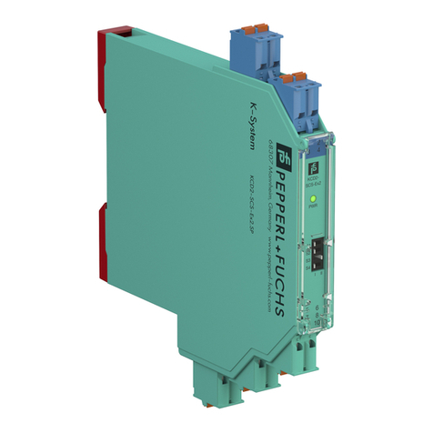
Fieldbus Valve Coupler FD0-VC-Ex4.FF
Table of contents
Subject to reasonable modifications due to technical advances. Copyright Pepperl+Fuchs, Printed in Germany
Pepperl+Fuchs Group •Tel.:Germany +49 621 776-0 • USA +1 330 4253555 • Singapore +65 67799091 • Internet http://www.pepperl-fuchs.com
Part No.: 108227, Date of issue 27.03.2006
Table of contents
1 SYMBOLS USED IN THIS MANUAL ..........................................................................................5
2 INTRODUCTION ....................................................................................................................7
2.1 Purpose of manual ......................................................................................................................................7
3 GENERAL INFORMATION .......................................................................................................9
3.1 Intended use .................................................................................................................................................9
3.2 Responsibilities of the user ......................................................................................................................10
3.3 Safety instructions ....................................................................................................................................10
3.4 Marking .......................................................................................................................................................10
4 PRODUCT DESCRIPTION .....................................................................................................11
4.1 Delivery package .......................................................................................................................................11
4.2 System structure .......................................................................................................................................11
4.2.1 Device description .......................................................................................................................................12
4.2.2 Auxiliary valves which can be connected ....................................................................................................13
4.2.3 Final position feedback contacts which can be connected ..........................................................................13
4.2.4 Description of 2:1 procedure ........................................................................................................................13
4.3 Accessories ................................................................................................................................................14
5 INSTALLATION ...................................................................................................................17
5.1 Storage and transportation .......................................................................................................................17
5.2 Unpacking ..................................................................................................................................................17
5.3 Mounting .....................................................................................................................................................17
5.4 Electrical connection .................................................................................................................................19
5.4.1 General notes for connection .......................................................................................................................19
5.4.2 Connection of fieldbus and DIP switch settings ...........................................................................................20
5.4.3 Connection of auxiliary valves and final position feedback contacts ...........................................................21
5.4.4 EMC, screening, grounding .........................................................................................................................22
5.5 Dismantling, packing and disposal ..........................................................................................................22
6 PARAMETERISATION AND OPERATION OF THE VALVE COUPLER ...........................................23
6.1 Introduction ................................................................................................................................................23
6.2 Identification, device ID .............................................................................................................................24
6.3 Interaction of the transducer blocks and the DO function blocks ........................................................24
6.4 Interaction of the transducer blocks and the DI function block ............................................................25
6.5 Parameterisation of transducer blocks ...................................................................................................27
6.5.1 Prerequisite ..................................................................................................................................................27
6.5.2 For commissioning proceed as follows: .......................................................................................................28
6.5.3 Drive design .................................................................................................................................................30
6.5.4 Final position feedback ................................................................................................................................30
6.5.5 Target mode ................................................................................................................................................33
6.5.6 Time monitoring ...........................................................................................................................................33
