PERCo ST-02 Series User manual

perco.com linkedin.com/mwlite/company/perco [email protected] +7 (812) 247-04-64
ST-02 Speed gate
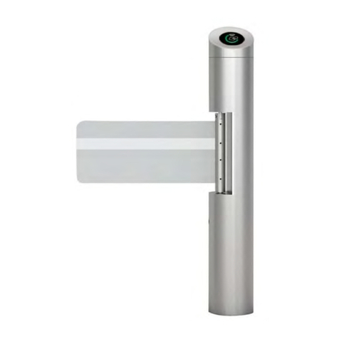
ST-02 Speed gate with sliding panels is designed for indoor operation. It is an ideal solution
for sites with high aesthetic and comfort requirements.
ST-02 is available in two versions: a standard passageway width of 600 mm (ST-02.600 version)
or an extended one of 900 mm (ST-02.900). The extended version provides convenient access
for people in wheelchairs and ensures free passage in case of an emergency. The panels are
sliding away when a passage takes place.
If an increased number of passage lanes is needed, STD-02 double-sided sections can be
installed. Each double-sided section allows arranging one extra passage lane. STD-02 is
available in two main versions: STD-02.600 and STD-02.900 for organizing passage lanes
with a width of 600 mm and 900 mm, respectively.
Application
Operating modes
RC-panel
The speed gate supports two main operating modes: normally closed and normally open, as
well as an additional "Automatic opening in the selected direction" mode (only in normally
closed mode).
Control commands:
•passage denial,
•authorized single passage in the set direction
•authorized free passage in the set direction
•authorized free passage in both directions
When the power is off, the sliding panels are unlocked and can be moved away manually.
•operation of the speed gate from RC-panel, WRC, ACS
•built into the housing electronic boards
•safe voltage – 24 V
ST-02.600/900 is available on a separate order to arrange
passage lanes of different widths (600 and 900 mm). For the same
purpose, the STD-02.900 double-sided section has the possibility of
reducing one panel to 600 mm.
The tracking system is equipped with two levels of infrared sensors,
which guarantees the safety of passage at high throughput and
provides avoiding the simultaneous passage of two or more people.
Main features
204
W
W
+50
+1
24V
power consumptionoperating
voltage
temperature
range
2
passage
direction motor drive
60
persons/min

perco.com linkedin.com/mwlite/company/perco [email protected] +7 (812) 247-04-64
•power consumption – max. 204 W per passage
•upper and lower levels of infrared sensors of the passageway, 30 sensors on each level
•possibility to perform authorized single passage of several users one after the other in a
row in the same direction without closing the panels increases the throughput capacity
•closing the passage zone with panels; space above the sections can be overlapped
with additional glass panels of up to a height of 148 cm
•if necessary, the number of passage lanes through the turnstile can be increased by
installing STD-02 double-sided sections
•possibility to install proximity card readers inside sections under the glass top cover
(overall reader dimensions – max. 230х72х32 mm, reading range – min. 40 mm)
•there is a place for installing the ACS controller inside the section (overall dimensions –
max. 160x140x40 mm)
•section glass top covers feature grant/denial passage indication
•reader interrogation zones are indicated with backlit pictograms
•backlit lateral indication of passage direction
•Fire Alarm input for connecting the emergency passage opening device; when the
command is sent from it, the panels are automatically opened and it is possible to walk
through in both directions
•outputs for connecting remote indication blocks of passage grant / denial, as well as a
sounder (sirens)
•two control modes: pulse and potential; it can operate both as a standalone unit
controlled by the operator using RC-panel and as a part of ACS
Design
Passage direction indication
Turnstile mode indication
Housing – stainless steel; panels and filling glass – 8 mm tempered glass; section top cover –
10 mm tempered glass.
The product with regard to resistance to environmental exposure complies with GOST15150-
69 category NF4 (operation in premises with climate control).
The operation of the turnstile is allowed at ambient temperature from +1°C to +50°C and
relative air humidity up to 80% at + 25°C.
It is a serially produced product certified for compliance with applicable Russian and European
CE standards.
Operating
conditions
Delivery
set ST02
Master section with mounting kit 1
Slave section with mounting kit 1
Glass top cover 4
Filling glass 2
Glass sliding panel 2
Side panel 4
ST-02 Speed gate

perco.com linkedin.com/mwlite/company/perco [email protected] +7 (812) 247-04-64
STD02
Section with top cover and mounting kit 1
Glass top cover 2
Filling glass 1
Glass sliding panel 2
Side panel 2
Central insert 1
RC-panel with cable 1
Certificate 1
Technical
specifications Operating voltage 24 V
Consumption current 8.5 A
Power consumption 204 W
Throughput in single passage mode up to 60 persons / min
Passageway width ST-02.600 600 mm
ST-02.900 900 mm
Mean time to failure 2,000,000 passages
Mean lifetime 8 years
ST-02.600 weight (two sections with sliding panels and inserts) 424 kg
ST-02.900 weight (two sections with sliding panels and inserts) 488 kg
ST-02.600 weight (one section with sliding panels and inserts) 251 kg
ST-02.900 weight (one section with sliding panels and inserts) 263 kg
Overall turnstile dimensions* ST-02.600 1923x1364x1482 mm
ST-02.900 1923x1964x1482 mm
* The total width of a turnstile with double-sided sections when organizing multiple passage
lanes is calculated using the formula
Ltotal = 600N+ 382n+ 900M+ 532m(mm), being:
N– number of 600 mm-wide passage lanes, n– number of ST-02.600/M (S) and STD-
02.600 sections, M– number of 900 mm-wide passage lanes, m– number of ST-02.900/M
(S) and STD-02.900 sections.
Sections are equipped with integrated electronic boards. Master and Slave sections (sides of
the bidirectional section) of the same passage lane are connected by standard CAN and DC
cables. For external connections and connections between sections, each section (side of the
bidirectional section) features a remote terminal block (DIN rail) at the bottom of the inner side
panel. The master section (side of the bidirectional section) is equipped with a ST-02.-30.771
control board (located inside the section under one of the glass top covers). Microcontrollers
installed on the boards, control the sliding panels drives, process signals from IR sensors,
process external commands, and generate signals about passages through the turnstile.
Connection
Designation of the external terminal block contacts on the DIN rail
No. Contact Master section Slave section
1 +24V Connecting an external power supply Not used
2 GND
3 +24V Power supply to the Slave section
(DC cable connection)
Power supply from the Master section
(DC cable connection)
4 GND
5 GND
CAN cable connection CAN cable connection
6 H
7 L
Central insert 2
RC-panel with cable 1
Documentation set: Certificate and Operation manual 1
ST-02 Speed gate

perco.com linkedin.com/mwlite/company/perco [email protected] +7 (812) 247-04-64
13 Led Stop Indication output of passage denial on the
RC-panel
Not installed
14 Led B Indication output of direction A on the
RC-panel
15 Sound RC-panel sound signal output
16 Fire Alarm Emergency passage opening control input
17 GND
18 +12V GND
19 GND +12 V
20 Alarm1 Siren connection output
21 Alarm2
22 Common Common for PASS A, PASS B outputs
23 PASS A PASS A output (passage in the direction A)
24 PASS B PASS B output (passage in the direction B)
25
RF Spare contact for a built-in reader connection Spare contact for a built-in reader
connection
26
27
28
24V
+24 V (IN)
GND 9
10
4
5
6H
GND
L
1
2
3
NO1
C1
NC1
4
5
6
NO2
C2
NC2
GREEN
RED
GREEN
RED
GND
+12 V
ALARM1
ALARM2
COMMON
PASS A
PASS B
GND
UNLOCK A
STOP
UNLOCK B
LED A
LED STOP
LED B
FIRE ALARM
GND
SOUND
Speed gate control board
“Slave” ST-02/S, STD-02
“Master” ST-02/M, STD-02
SIREN
ACS inputs
RI PS
X4
RELAY 2
RI A
RI B
RELAY 1
PS
+24 V (OUT)
GND
7
8
2
3
1
A1
A2
A8*
A6.2*
A4*
A10*
A9.1*
A9.2*
14
15
16
17
12
13
11
26
27
21
22
23
24
25
19
20
18
28
RF
RF
RF
RF
ACS outputs
FIRE ALARM
BLACK
WHITE
BLUE
GREEN
YELLOW
ORANGE
RED
BROWN
LEFT BUTTON
STOP BUTTON
RIGHT BUTTON
LEFT INDICATOR
STOP INDICATOR
RIGHT INDICATOR
BUZZER
GND
RC-panel
GND
+12 V
LEFT BUTTON
STOP BUTTON
RIGHT BUTTON
WRC
A6.1*
A3
A5*
A7*
3
DIN-rail
A1.2
A1.1
DC
CAN
4
5
6 H
GND
L
+24 V
GND
7
2
3
1
1
2
26
27
25
28
RF
RF
RF
RF
DIN-rail
A2.1
* - is not included in the standard
delivery set
X3 «ACS»
1
2
3
4
5
6
7
GND
+12 V
ALARM1
ALARM2
COMMON
PASS A
PASS B
GND
UNLOCK A
STOP
UNLOCK B
LED A
LED STOP
LED B
3
4
5
6
7
8
9
«RC»
FIRE ALARM
GND
1
2
SOUND
10
X2
‘1’ ‘2’ ‘3’ ‘4’ ‘5’ ‘6’ ‘7’ ‘8’ ‘9’ ‘10’
‘11’ ‘12’ ‘13’ ‘14’ ‘15’ ‘16’ ‘17’
‘8’
‘9’
‘10’
‘17’
‘16’
‘15’
‘13’
‘14’
‘11’
‘12’
‘18’
‘19’
‘20’
‘21’
‘22’
‘23’
‘24’
‘3’
‘4’
‘5’
‘6’
‘7’
‘3’
‘4’
‘5’
‘6’
‘7’
‘3’
‘4’
‘5’
‘6’
‘7’
‘1’
‘2’
ST-02 speed gate wiring diagram
8 GND Common (RC-panel connection)
Not installed
9 Unlock A Direction A control input
10 Stop Control input – passage denial
11 Unlock B Direction B control input
12 Led A Indication output of direction A on the
RC-panel
ST-02 Speed gate

perco.com linkedin.com/mwlite/company/perco [email protected] +7 (812) 247-04-64
Diagram description
Item Description Q-ty,
pcs.
A1 Master section (side of the section) 1
А1.1 Remote terminal block (DIN rail) of the Master section 1
А1.2 Control board 1
A2 Slave section (side of the section) 1
А2.1 Remote terminal block (DIN rail) of the Slave section 1
A3 RC-panel 1
A4 Turnstile power supply 1
A5 Device for sending the FireAlarm command 1
A6 (A6.1, A6.2) ACS controller 1
A7 WRC 1
A8 12V DC siren 1
A9.1 A9.2 Remote indication block 2
A10 Power supply for remote indicators 1
A 11 RF1 and RF2 access card readers 2
1 DC connection cable 1
2 CAN connection cable 1
3Jumper wire in case there is no Fire Alarm device (A5). Installed by
default 1
Connection layout of the ST-02 turnstile and STD-02 bidirectional sections to arrange a passage zone with several passage
lanes
PS #1
FA
ACS
#1
DC
CAN
PS #2
RC #1 RC #2
ST-02/M STD-02
MASTER
SLAVE
MASTER
SLAVE
ST-02/SSTD-02
MASTER
SLAVE
PS #N
RC #N
#1 #2 #N
STD-02
#N
#1
#2
CB
#1
RF
RF2
RF1
ACS
#2
DC
CAN
CB
#2
RF
RF2
ACS
#N
DC
CAN
CB
#N
RF
RF2
RF1
RF1
ST-02 Speed gate

perco.com linkedin.com/mwlite/company/perco [email protected] +7 (812) 247-04-64
Operation
algorithm
The speed gate can operate from the RC-panel (included in the delivery set), from the WRC
and from the ACS controller.
Operation is performed by applying a low-level signal to unlock A, Stop and Unlock B
contacts relative to the GND contact. The response to these signals depends on the control
mode selected by the Pulse switch.
Pulse control mode (Pulse switch in the ON position) is when a pulse is applied to the Unlock
A (B) input, the speed gate panels will automatically open for a single passage in the A (B)
direction. The waiting time for the passage being completed does not depend on the duration
of the control pulse and lasts 8 seconds. Sending impulse to the Stop input closes the panels
from any position, thus blocking the passage. Simultaneous sending of pulses to Unlock A (B)
and Stop inputs places the turnstile in the "Free passage" mode in the selected direction.
It is recommended to use pulse mode when operating from RC-panel or WRC. The orientation
of RC-panel buttons can be changed by swapping the wires from the RC-panel that are
connected to unlock A and Unlock B contacts, as well as Led A and Led B contacts, respectively.
Potential control mode (Pulse switch in the OFF position) is when the control signal is applied to
Unlock A (B) input, the glass panels slide away for passage in the selected direction during the
entire holding signal time. Sending the control signal to the Stop input closes the sliding panels,
thereby blocking the passage, regardless of the signals at the Unlock A (B) inputs.
Potential mode recommended when operating from the ACS controller.
Regardless of the selected control mode, PASS A or PASS B signals are generated when
walking through the turnstile in one direction or the other. These signals can inform the ACS
controller of the fact of passage.
The emergency opening of the passage is performed by removing a low-level signal from the
Fire Alarm contact relative to the GND contact.
Turnstile also features:
1. Normally closed and normally open operating mode (selected by the "XP2 Mode1" jumper)
2. Additional "Automatic opening in the selected direction" mode (R1 switch in the ON position),
this mode is only relevant in normally closed operating mode. This is a mode of free passage
through the turnstile in one pre-selected direction (selected by the R2 switch) with automatic
opening and closing of the panels during the passage.
Note:
When operating the speed gate from the ACS controller, it is recommended to connect the
RC-panel to the ACS controller.
The maximum allowed cable length of the RC-panel (ACS controller) is 40 meters.
The maximum allowed cable length of the power supply depends on its cross section and must
be:
•for 1.5 mm² cable – 10 meters
•for 2.5 mm² cable – 20 meters
ST-02 Speed gate
perco.com linkedin.com/mwlite/company/perco [email protected] +7 (812) 247-04-64
Overall
dimensions
Overall dimensions
280
430
1023
Example of
connection to
the ACS
" "
" "
Example of the speed gate connection to ACS controller
ST-02 Speed gate
perco.com linkedin.com/mwlite/company/perco [email protected] +7 (812) 247-04-64
Mounting
Hole marking for speed gate sections installation and cable entry zone
Foundation requirements: concrete (not lower than 400 grade), stone, etc. foundation of at
least 150 mm thick, use reinforcing elements (450x450x200 mm) when installing sections on
a less steady foundation.
Warranty The warranty period is 5 (five) years commencing from the date of sale, unless otherwise
determined in the delivery contract of the Product. In case of sale and installation of the
equipment by authorized PERCo dealers and service centers, the warranty starts from the date
of commissioning. Should there be no date of sale on the warranty card, the warranty period
shall commence from the date of manufacture specified in the Certificate and on the Product
label.
Cable entry
zones Ø50
12 holes Ø16
250600
250 732
112
66
125
ST-02.600 (STD-02.600) ST-02.600 (STD-02.600)
Cable entry zones Ø50
12 holes Ø16
250600
390 1042
112
71
195
ST-02.900 (STD-02.900) ST-02.900 (STD-02.900)
6 holes Ø16
(for each section)
250
66
Cable entry zones Ø50
390 1042 71
737
ST-02.600 (STD-02.600) ST-02.900 (STD-02.900)STD-02.600/900
250
600112
ST-02 Speed gate
Other manuals for ST-02 Series
1
This manual suits for next models
4
Table of contents
Other PERCo Turnstile manuals

PERCo
PERCo TTD-03.2 User manual

PERCo
PERCo TTR-10A Series Installation and operating instructions

PERCo
PERCo RTD-20 User manual

PERCo
PERCo TTR-04CW-24 Installation and operating instructions

PERCo
PERCo TTR-04CW Installation and operating instructions

PERCo
PERCo TTR-08A Installation and operating instructions

PERCo
PERCo T-5 Installation and operating instructions

PERCo
PERCo RTD-15 Series User manual

PERCo
PERCo TTD-12A Installation and operating instructions

PERCo
PERCo TTR-11A Supplement